
Front Yard Canard
by Tim Bailiff
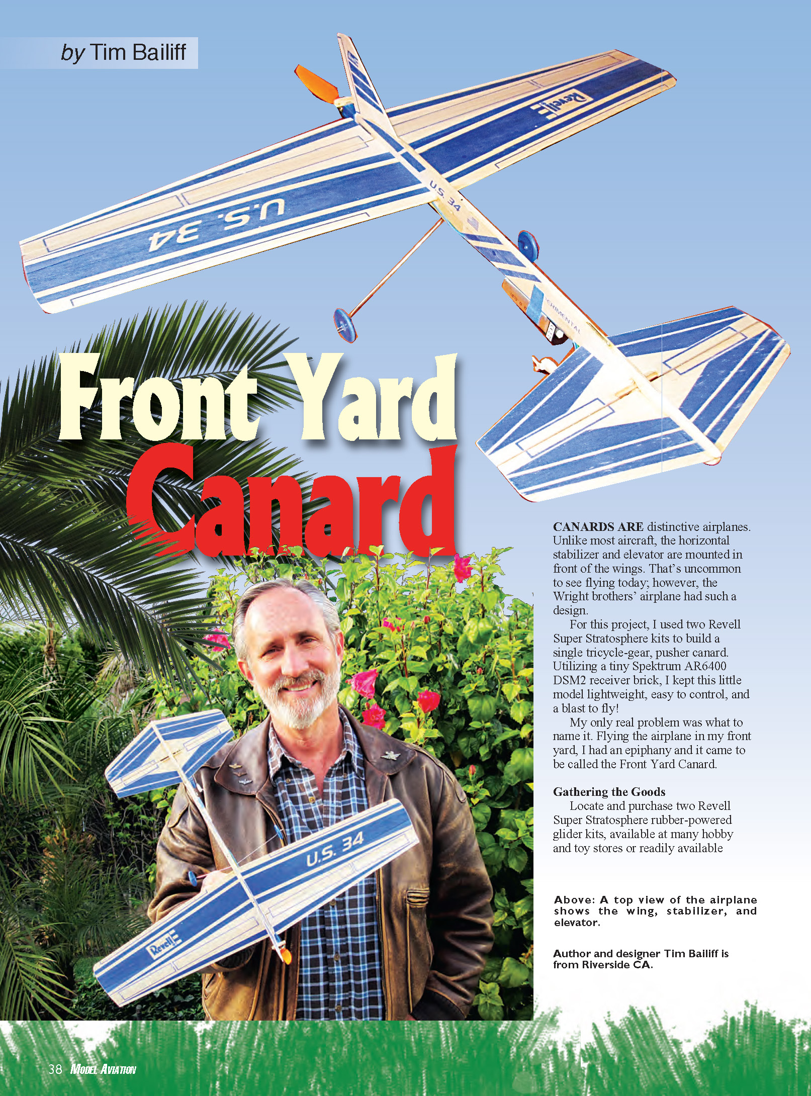
CANARDS ARE distinctive airplanes. Unlike most aircraft, the horizontal stabilizer and elevator are mounted in front of the wings. That's uncommon to see flying today; however, the Wright brothers' airplane had such a design.
For this project, I used two Revell Super Stratosphere kits to build a single tricycle-gear, pusher canard. Utilizing a tiny Spektrum AR6400 DSM2 receiver brick, I kept this little model lightweight, easy to control, and a blast to fly!
My only real problem was what to name it. Flying the airplane in my front yard, I had an epiphany and it came to be called the Front Yard Canard.
Gathering the Goods
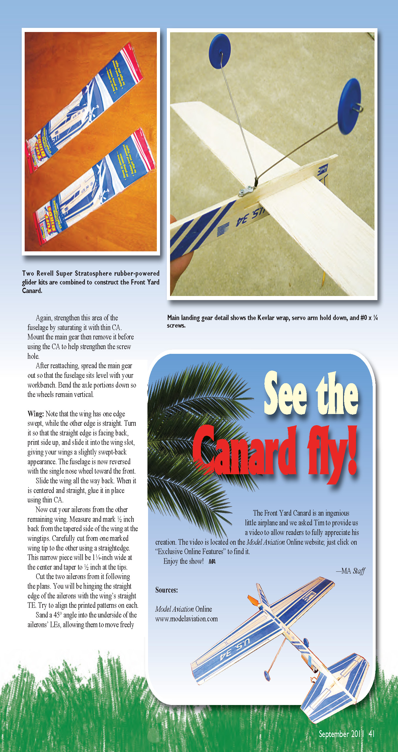
Locate and purchase two Revell Super Stratosphere rubber-powered glider kits, available at many hobby and toy stores or readily available online. Generally they are offered in red and blue, still packaged in their traditional plastic bags. Try to buy only those that have nice, firm balsa, without any noticeable warps, breaks, or cracks. One trick I use is to pick from the back of the rack where they are less likely to have been mishandled or possibly dropped. I buy more kits than needed to help increase my odds of getting sound pieces, and maybe have more parts for another project!
Once you're securely locked into your work lair, open the plastic packages and inspect them. If an essential piece is broken, use fast or thin CA to mend it. Use a light spray of kicker as well. From this point on, the printed instructions on the kits are useless. You are going to build a different airplane. Any reference to "the plan" will mean the "Front Yard Canard" plan.
Landing gear
- Choose the nicest fuselage from your kits. Cut off the wire rubber-band hook from the underside and carefully remove the remaining wire from the topside with a pair of pliers. From here on, the rear of the fuselage is the front.
- Nose gear:
- Take one of the kit's landing gear wires and, using the plan, straighten it and cut to length. Leave a single blue wheel attached.
- Push the wire up several inches through the bottom of the fuselage, using the same hole the rubber band hook occupied.
- Align the wheel with the fuselage then bend the wire protruding from the top as indicated on the plans so it resembles the top portion of the rubber band hook you removed.
- Pull the nose gear wire back down so the bent portion nests neatly into the top of the fuselage.
- Check alignment and when satisfied, soak both top and bottom with thin CA. Allow it to absorb into the balsa before using a light spray of kicker. Check the blue wheel itself and bend the axle portion of the wire as necessary to align vertically.
- Main gear:
- Use the entire remaining gear from your kits. Change the bend slightly by gently squeezing the wire together at the top, leaving a slight gap.
- Slightly beyond where the wire bends from horizontal to vertical, hold the wires together with six tight wraps of Kevlar or upholstery thread. Use a drop of CA to secure the thread.
- Locate the spot on the fuselage to which the main gear will attach as shown in the plans. The top faces forward and is located on the bottom ahead of the wing.
- To secure the gear in place, the author used a small piece of nylon cloth saturated with thin CA; a small nylon servo arm and two #0 x 1/4 screws can also be used. Again, strengthen this area of the fuselage by saturating it with thin CA. Mount the main gear then remove it before using the CA to help strengthen the screw hole.
- After reattaching, spread the main gear out so that the fuselage sits level with your workbench. Bend the axle portions down so the wheels remain vertical.
Wing
Note that the wing has one edge swept, while the other edge is straight. Turn it so that the straight edge is facing back, print side up, and slide it into the wing slot, giving your wings a slightly swept-back appearance. The fuselage is now reversed with the single nose wheel toward the front.
Slide the wing all the way back. When it is centered and straight, glue it in place using thin CA.
Now cut your ailerons from the remaining wing. Measure and mark 1/2 inch back from the tapered side of the wing at the wingtips. Carefully cut from one marked wingtip to the other using a straightedge. This narrow piece will be 1-1/4 inches wide at the center and taper to 1/2 inch at the tips.
Cut the two ailerons from it following the plans. You will be hinging the straight edge of the ailerons with the wing's straight TE. Try to align the printed patterns on each.
Sand a 45° angle into the underside of the ailerons' leading edges, allowing them to move freely and not bind. Cut two 9- x 1/2-inch strips of Blenderm tape to hinge them to the wing. Leave a 1/32-inch gap between the wing and aileron.
It's time to give your wing its airfoil shape. Begin by lightly dampening the top and bottom with water. Hold a slight undercamber bend in the wing as it dries. Refer to the plans airfoil template for the proper shape and bend location.
You may find it helpful to use a hair dryer to decrease the drying time, but don't overdo the heat. Make sure the LE and TE remain straight. Ensure each wing has the same shape and amount of airfoil.
Stabilizer and elevator
The distinctive feature about a canard is that the horizontal stabilizer and elevator are in the front. Use the stabilizer slot as provided in the front. Note that the slot is cut at an angle. The Front Yard Canard requires the stabilizer to have that same positive angle of attack.
Turn the stabilizer around so that the straight edge faces back so that the elevator will have a straight edge on which to hinge. Make sure the stabilizer is centered and straight and then glue it into place.
The elevator is constructed from the remaining stabilizer taken from the second Revell kit. Use the plans to cut the elevator to size and then in half. When cutting the two elevator halves to length, remove roughly 1/4 inch of balsa from the center. Ensure that the tips are flush so the printed patterns line up.
Temporarily tape the two elevator halves to the stabilizer. Make sure neither one touches the fuselage. You want roughly 1/16-inch clearance, so trim as necessary. Now remove them and set aside.
The two halves will be connected by using a 3/4-inch toothpick bridge. Cut a hole through the fuselage using a small hobby knife. Refer to the plans for the proper size, location, and shape. Temporarily tape the elevator halves back onto the stabilizer and position them carefully as if ready to hinge.
Cut the toothpick to length and pass it through the hole as shown in the plans. Trim enough balsa from the elevator leading edges to fit the toothpick into place and glue the toothpick in place with medium CA. Cut and place the 1/16-inch balsa doublers on the underside of the elevator halves. After gluing is complete, hinge your elevator using 1/2-inch strips of Blenderm tape leaving a 1/32-inch gap to allow the elevator to move easily.
Fin
When you mount the fin, leave enough room behind it for the motor mount to slide on. Place one of the blue plastic propeller units onto back of the airplane, sliding it all the way on. Cut a shallow slot for the fin on top of the fuselage, just ahead of the blue plastic propeller unit. Use the bottom of the fin to determine the length.
Remove enough balsa to allow for a snug fit, position correctly, remove the plastic unit, and glue the fin into place using thin CA.
Fuselage
Now you want to reinforce the front of the fuselage. The slit in the top of the fuselage is where the fin was originally designed to fit. Because you removed additional balsa, it has become a weak spot.
To reinforce this area, insert a 2-1/2-inch piece of .080-inch carbon-fiber rod lengthwise into this slot. Test-fit and trim as necessary then glue into place using thin CA. Allow the glue to slowly wick in under the rod, saturating the wood without letting it drip.
Motor mount
To modify the motor mount, use the same blue plastic propeller unit that you used during the fin placement. Cut the propeller shaft supports off flush to remove the propeller, leaving a small, hollow plastic box. The front of the unit angles down; you want that same downthrust for your motor.
Using a piece of 1/8-inch plywood, make a 3/8- x 1/4-inch crossbar at the top of the plastic unit. Refer to the plans and pictures for the proper shape.
Lightly sand the top of the plastic unit for better adhesion and squarely glue the crossbar in place. Tilt it slightly to keep the same downthrust and slide the entire unit onto the back of the fuselage and glue in place with thin CA.
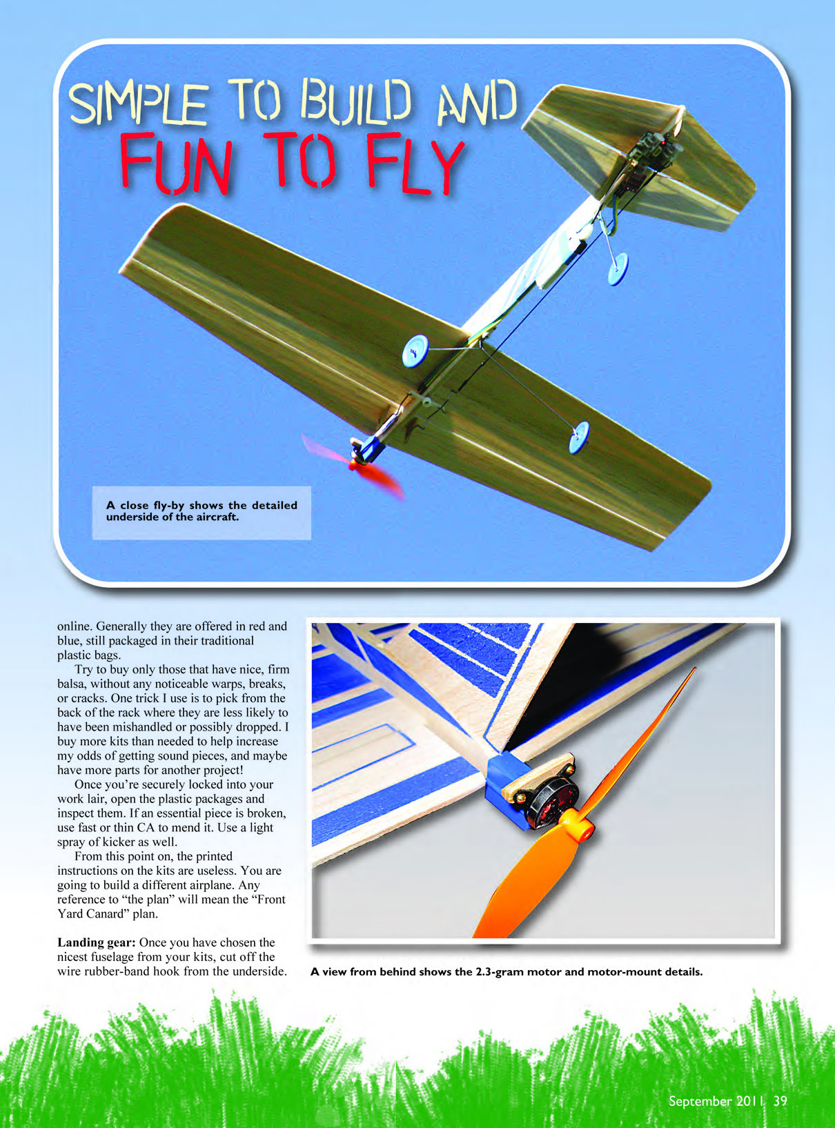
Micro motor
I chose an AP-02 7000kV 2.3-gram brushless micro motor from HobbyKing.com. It has a three-point mount built onto the motor housing. Use two mounting points for the top crossbar and the third in the center of the plastic unit. Mount the motor with three #0 x 1/4 screws. Drill small pilot holes to avoid possible splitting.
I used a GWS 3020 3 x 2 propeller. Turn it backward and press it directly onto the propeller shaft so that the writing on the propeller faces forward. Don’t bend the propeller shaft or damage the micro motor by pressing too hard. Use a needle-size drill to enlarge the hole in the propeller if necessary. It should fit snugly, but not extremely tight.
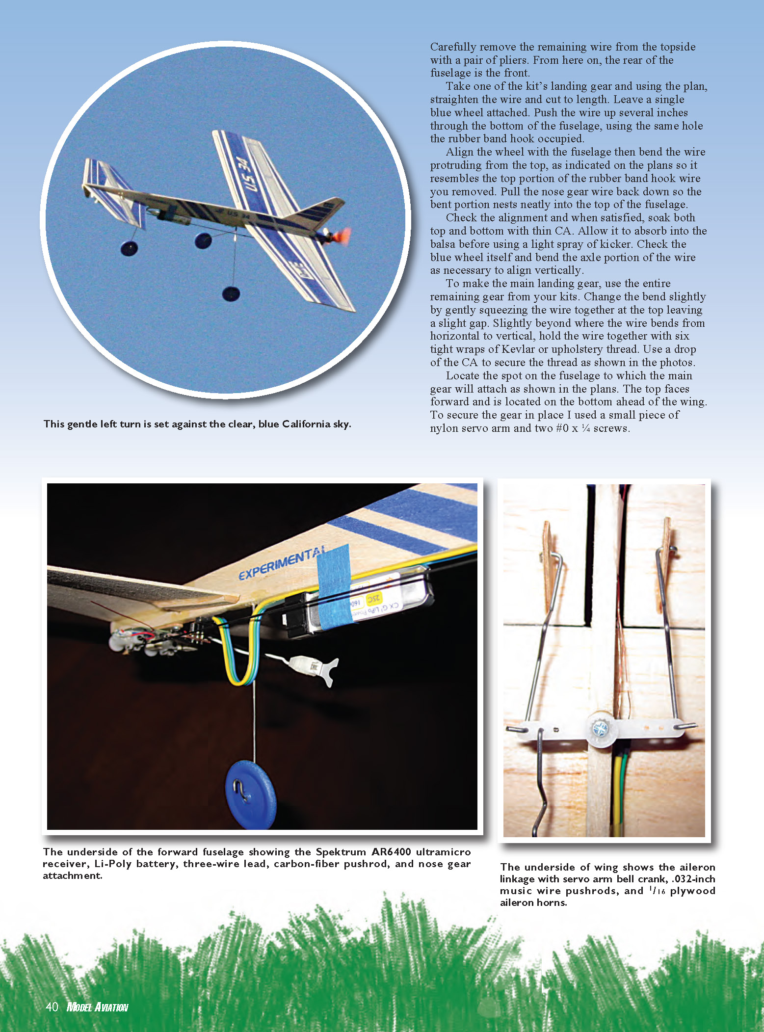
Electronics
The main electronic component is the Spektrum AR6400 DSM2. The AR6400 is a tiny receiver, two tiny linear servos (rudder and elevator), and a micro brushed speed control built onto one circuit board. I paired this “brick” with a DP-3A 1-gram, single-cell Li-Poly brushless speed controller.
I taped a Turnigy Nano-Tech 160 mAh, 1S Li-Poly single-cell battery to the fuselage behind the front landing gear with a strip of blue painter’s tape.
Mounting the AR6400
Make a servo mount from a 2- x 1/4-inch piece of 1/16-inch plywood and sand the ends round. Glue it to the back (flat), center of the AR6400 lengthwise. I used 5-minute epoxy because it gave me time to center and align the plywood mount. After the glue has dried, drill one 1/16-inch mounting hole in each protruding end.
Mount the brick to the bottom of the fuselage under the front stabilizer, slightly in front of the landing gear. Mount the plywood to the balsa fuselage with the AR6400 suspended underneath following the plans. Temporarily screw it into place with two #0 x 1/4 screws.
Remove it and coat the bottom of the fuselage at this location with thin CA. Allow some glue to seep into the screw holes, but keep them from sealing by piercing with a pin. Use a light spray of kicker to set the CA.
Replace the brick and screw it into place. It should feel solid and be parallel with the underside of the stabilizer.
The speed control
First, verify which end of the 1-gram DP-3A controller will plug into the brick. It will have three pins: one with a positive symbol, one with a negative symbol, and one with a signal. The pins will need to be bent slightly to fit into the three-position throttle jack at the end of the brick, facing backward. Plug in the controller accordingly using a small piece of Blenderm tape to secure it into the jack.
The controller comes with a separate three-pin plug. Solder a small-gauge, three-wire lead long enough to reach and likewise solder it onto the motor’s three wire lead.
Insulate all six solder joints with 3/64-inch heat-shrink tubing. Only apply heat to the tubing at the motor end of the lead for now, leaving the plug end simply in place. Plug the three-pin plug onto the three remaining pins protruding from the controller.
Beginning at the motor and working forward, secure the wire to the side of the fuselage with 1/4-inch strips of Blenderm, repositioning the wire to the bottom of the fuselage when you reach the LE. As you pass the nose gear, loop the wire down to take up any excess wire.
Control horns
You will need to cut two control horns for the ailerons and one for the elevator from 1/16-inch plywood. Check the plans for the correct shapes and locations.
Use medium CA to glue the elevator horn in place first. Note its placement with regard to the hinge line and the elevator servo on the brick.
Next glue the aileron control horns in place. Place them slightly behind and angling away from their hinge lines to produce a differential movement in the ailerons. You want each to move up more than the other moves down. This causes more drag on the up-aileron side and helps create a coordinated (rudderless) turn.
Cut a small piece of 3/16-inch plywood to guard the AR6400 brick. Sand it to shape and glue the guard to the bottom side of the airplane’s nose. This small protrusion will help protect the brick.
Pushrods
Make and install four pushrods and one bell crank and your Front Yard Canard will be finished! You are going to use a nylon servo arm as a bellcrank for your ailerons. Use the lightest two-arm, 1-inch servo arm you can find. Install it on the fuselage under the wing as shown in the plans.
Install it temporarily then remove and saturate the area with CA, using kicker to set the glue. Place a small washer down then install bellcrank socket side facing away from the fuselage bottom using a #0 x 1/4 screw. The head of the screw should fit into the center of the servo arm.
Following the plans, cut and bend two .032-inch piano wire pushrods to the indicated shape. At one end secure a short piece of .032-inch piano wire that has a Z bend in it. Bend a small V to help with final adjustments. Use eight wraps of Kevlar or upholstery thread for reinforcement and secure it all with a drop of thin CA.
Cut the carbon-fiber pushrod as indicated in the plans. At one end secure a short piece of .032-inch piano wire that has a Z bend in it. Bend a small V to help with final adjustments. Use eight wraps of Kevlar or upholstery thread for reinforcement and secure it all with a drop of thin CA.
When the pushrods are connected properly the ailerons should be even and in line with the wing. The bellcrank should be perpendicular with the fuselage.
On the other end of the elevator pushrod, attach a short piece of wire that fits the hole on the rudder servo arm on the brick. A thin pin bent into a Z and secured with thread works well. You can also use .032-inch music wire, but you will need to enlarge the hole on the brick's rudder servo arm slightly.
Use a thin pin or music wire for the elevator pushrod. The plans show the appropriate bend.
Attach the pushrods to the aileron bellcrank and elevator horn first. Temporarily unscrew the AR6400. After they are attached, you can easily screw the brick back down.
Setup
My Spektrum DX7 2.4 GHz transmitter is compatible with any DSM2 receiver. Mix the rudder function with the aileron function to make the servos move properly.
Now reprogram the function of the brushed motor jack on the AR6400, enabling the brushless motor controller to operate properly.
With the transmitter on, move the throttle level full forward and to the left corner. Hold the stick in that position and plug the battery into the AR6400. The receiver will blink three times indicating the setup change has been accepted. Release the stick and return it to the low throttle position.
Check the CG
While the battery is plugged in, place it at the location indicated on the plans using blue painter's tape to hold it in place. The CG is shown on the plan. Check your CG starting with the battery 1-1/4 inch ahead of the wing, on the fuselage. Move the battery slightly forward or aft to attain the right balance.
Checklist
- Hold the canard, slowly advancing the throttle to verify the engine is running properly. If you find it runs backward, resolder two of the three wires at the three-pin plug that is plugged onto the speed controller and shrink the remaining heat shrink tubing at that end.
- Check the elevator next. The canard's elevator works in reverse from that of a conventional airplane. It should move down when the stick is pushed back and move up when the stick is pushed forward. If this is not the case, correct it using your transmitter's reverse menu.
- Adjust the elevator throw's end points in your transmitter as well. It should move up and down approximately 1/2 inch. It can barely touch the aileron pushrod when in the full down (up-elevator) position.
- Finally check your ailerons. At the fuselage, these should move about 3/8 inch up and 1/4 inch down. This "differential" is already built in. The right aileron moves up and the left moves down when the stick is moved right and the opposite holds true. Use the transmitter to electronically reverse your ailerons if necessary.
Let's go fly
It's time to fly your Front Yard Canard. Expect some attention at the flying field. It's not every day that someone flies a canard. When your friends realize you're flying a converted rubber-band balsa glider, they will flip. Most of them played with these when they were kids, too.
I prefer to set up dual rates before I fly any airplane for the first time. I keep the high rate at 100% and set the lower rate at 60%. If it's too touchy, it can be fixed quickly with the flip of a switch.
When you are ready for takeoff, line your airplane up with the runway center line and smoothly advance the throttle to full. Although you have no rudder, when trimmed properly, it's no problem.
Your little Front Yard Canard will quickly accelerate in a straight line. With a touch of up-elevator, it's off the ground in roughly 8 to 10 feet with a nice brisk climbout.
Get the feel of your new airplane. Based on how you fly, the battery will give you between 5 and 10 minutes of flight time. Your Front Yard Canard will fly as well or better than most airplanes its size. Try some shallow S turns and a few Figure Eights.
After you have the feel, try some full-throttle maneuvers. I like to fly "three mistakes high."
- For rolls: begin in level flight. When ready, pull the nose up slightly and then lay the stick all the way over. You will be surprised at how nicely it will roll.
- For loops: again use full throttle. Let the nose drop to build a little speed, and then smoothly pull the stick all the way back. The canard will climb straight up and smoothly over the top. I usually cut the throttle on the back side just to be safe.
Landing
Landing is a breeze: line up with the runway and ease back on the throttle. Because it's so light, a touch of power will keep you moving nicely. Keep the nose pointed down slightly as you make your final approach, and fly it all the way in. Although distinctly different, it feels light and responsive all the way down. Just before you touch down, pull the throttle off and gently add up-elevator.
Debriefing
Driveways make excellent runways, too! If you have room, try flying the canard in your own front yard. Using partial throttle, this spirited little park flyer is capable of handling light wind. With full throttle, it is aerobatic and can loop, roll, and perform all the maneuvers that a conventional aileron/elevator airplane can. Try it inside as well. The Front Yard Canard is agile enough to maneuver easily in a gym or some indoor venue using half throttle. You will have loads of fun performing Figure Eights and executing perfect touch-and-goes.
With all the fun you'll soon be having, don't hesitate to buzz the tower!
Transcribed from original scans by AI. Minor OCR errors may remain.

