
Fundamentals of Stability
by Dave Harding
“YOU SHOULD USE a ‘flat-bottomed’ airfoil on a trainer because it is more stable.”
How many times have you read that often-quoted statement? As is so much folklore, it is untrue. I will explain why and what does make a stable model (or full-scale) airplane.
What we mean by “stable”
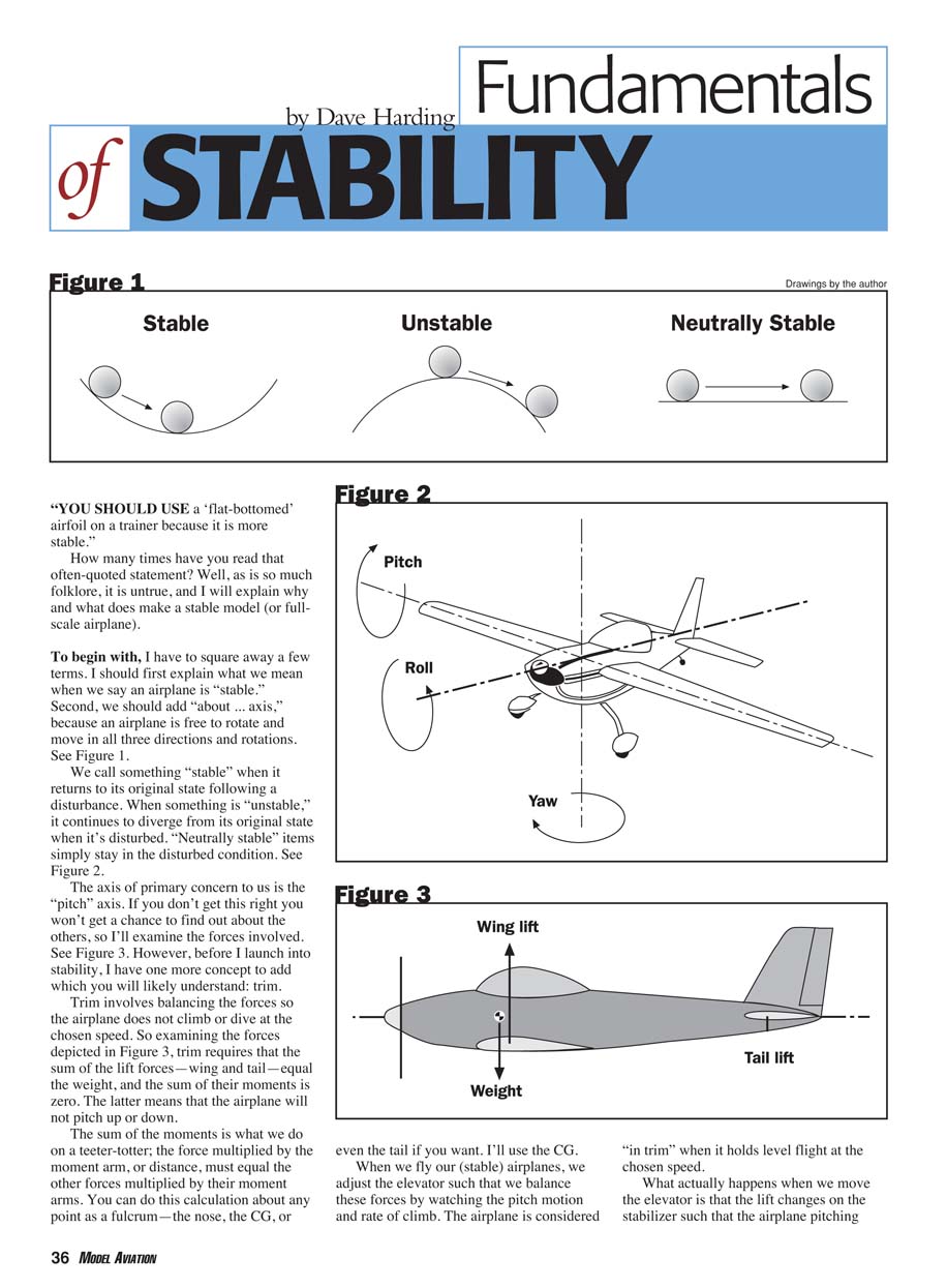
We call something “stable” when it returns to its original state following a disturbance. When something is “unstable,” it continues to diverge from its original state after a disturbance. “Neutrally stable” items simply stay in the disturbed condition.
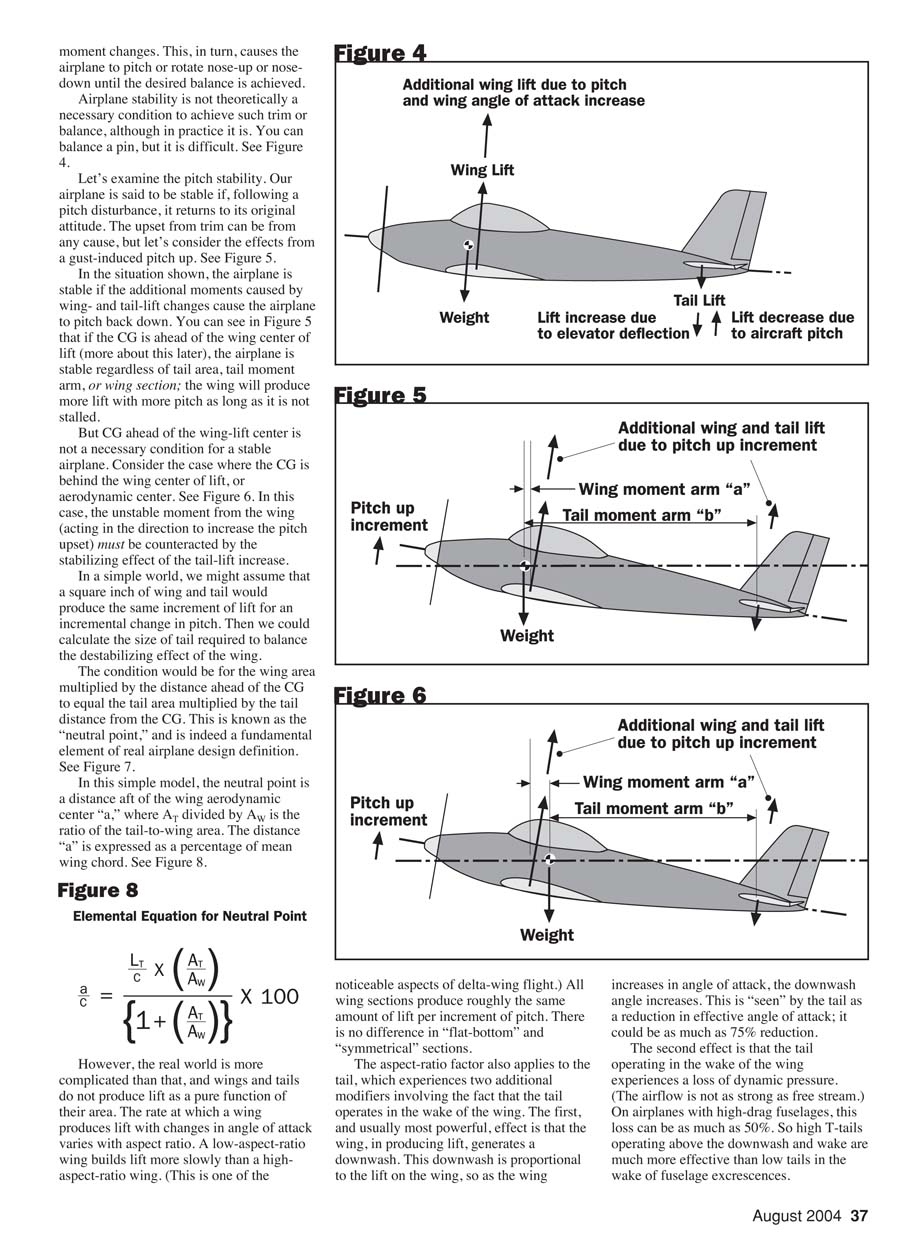
We should add “about ... axis,” because an airplane is free to rotate and move in all three directions and rotations. The axis of primary concern to us is the pitch axis. If you don’t get pitch stability right you won’t get a chance to find out about the others, so I’ll examine the forces involved (see Figures 1–3 in the original).
Trim
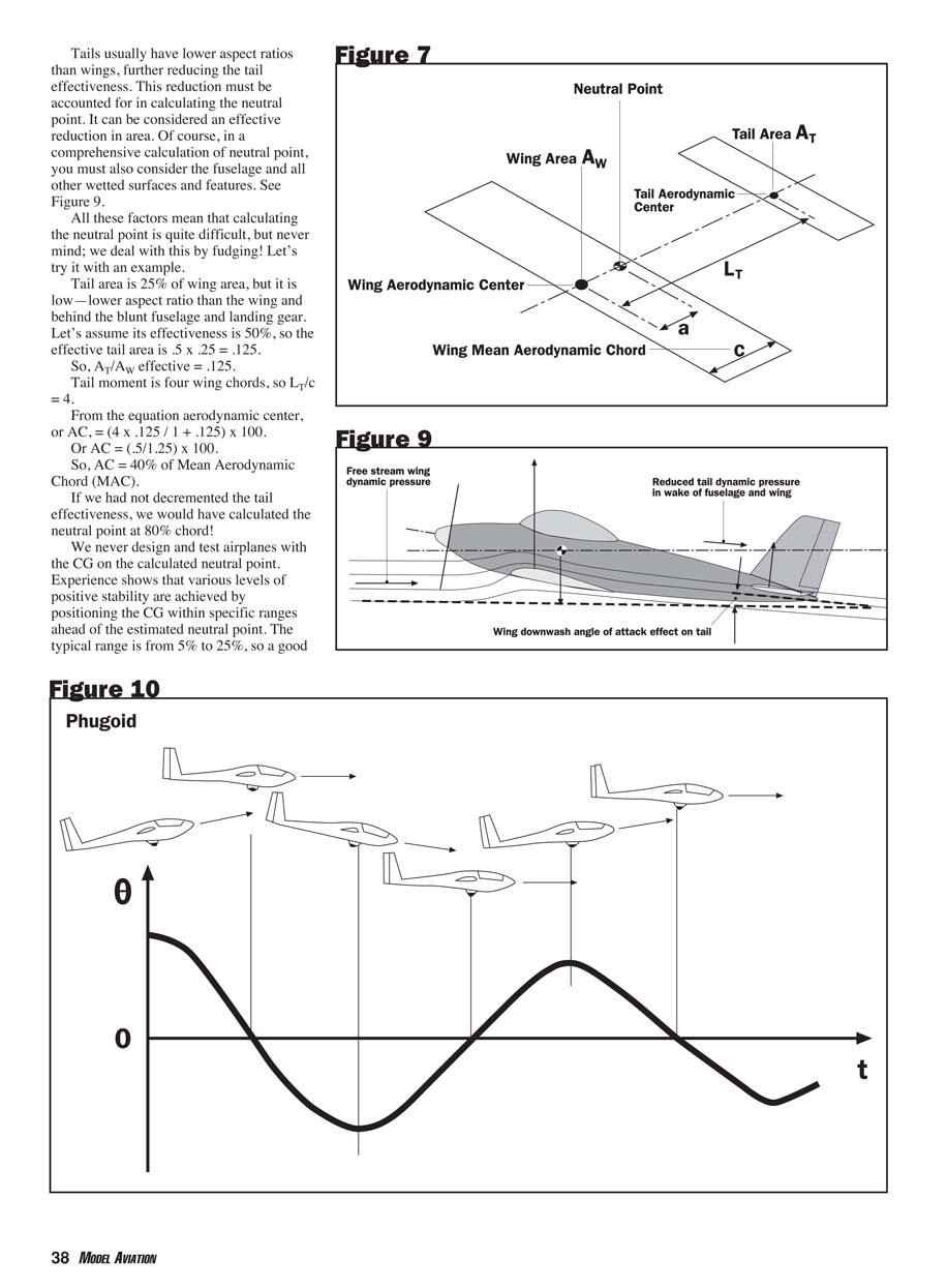
Trim involves balancing the forces so the airplane does not climb or dive at the chosen speed. Examining the forces, trim requires that the sum of the lift forces—wing and tail—equal the weight, and that the sum of their moments is zero. The latter means that the airplane will not pitch up or down.
The sum of the moments is what we do on a teeter-totter: force multiplied by the moment arm (distance) must equal the other forces multiplied by their moment arms. You can do this calculation about any point as a fulcrum—the nose, the CG, or even the tail. I’ll use the CG.
When we fly our (stable) airplanes, we adjust the elevator such that we balance these forces by watching pitch motion and rate of climb. The airplane is “in trim” when it holds level flight at the chosen speed.
When we move the elevator the lift on the stabilizer changes, so the airplane pitching moment changes. This causes the airplane to pitch nose-up or nose-down until the desired balance is achieved.
Airplane stability is not, in theory, a necessary condition to achieve trim or balance—although in practice it is. You can balance a pin, but it is difficult.
Pitch stability
An airplane is said to be stable in pitch if, following a pitch disturbance, it returns to its original attitude. Consider a gust-induced pitch-up. The airplane is stable if the additional moments caused by wing- and tail-lift changes cause the airplane to pitch back down.
If the CG is ahead of the wing center of lift (the aerodynamic center), the wing will produce more lift with more pitch as long as it is not stalled, and the airplane will be stable regardless of tail area, tail moment arm, or wing section. However, CG ahead of the wing-lift center is not a necessary condition for stability.
If the CG is behind the wing aerodynamic center, the unstable moment from the wing (which tends to increase the pitch upset) must be counteracted by the stabilizing effect of the tail-lift change.
Neutral point
In a simple model, assume a square inch of wing and tail produce the same incremental lift for an incremental change in pitch. Then the wing area multiplied by the distance ahead of the CG must equal the tail area multiplied by the tail distance from the CG. This condition defines the neutral point—a fundamental element of airplane design.
Expressed as a distance aft of the wing aerodynamic center, the neutral point (a) as a percentage of mean wing chord (c) can be written:
a / c = [(LT / c) × (AT / AW)] / [1 + (AT / AW)] × 100
where:
- LT = tail moment arm (distance from CG to tail) expressed in wing chord units (LT/c)
- AT = tail area
- AW = wing area
Real-world complications and tail effectiveness
The real world is more complicated. Wings and tails do not produce lift strictly as a function of their area. The rate at which a surface produces lift with changes in angle of attack varies with aspect ratio: a low-aspect-ratio wing builds lift more slowly than a high-aspect-ratio wing. All wing sections operating in the Reynolds number region typical of RC models produce their aerodynamic forces at a relatively fixed location (about the quarter-chord), so there is little difference in longitudinal stability between “flat-bottom” and “symmetrical” sections in that respect.
The tail’s effectiveness is modified further because the tail operates in the wing’s wake:
- Downwash: The wing, in producing lift, generates a downwash. As angle of attack increases, downwash angle increases. The tail “sees” a reduced effective angle of attack — it could be reduced by as much as 75% in some cases.
- Loss of dynamic pressure: The tail in the wing’s wake (and behind a blunt fuselage or landing gear) experiences reduced dynamic pressure. On airplanes with high-drag fuselages, this loss can be as much as 50%.
Tails usually have lower aspect ratios than wings, further reducing tail effectiveness. This reduction can be accounted for as an effective reduction in tail area. In comprehensive neutral-point calculations, you must also consider the fuselage and other wetted surfaces and features.
Because of these effects, calculating the neutral point accurately is difficult in practice.
Worked example (with corrected math)
Suppose:
- Tail area is 25% of wing area: AT / AW = 0.25
- Tail is low and behind a blunt fuselage so its effectiveness is only 50% → effective AT / AW = 0.5 × 0.25 = 0.125
- Tail moment arm is four wing chords → LT / c = 4
Apply the neutral-point formula:
a / c = [(4) × (0.125)] / [1 + 0.125] × 100 = 0.5 / 1.125 × 100 ≈ 44.4% of Mean Aerodynamic Chord (MAC)
If we had not decremented the tail effectiveness (i.e., AT / AW = 0.25), the neutral point would be:
a / c = (4 × 0.25) / (1 + 0.25) × 100 = 1 / 1.25 × 100 = 80% MAC.
So accounting for reduced tail effectiveness moves the neutral point substantially forward in this example.
We never design and test airplanes with the CG on the neutral point. Experience shows that positive stability is achieved by positioning the CG within specific ranges ahead of the estimated neutral point—typically 5% to 25% of MAC. A good starting point might be 15% ahead of the neutral point. Applying that to the example above would give a CG around 44.4% − 15% = ~29% chord (so starting around 25% chord is reasonable).
How much stability?
What level of stability you provide depends on application. Stability and control must be in harmony: high stability makes an airplane more difficult to control.
Longitudinal stability couples pitch attitude, lift, flight path, and speed. An upset in pitch causes a stable airplane to climb and lose speed, then pitch down and gain speed until it pitches up again. This oscillation is called the phugoid. The phugoid can be quite pronounced in highly stable airplanes, although it usually damps out with good design.
High longitudinal stability also causes strong coupling between speed and pitch trim. With higher stability there is a larger offset between the equilibrium angle of attack and the trimmed angle of attack; therefore speed changes require larger elevator deflections. The balance of moments is between the CG (where the airplane weight acts) and the neutral point (where the aerodynamic forces act). As speed increases, aerodynamic forces increase while weight does not, requiring larger aerodynamic trim changes to rebalance.
For straight flight with large speed variation, you must input large pitch-trim control inputs coordinated with speed. This is undesirable in an aerobatic airplane where you want it to point and stay pointed without further input, but it is no problem for a trainer where you want the aircraft to overcome inadvertent upsets by a novice pilot.
Sailplanes and minimizing trim drag
Sailplanes are designed for lowest drag and high aerodynamic efficiency. Greater stability often involves the tail producing a downforce to counteract wing lift, forcing the wing to produce more lift and therefore more drag—this is trim drag.
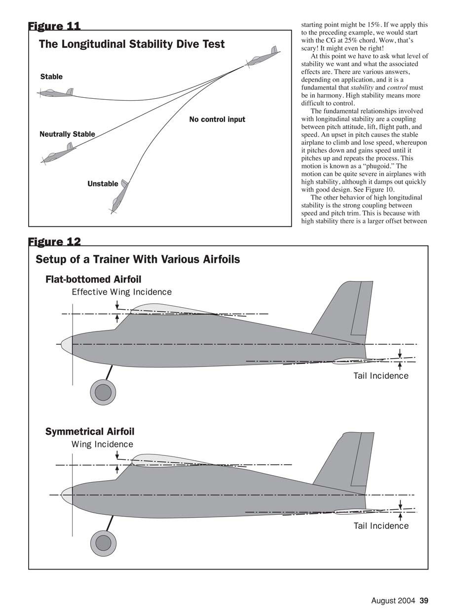
High-performance sailplanes minimize trim drag by using small tails and aft CG locations to achieve the minimum stability necessary for controlled flight. A practical trimming technique used by some is the “dive test”: take the glider to altitude, put it in a dive, and then let go of the stick. If the glider pulls out strongly, the CG is too far forward (or the airplane too stable)—move the CG aft and repeat. At some point the glider will pitch down and steepen the dive without recovery; if you can save it, you have controlled an unstable airplane.
As an example of practical CG manipulation, the Lockheed L-1011 airliner was retrofitted with a fuel tank in the horizontal tail. It is empty on takeoff and landing for increased stability, and fuel is pumped into it in cruise to move the CG aft and reduce trim drag, reducing fuel consumption. Fuel is pumped forward again for low-altitude flight in turbulence and for landing.
Design practice
In practice, the stability margin—the distance between the CG and the neutral point—is typically 5% to 25% of MAC. Trainers and sport/scale airplanes favor the forward end of that range; aerobatic airplanes and gliders favor the aft end. Calculating the MAC and AC of complex wing shapes can be tricky, so start conservatively and use flight testing (such as the dive test) to refine CG location.
Note that specific wing airfoils have little effect on longitudinal stability. Most airfoils in the Reynolds-number region of RC models produce their aerodynamic forces near the quarter-chord, so the aerodynamic center remains relatively fixed over the pitch range of interest. Some cambered airfoils (flat-bottomed or semi-symmetrical) do have a small change in the aerodynamic center with angle of attack, which can be slightly destabilizing (a small pitch-up with increased angle of attack).
Symmetrical NACA airfoils have practically no pitching moment with angle of attack. This was a primary reason why early helicopters used symmetrical sections (e.g., NACA 0012) before hydraulically boosted controls and the aerodynamic advantages of cambered airfoils made cambered blades more practical.
Flat-Bottomed Airfoils for Trainers?
So why is it said that you must use a “flat-bottomed” airfoil on a trainer?
Although flat-bottomed airfoils are no more stable than symmetrical airfoils, they do have higher lift capability at a given angle of attack. That allows lower takeoff and landing speeds or more margin to accommodate inadvertent control inputs or recovery from poor flight-path control.
Another practical factor is initial trim setup. Extremely stable airplanes may require the horizontal tail to produce downward lift while the wing lifts upward. To satisfy this condition the decalage—the difference between wing and tail incidence—has to be large. For example, the wing may need +4° and the tail 0° to −3°.
If you build a conventional trainer fuselage with a flat top and bottom and then use a flat-bottomed airfoil (such as the Clark Y) and a low, slab tail, you automatically have about 4° of decalage because the zero-lift line on the flat-bottomed airfoil is roughly at +4°. That makes initial setup simpler.
By contrast, if you want to use a symmetrical airfoil you must shape the upper fuselage or otherwise mount the wing to achieve the necessary real incidence to get the same decalage—more complicated in construction.
Could it really be this simple? Tell me if you know the right answer—please!
MA
Dave Harding 4948 Jefferson Dr. Brookhaven, PA 19015
Transcribed from original scans by AI. Minor OCR errors may remain.

