
Go fast and turn left—or right and up and down if you want
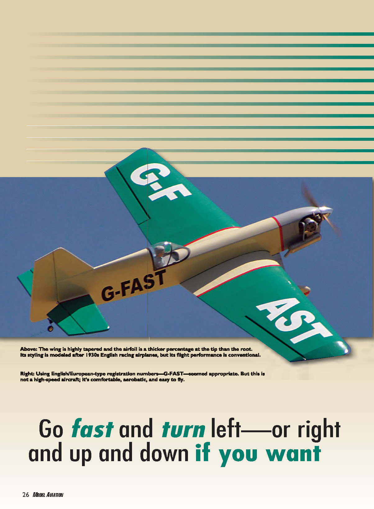
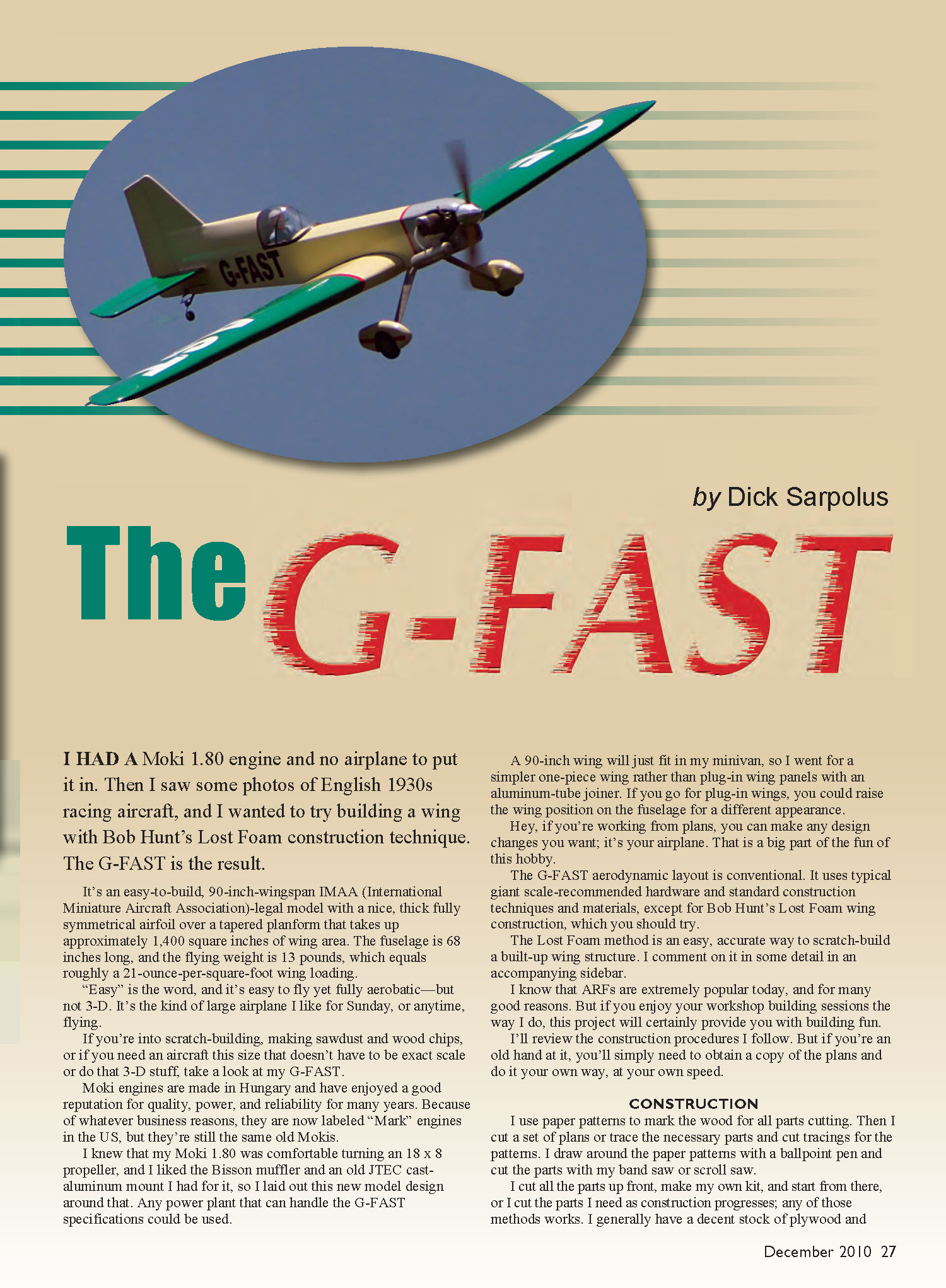
I had a Moki 1.80 engine and no airplane to put it in. Then I saw some photos of English 1930s racing aircraft, and I wanted to try building a wing with Bob Hunt’s Lost Foam construction technique. The G-FAST is the result.
It’s an easy-to-build, 90-inch-wingspan IMAA (International Miniature Aircraft Association)-legal model with a thick, fully symmetrical airfoil over a tapered planform that takes up approximately 1,450 square inches of wing area. The fuselage is about 67–68 inches long, and the flying weight is 13 pounds, which equals roughly a 21-ounce-per-square-foot wing loading.
“Easy” is the word: it’s easy to build and easy to fly, yet fully aerobatic—just not 3-D. It’s the kind of large airplane I like for Sunday, or anytime, flying. If you enjoy scratch-building, making sawdust and wood chips, or you need an aircraft this size that doesn’t have to be exact scale or do 3-D, take a look at the G-FAST.
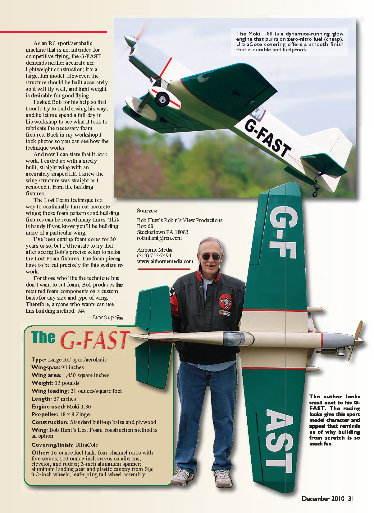
Moki engines are made in Hungary and have long had a reputation for quality, power, and reliability. In the U.S. they are sometimes labeled “Mark” engines, but they are the same Mokis. I knew my Moki 1.80 was comfortable turning an 18 x 8 propeller, and I liked the Bisson muffler and an old JTEC cast-aluminum mount I had, so I laid out this design around that installation. Any powerplant that fits the G-FAST specifications could be used.
A 90-inch wing will just fit in my minivan, so I went for a simpler one-piece wing rather than plug-in panels with an aluminum-tube joiner. If you prefer plug-in wings, you can raise the wing position on the fuselage for a different appearance. If you’re working from plans, make any design changes you want—it’s your airplane, and that’s part of the fun.
The aerodynamic layout is conventional. It uses typical giant-scale–recommended hardware and standard construction techniques and materials, except for Bob Hunt’s Lost Foam wing construction, which you should try. I’ll review the construction procedures I follow; if you’re experienced, obtain a copy of the plans and build at your own speed.
Construction
I use paper patterns to mark the wood for all parts. I cut a set of plans or trace the necessary parts and cut tracings for patterns. I draw around the paper patterns with a ballpoint pen and cut the parts with my band saw or scroll saw.
I either cut all the parts up front to make my own kit, or I cut parts as construction progresses—either method works. I generally keep a decent stock of plywood and balsa on hand, so I examine the plans and order more wood than I think I’ll need. The wood probably won’t go to waste; you’ll need it for repairs and for constructing your next project.
I’ve had good luck with wood from several mail-order suppliers, and I’m glad to see Lone Star Balsa back in business furnishing balsa, plywood, and basswood.
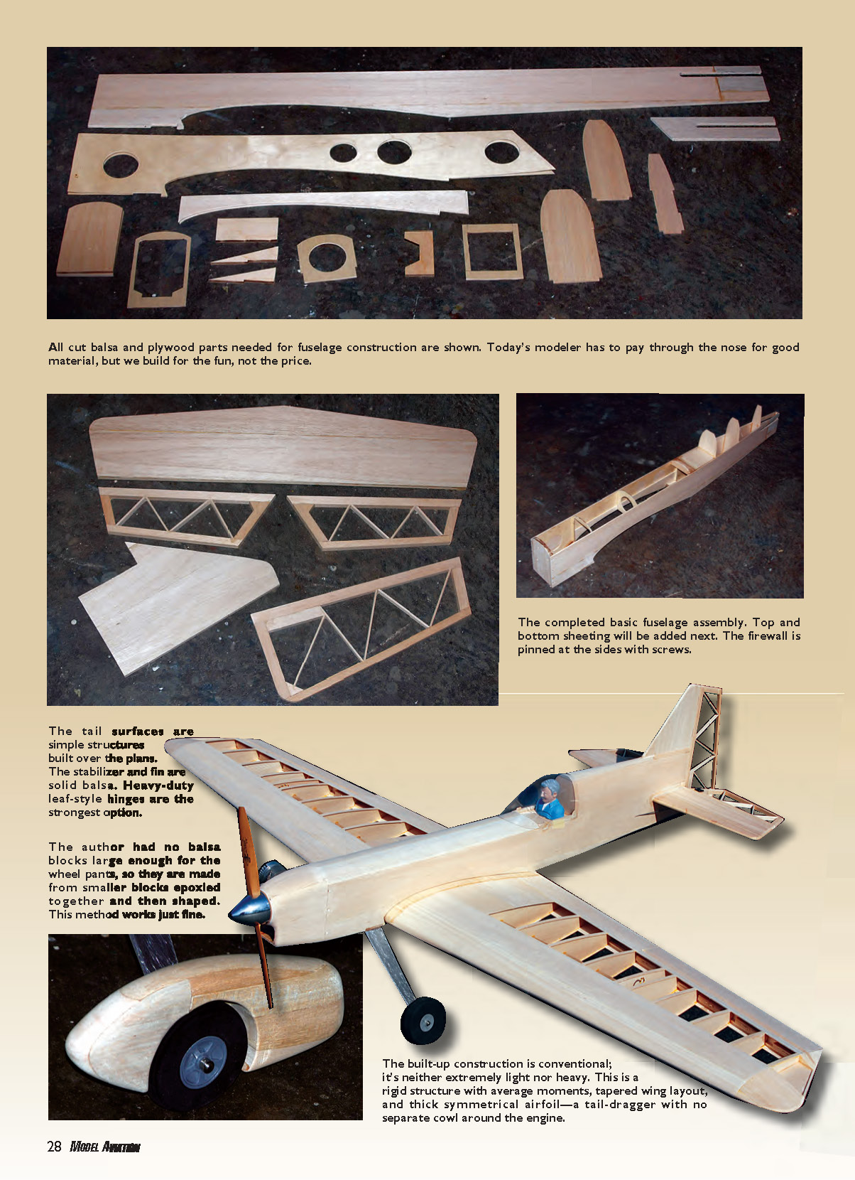
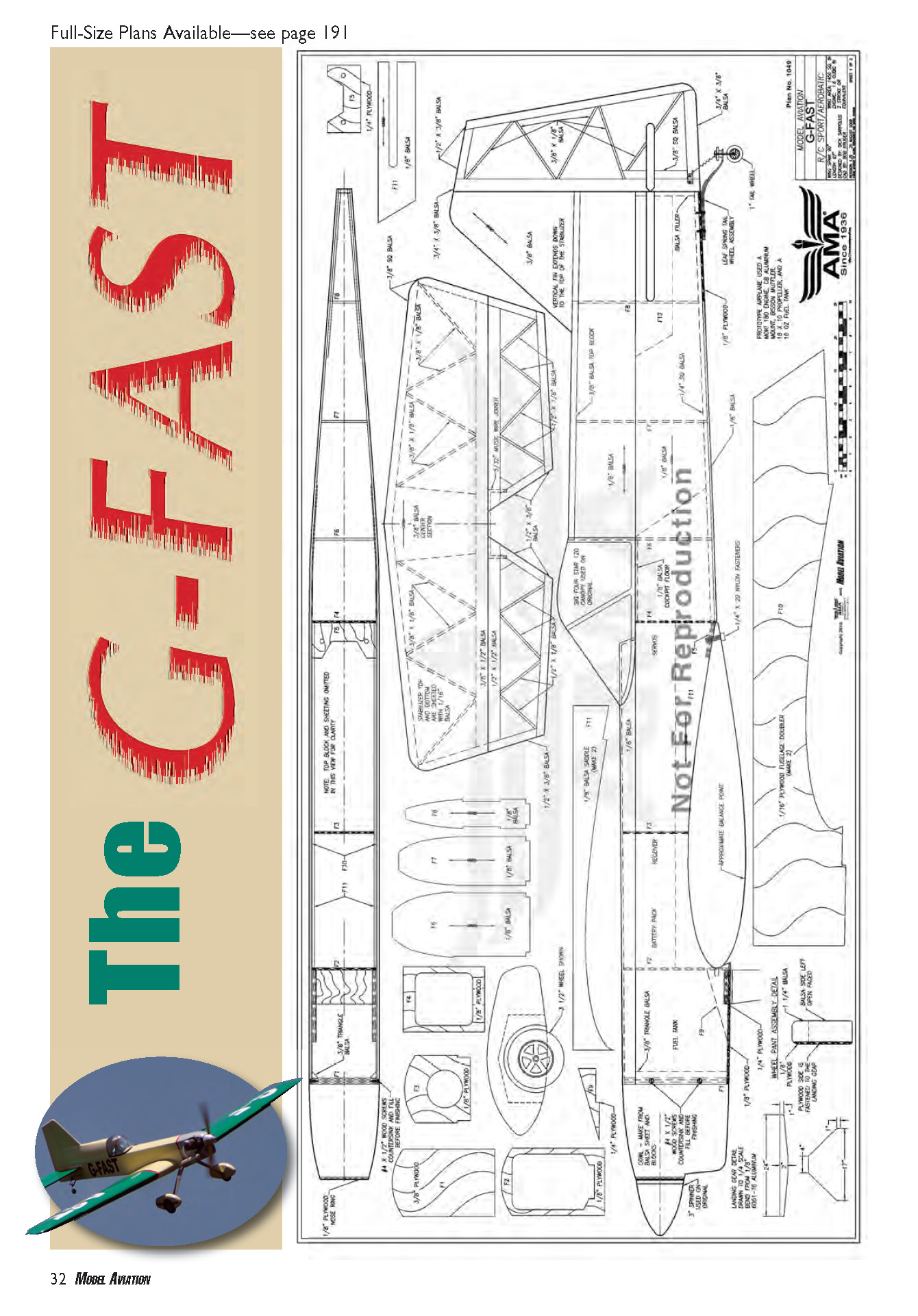
All cut balsa and plywood parts needed for fuselage construction are shown on the plans. The completed basic fuselage assembly gets top and bottom sheeting next; the firewall is pinned at the sides with screws. The tail surfaces are simple: the stabilizer and fin are solid balsa, and heavy-duty leaf-style hinges are the strongest option. If you don't have large balsa blocks for the wheel pants, smaller blocks epoxied together and shaped work fine.
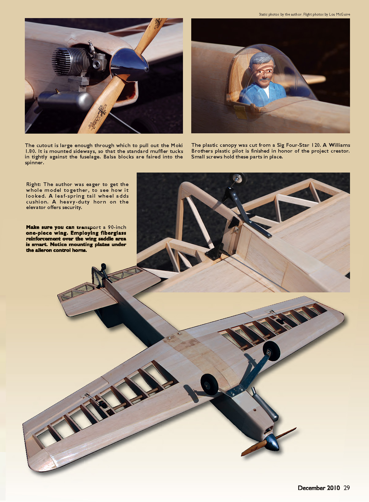
For this model the built-up construction is conventional—neither extremely light nor heavy. It’s a rigid structure with average moments, a tapered wing layout, and a thick symmetrical airfoil. The G-FAST is a taildragger with no separate cowl around the engine. The engine cutout is large enough to pull out the Moki 1.80; I mounted it sideways so the muffler tucks tightly against the fuselage, and I faired balsa blocks into the spinner.
The plastic canopy was cut from a Sig Four-Star 120 and a Williams Brothers plastic pilot was finished for the model. Small screws hold these parts in place. I used a leaf-spring tailwheel for cushion, and a heavy-duty horn on the elevator for security. Make sure you can transport a 90-inch one-piece wing. Fiberglass reinforcement over the wing saddle area is smart. Note the mounting plates under the aileron control horns.
Lost Foam Building System
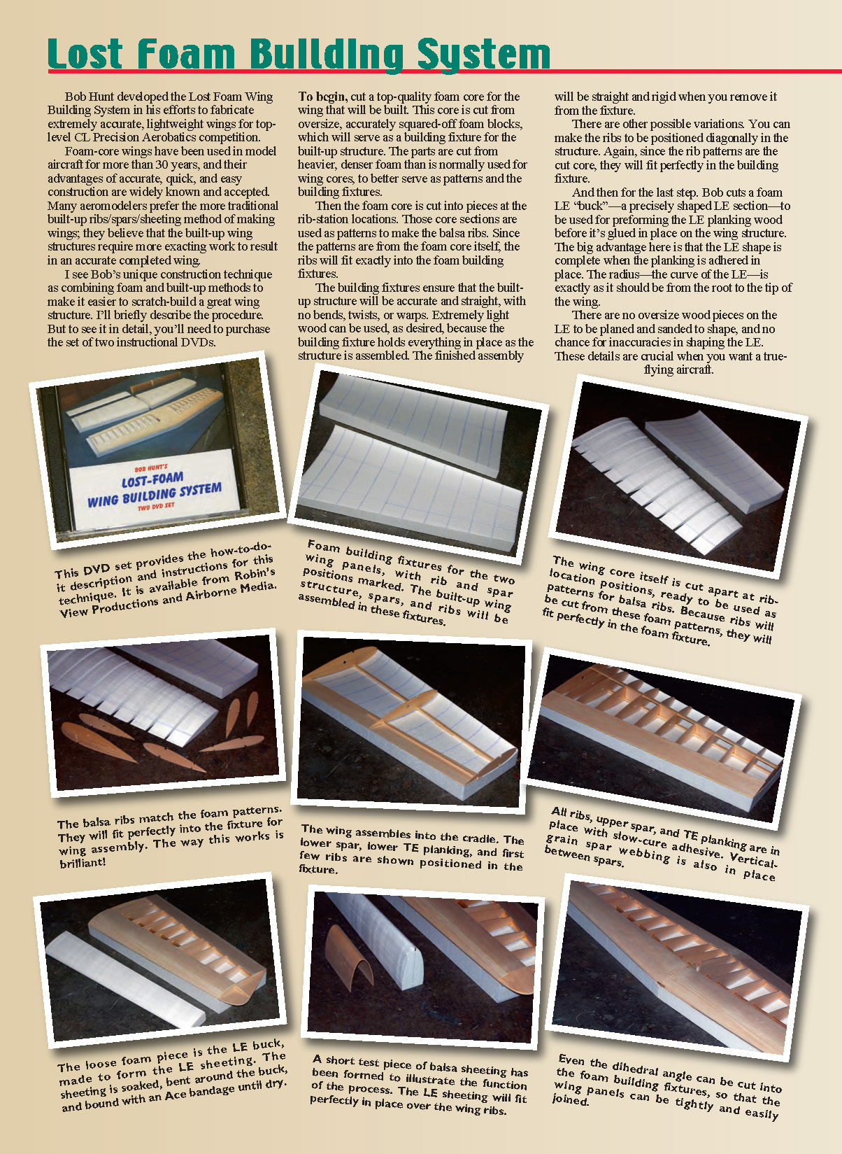
Bob Hunt developed the Lost Foam Wing Building System to fabricate extremely accurate, lightweight wings for top-level CL Precision Aerobatics competition. Foam-core wings have been used in model aircraft for more than 30 years; their advantages of accurate, quick, and easy construction are well known. Many modelers still prefer traditional built-up ribs/spars/sheeting, believing those methods yield very accurate wings, but Bob’s method combines foam and built-up approaches to make scratch-building an accurate wing easier.
Brief overview of the procedure:
- Cut a top-quality foam core for the wing from oversize, accurately squared foam blocks. Use heavier, denser foam than normally used for cores so the core will serve as a precise building fixture and pattern.
- Cut the foam core into pieces at the rib-station locations. Use those core sections as patterns to make the balsa ribs; since the patterns come from the foam core itself, the ribs fit exactly into the foam fixtures.
- Assemble the built-up structure on the foam fixtures. The fixtures hold everything straight and true, allowing use of very light wood without introducing twists or warps.
- Cut a foam leading-edge (LE) “buck” to preform the LE planking before gluing. The LE radius is complete when the planking is adhered, with no oversized wood to plane and sand and no chance for inaccuracies in shaping the LE from root to tip.
The Lost Foam fixtures can be reused many times, which is handy if you plan to build more of the same wing. Bob produces required foam components on a custom basis if you don’t want to cut foam yourself. I spent a day in Bob’s workshop and then built a nicely straight wing with an accurately shaped LE—this technique does work well.
—Dick Sarpolus
Wing
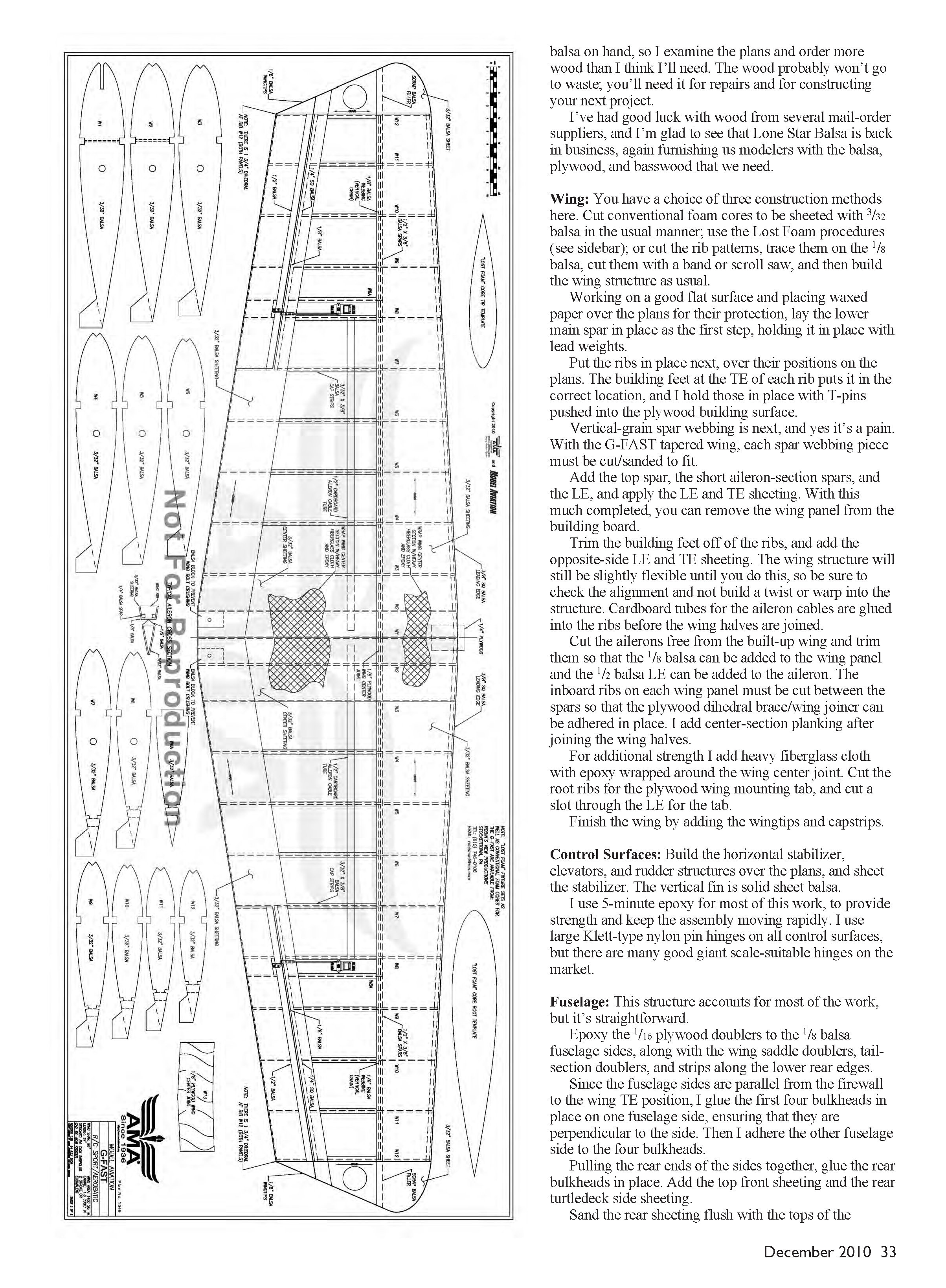
You have three construction choices:
- Cut conventional foam cores and sheet them with 3/32" balsa in the usual manner.
- Use the Lost Foam procedures described above.
- Cut the rib patterns, trace them on 1/8" balsa, cut the ribs with a band or scroll saw, and build the wing as a traditional built-up structure.
Build tips:
- Work on a good flat surface and place waxed paper over the plans. Lay the lower main spar in place first, holding it with lead weights.
- Put the ribs in place over their positions on the plans. The building feet at the trailing edge (TE) of each rib position them correctly; hold them with T-pins into the plywood building surface.
- Add vertical-grain spar webbing (each piece must be cut/sanded to fit on the tapered wing), then add the top spar, short aileron-section spars, the LE, and apply the LE and TE sheeting. At this point you can remove the wing panel from the building board.
- Trim the building feet off the ribs and add the opposite-side LE and TE sheeting. The structure will be slightly flexible until both sides are completed—check alignment closely and avoid building in a twist.
- Glue cardboard tubes for the aileron cables into the ribs before joining wing halves.
- Cut the ailerons free, trim them, add 1/8" balsa to the wing panel and a 1/2" balsa LE to the ailerons. Cut the inboard ribs between the spars to accept the plywood dihedral brace/wing joiner and add center-section planking after joining halves.
- Reinforce the wing center joint with heavy fiberglass cloth and epoxy wrapped around the joint.
- Cut root ribs for the plywood wing mounting tab and cut a slot through the LE for the tab. Finish with wingtips and cap strips.
Control Surfaces
- Build the horizontal stabilizer, elevators, and rudder over the plans and sheet the stabilizer. The vertical fin is solid sheet balsa.
- Use 5-minute epoxy for much of this work to provide strength and speed the build.
- I use large Klett-type nylon pin hinges on all control surfaces, but many giant-scale–suitable hinges are available.
Fuselage
This structure takes most of the work but is straightforward.
- Epoxy 1/16" plywood doublers to the 1/8" balsa fuselage sides, including wing saddle doublers, tail-section doublers, and strips along the lower rear edges.
- Since the fuselage sides are parallel from the firewall to the wing TE position, glue the first four bulkheads to one side, ensuring they are perpendicular, then adhere the other side to those bulkheads.
- Pull the rear ends of the sides together and glue the rear bulkheads in place. Add top-front sheeting and the rear turtledeck side sheeting.
- Sand the rear sheeting flush with the bulkheads, add the thicker top piece and plane/sand to shape. Do not add the bottom rear sheeting until the tail surfaces and pushrod linkages are in place.
- Use a 3/8" plywood firewall for large engines, typically epoxying together 1/8" and 1/4" plywood. Drill two screws on each side through the plywood fuselage doublers into the firewall sides for extra security.
- Add the plywood wing mount plate and landing gear mount plate; back these with additional 1/4" plywood for more depth for the 1/4-20 tapped holes for the nylon bolts. Add plywood at the end of the fuselage for the tailwheel mount.
- With the wing bolted in place, add the horizontal stabilizer and line it up with the wing, then add the vertical fin and align it with the horizontal stabilizer and wing. Work through the open bottom of the fuselage and cut holes in bulkheads to clear elevator and rudder pushrods.
- I prefer carbon-fiber pushrods with 4-40 hardware. Recess a 1/4" plywood mounting plate in each control surface for the control horn and epoxy it in place before adding bottom fuselage planking.
- I made wheel pants from plywood and balsa, leaving the outside open around the wheel for an old-time appearance.
- I mounted the Moki 1.80 sideways and glued balsa blocks around it to fair into the spinner with a simulated air inlet below the spinner. A round fiberglass cowl could be used for a radial look.
Rather than fabricate 6061-T6 aluminum landing gear, I used a Sig Four-Star 120 landing gear and canopy, trimmed to fit. A metal leaf-spring tailwheel assembly was used, coupled with small springs to the rudder for steering. A 16-ounce fuel tank works well; use a 20-ounce tank for longer flights.
Finishing
I used UltraCote to cover the model in a trim scheme resembling 1930s racing aircraft. Computer-cut vinyl registration numbers in English/European style gave it a foreign flavor. “G-FAST” seemed an appropriate registration and provided the project name. A 3" aluminum spinner, 3 1/2" wheels, and other standard hardware were used.
Flying
Despite the styling, this is not a racer; the thick wing keeps the flying speed moderate while enabling full aerobatic capability. However, the powerful Moki makes it quite fast at full throttle. I run an 18 x 8 Zinger propeller on FAI (no-nitro) fuel; the engine is designed for no-nitro fuel with high compression, which also keeps fuel costs down.
Before test flights I adjusted control throws to suit my habits and ended up with a comfortable, fun-flying machine. This project is a lot of fun to build and fly.
The G-FAST (specifications)
- Type: Large RC sport/aerobatic
- Wingspan: 90 inches
- Wing area: 1,450 square inches
- Weight: 13 pounds
- Wing loading: 21 ounces/square foot
- Length: 67 inches
- Engine used: Moki 1.80
- Propeller: 18 x 8 Zinger
- Construction: Standard built-up balsa and plywood
- Wing: Bob Hunt's Lost Foam construction method is an option
- Covering/finish: UltraCote
- Other: 16-ounce fuel tank (20-oz optional); four-channel radio with five servos; 100 oz-in servos on ailerons, elevator, and rudder; 3" aluminum spinner; aluminum landing gear and plastic canopy from Sig; 3 1/2" wheels; leaf-spring tailwheel assembly
Full-size plans available—see page 191.
Sources
- Bob Hunt — Robin’s View Productions
Box 68, Stockertown PA 18083 [email protected]
- Airborne Media
(513) 755-7494 www.airbornemedia.com
- Mark (Moki) Engines
(800) 854-8471 www.hobbypeople.net
- Lone Star Balsa
(972) 552-2922 www.lonestar-balsa.com
—Dick Sarpolus [email protected]
Transcribed from original scans by AI. Minor OCR errors may remain.

