
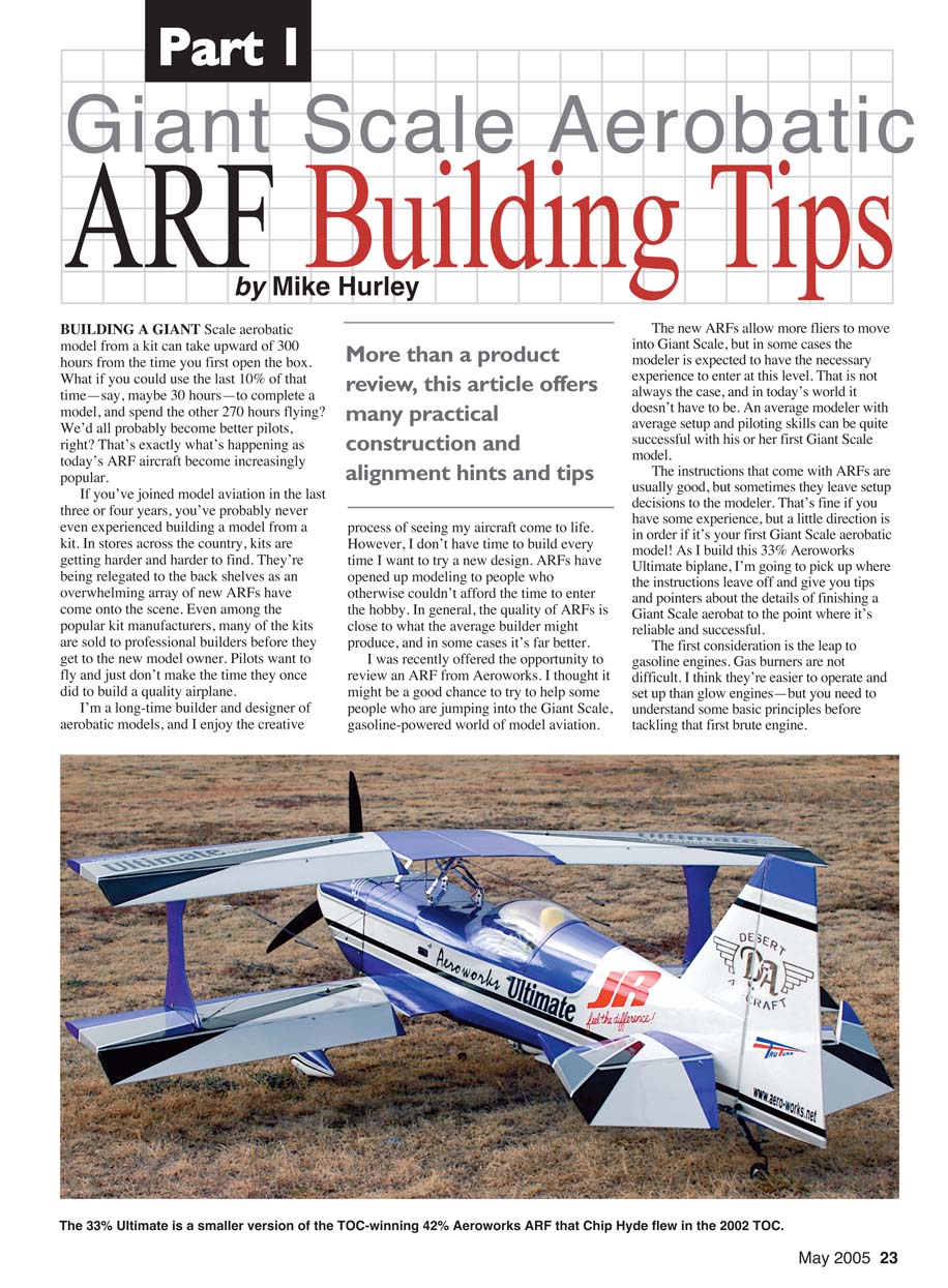
Part I Giant Scale Aerobatic ARF Building Tips
by Mike Hurley
BUILDING A GIANT scale aerobatic model from a kit can take upward of 300 hours from the time you first open the box. What if you could use the last 10% of that time—say, maybe 30 hours—to complete a model, and spend the other 270 hours flying? We'd all probably become better pilots, right? That's exactly what's happening as today's ARF aircraft become increasingly popular.
If you've joined model aviation in the last three or four years, you've probably never even experienced building a model from a kit. In stores across the country, kits are getting harder and harder to find. They're being relegated to the back shelves as an overwhelming array of new ARFs have come onto the scene. Even among the popular kit manufacturers, many of the kits are sold to professional builders before they get to the new model owner. Pilots want to fly and just don't make the time they once did to build a quality airplane.
I'm a long-time builder and designer of aerobatic models, and I enjoy the creative process of seeing my aircraft come to life. However, I don't have time to build every time I want to try a new design. ARFs have opened up modeling to people who otherwise couldn't afford the time to enter the hobby. In general, the quality of ARFs is close to what the average builder might produce, and in some cases it's far better.
I was recently offered the opportunity to review an ARF from Aeroworks. I thought it might be a good chance to try to help some people who are jumping into the giant-scale, gasoline-powered world of model aviation.
More than a product review, this article offers many practical construction and alignment hints and tips.
The new ARFs allow more fliers to move into giant scale, but in some cases the modeler is expected to have the necessary experience to enter at this level. That is not always the case, and in today's world it doesn't have to be. An average modeler with average setup and piloting skills can be quite successful with his or her first giant-scale aerobatic model.
The instructions that come with ARFs are usually good, but sometimes they leave setup decisions to the modeler. That's fine if you have some experience, but a little direction is in order if it's your first giant-scale aerobatic model. As I build this 33% Aeroworks Ultimate biplane, I'm going to pick up where the instructions leave off and give you tips and pointers about the details of finishing a giant-scale aerobat to the point where it's reliable and successful.
The first consideration is the leap to gasoline engines. Gas burners are not difficult. I think they're easier to operate and set up than glow engines—but you need to understand some basic principles before tackling that first brute engine.
The second issue is setting up and tuning a complex radio installation. What do you really need to be concerned about? What about redundancy? How about power needs for all of the heavy-duty (HD) and digital servos? What about linkages? How strong do they need to be?
The third area I'll touch on is building techniques. Yes, this is an ARF, but it still requires some model-building savvy to get the best from what is often a "good start" toward a finished model. Last, I'll evaluate the 33% Aeroworks Ultimate biplane and see if it rates your consideration.
Overall, the new breed of giant-scale aerobatics ARFs are great. They have kit-built-type construction and covering, and they are well designed, lightweight, and extremely economical. They are probably even less expensive than building a model from a kit when you factor in all of the glue, covering, materials, and hardware. And you still have all of that time and labor to consider!
However, if you are a nitpicky perfectionist who wants all of your airplanes to be absolute showstoppers and you don't care how much work it takes to get them into that state of perfection, an ARF is not for you. These models are factory-built in a production environment, and although the quality is fine for most of us, they are not perfect.
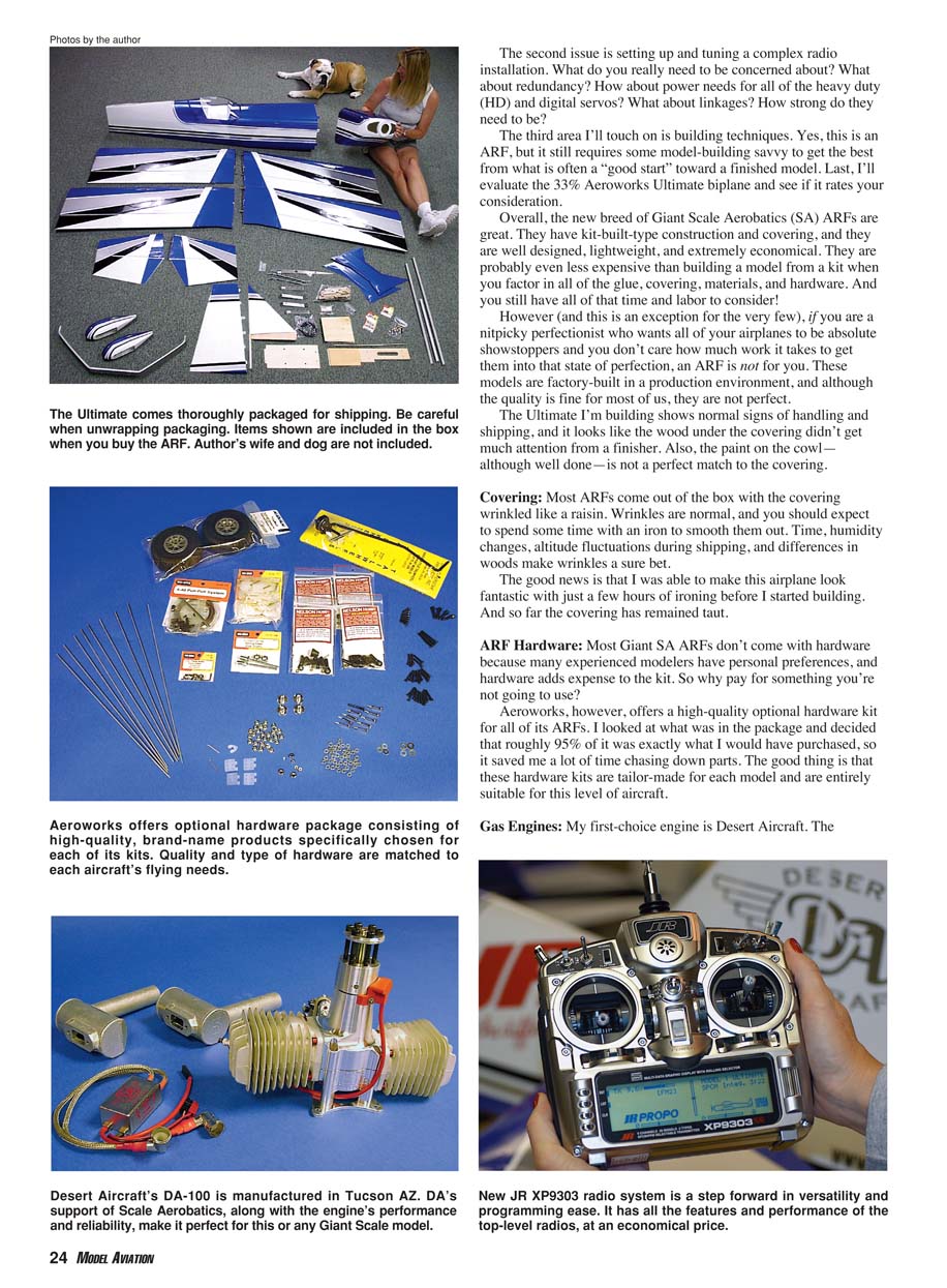
The Ultimate I'm building shows normal signs of handling and shipping, and it looks like the wood under the covering didn't get much attention from a finisher. Also, the paint on the cowl—although well done—is not a perfect match to the covering.
Covering
Most ARFs come out of the box with the covering wrinkled like a raisin. Wrinkles are normal, and you should expect to spend some time with an iron to smooth them out. Time, humidity changes, altitude fluctuations during shipping, and differences in woods make wrinkles a sure bet.
The good news is that I was able to make this airplane look fantastic with just a few hours of ironing before I started building. And so far the covering has remained taut.
ARF Hardware
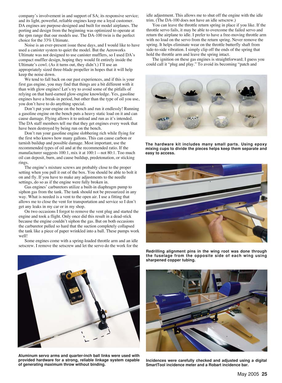
Most giant-scale aerobatic ARFs don't come with hardware because many experienced modelers have personal preferences, and hardware adds expense to the kit. So why pay for something you're not going to use?
Aeroworks, however, offers a high-quality optional hardware kit for all of its ARFs. I looked at what was in the package and decided that roughly 95% of it was exactly what I would have purchased, so it saved me a lot of time chasing down parts. The good thing is that these hardware kits are tailor-made for each model and are entirely suitable for this level of aircraft.
Gas Engines
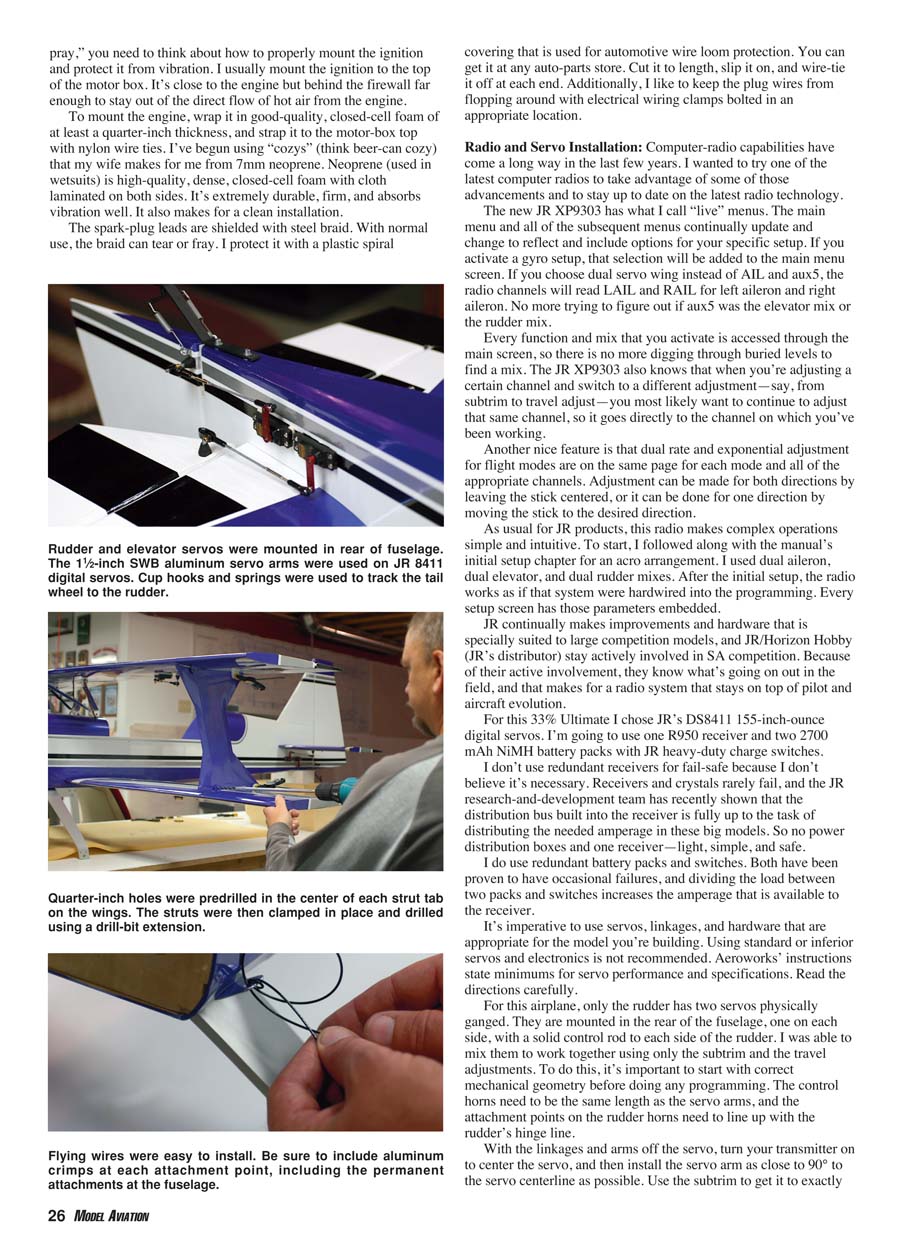
My first-choice engine is Desert Aircraft. The company’s involvement in and support of SA, its responsive service, and its light, powerful, reliable engines keep me a loyal customer. DA engines are purpose-designed and built for model airplanes. The porting and design from the beginning were optimized to operate at the rpm range that our models use. The DA-100 twin is the perfect choice for the 33% Ultimate.
Noise is an ever-present issue these days, and I would have liked to use a canister system to quiet the model. But the Aeroworks Ultimate was not designed to use canister mufflers, so I used DA’s compact muffler design, hoping they would fit entirely inside the Ultimate’s cowl. (As it turns out, they didn’t.) I’ll use an appropriately sized three-blade propeller in hopes that it will help keep the noise down.
We tend to fall back on our past experiences, and if this is your first gas engine, you may find that things are a bit different with it than with glow engines. Let’s try to avoid some of the pitfalls of relying on that hard-earned glow-engine knowledge. Yes, gasoline engines have a break-in period, but other than the type of oil you use, you don’t have to do anything special.
Don’t put your engine on the bench and run it endlessly. Running a gasoline engine on the bench puts a heavy static load on it and can cause damage. Flying allows it to unload and run as it’s intended. The DA staff members tell me that they get engines every week that have been destroyed by being run on the bench.
Don’t run your gasoline engine slobbering rich while flying for the first who-knows-how-many gallons. This can cause carbon or varnish buildup and possible damage. Most important, use the recommended types of oil and at the recommended ratio. If the manufacturer suggests 100:1, mix it at 100:1—not 80:1. Too much oil can deposit, burn, and cause buildup, predetonation, or sticking rings.
The engine’s mixture screws are probably close to the proper setting when you pull it out of the box. You should be able to bolt it on and fly. If you have to make any adjustments to the needle settings, do so as if the engine were fully broken in.
Gas engines’ carburetors utilize a built-in diaphragm pump to siphon gas from the tank. The tank should not be pressurized in any way. What is needed is a vent to the open air. I use a fitting that allows me to close the vent for transportation and service so I don’t get any leaks in my car or in my shop.
On two occasions I forgot to remove the vent plug and started the engine and took a flight. Only once did this result in a dead-stick because the engine couldn’t siphon the gas. But on both occasions the carburetor pulled so hard that the suction completely collapsed the tank like a piece of paper wrinkled into a ball. These pumps work well!
Some engines come with a spring-loaded throttle arm and an idle setscrew. I remove the setscrew and let the servo do the work for the idle adjustment. This allows me to shut off the engine with the idle trim. (The DA-100 does not have an idle setscrew.)
You can leave the throttle return spring in place if you like. If the throttle servo fails, it may be able to overcome the failed servo and return the airplane to idle. I prefer to have a free-moving throttle arm with no load on the servo from the return spring. Never remove the spring. It helps eliminate wear on the throttle butterfly shaft from side-to-side vibration. I simply clip off the ends of the spring that hold the throttle arm and leave the spring intact.
The ignition on these gas engines is straightforward; you could call it "plug and play." To avoid its becoming "patch and pray," you need to think about how to properly mount the ignition and protect it from vibration. I usually mount the ignition to the top of the motor box. It's close to the engine but behind the firewall far enough to stay out of the direct flow of hot air from the engine.
To mount the engine, wrap it in good-quality closed-cell foam of at least a quarter-inch thickness, and strap it to the motor-box top with nylon wire ties. I've begun using "cozys" (think beer-can cozy) that my wife makes for me from 7mm neoprene. Neoprene (used in wetsuits) is high-quality, dense, closed-cell foam with cloth laminate on both sides. It's extremely durable, firm, and absorbs vibration well. It also makes for a clean installation.
The spark-plug leads are shielded with steel braid. With normal use, the braid can tear or fray. I protect it with a plastic spiral covering that is used for automotive wire loom protection. You can get it at any auto-parts store. Cut it to length, slip it on, and wire-tie it off at each end. Additionally, I like to keep the plug wires from flopping around with electrical wiring clamps bolted in an appropriate location.
Radio and Servo Installation
Computer-radio capabilities have come a long way in the last few years. I wanted to try one of the latest computer radios to take advantage of some of those advancements and to stay up to date on the latest radio technology.
The JR XP9303 has what I call "live" menus. The main menu and all subsequent menus continually update and change to reflect and include options for your specific setup. If you activate a gyro setup, that selection will be added to the main menu screen. If you choose dual-servo wing instead of AIL and AUX5, the radio channels will read L AIL and R AIL for left aileron and right aileron. No more trying to figure out if AUX5 was the elevator mix or the rudder mix.
Every function and mix that you activate is accessed through the main screen, so there is no more digging through buried levels to find a mix. The JR XP9303 also knows that when you're adjusting a certain channel and switch to a different adjustment—say, from subtrim to travel adjust—you most likely want to continue to adjust that same channel, so it goes directly to the channel on which you've been working.
Another nice feature is that dual-rate and exponential adjustment for flight modes are on the same page for each mode and all of the appropriate channels. Adjustment can be made for both directions by leaving the stick centered, or it can be done for one direction by moving the stick to the desired direction.
As usual for JR products, this radio makes complex operations simple and intuitive. To start, I followed along with the manual's initial setup chapter for an "aero" arrangement. I used dial aileron, dual elevator, and dual rudder mixes. After the initial setup, the radio works as if that system were hardwired into the programming. Every setup screen has those parameters embedded.
JR continually makes improvements and hardware that is specially suited to large competition models, and JR/Horizon Hobby (JR's distributor) stay actively involved in SA competition. Because of their active involvement, they know what's going on out in the field, and that makes for a radio system that stays on top of pilot and aircraft evolution.
For this 33% Ultimate I chose JR's DS8411 155-inch-ounce digital servos. I'm going to use one R950 receiver and two 2700 mAh NiMH battery packs with JR heavy-duty charge switches.
I don't use redundant receivers for fail-safe because I don't believe it's necessary. Receivers and crystals rarely fail, and the JR research-and-development team has recently shown that the distribution bus built into the receiver is fully up to the task of distributing the needed amperage in these big models. So no power distribution boxes and one receiver—light, simple, and safe.
I do use redundant battery packs and switches. Both have been proven to have occasional failures, and dividing the load between two packs and switches increases the amperage that is available to the receiver.
It's imperative to use servos, linkages, and hardware that are appropriate for the model you're building. Using standard or inferior servos and electronics is not recommended. Aeroworks' instructions state minimums for servo performance and specifications. Read the directions carefully.
For this airplane, only the rudder has two servos physically ganged. They are mounted in the rear of the fuselage, one on each side, with a solid control rod to each side of the rudder. I was able to mix them to work together using only the subtrim and the travel adjustments. To do this, it's important to start with correct mechanical geometry before doing any programming. The control horns need to be the same length as the servo arms, and the attachment points on the rudder horns need to line up with the rudder's hinge line.
With the linkages and arms off the servo, turn your transmitter on or set it to center the servo, and then install the servo arms as close to 90° to the servo centerline as possible. Use the subtrim to get it to exactly 90°. Install the control rods and adjust them to fit both sides with the rudder centered. At this point everything is mechanically correct.
Bolt both control rods to the servo arms and one of the control rods to the rudder horn. Leave the other side unconnected. Move the rudder stick on the transmitter to the far end of travel, and use the travel adjust to align the unattached control rod to the rudder control horn. Do this for left and right deflection, and you're finished.
You can fine-tune this adjustment after it's all bolted together using an ammeter to detect any servo binding. Hangar 9 makes a tool for this called a Digital Servo and Receiver Current Meter.
Building the ARF
After ironing the covering and using an old soldering iron to cut open the covering where necessary, one of the first steps in the instruction manual is to glue the hinges in place. Since I opted for the hardware kit, I wanted to use the nylon-pin hinges included in the kit.
Be sure to allow for a gap of roughly 1/16 inch at the inboard edge of the aileron. I used a motorized slot cutter to make larger slots for the hinges and epoxied everything together. Be sure to lube the hinges where they join in the center so epoxy can't get into the moving parts.
Servos and Linkages
The next step was to install the servos and linkages. I started with the wings. Aeroworks inserts a string into the servo-lead tunnel so that you can pull your servo lead through without having to fish a wire through the hole. That's great—but in two of the panels the string was glued solid and wouldn't budge. I fished a wire through anyway and guided the servo leads in. Not a big deal. I used 12-inch HD servo extensions and tied the connection together using heavy-duty kite string to secure the knot.
I used the hardware provided in the optional kit to build the control rods, but instead of soldering a clevis on the servo side, I soldered on a threaded coupler from Du-Bro and used another ball end to mate to aluminum servo arms. This arrangement allows for more throw than a conventional clevis.
The linkage hardware included in the kit consisted of top-quality parts, sourced from the same manufacturers I would have used. The approach Aeroworks uses for giving you the appropriate hardware is commendable. These airplanes really do need quality at this level, and it's provided.
Fitting the Wings
I proceeded to fit the bottom wing to the fuselage. The incidence-location dowels in the root of the bottom wing halves didn't come close to lining up with the holes in the fuselage, so some adjustment had to be made. As long as I was at it, I figured I might as well check the incidence and set that up to fit just right.
The alignment pins were made from a brass tube fitted over wooden dowels glued into the root of the wings, so I couldn't just cut them off flush and drill new holes. The dowels had to come out. I noticed that the root rib was 1/4-inch thick, so I knew it would take some abuse, and I was able to remove the dowels with no damage to the wings. Then I glued some wooden plugs in the dowel holes.
The bottom wings fit into a slot in the side of the fuselage and mate to an inner box side. The slots in the fuselage were tight and the wings just fit. You could almost forget about the alignment pins as long as the wing was tight on the wing tube!
I checked the incidence on both sides, using the fit into the fuselage slots as the initial setting. The right side was perfect at 0°, and the left side was only a half-degree off. I adjusted the left slot and then used that setting to align and drill new holes for the new alignment pins.
After sanding the slot saddles to get a good incidence reading, I used a 12-inch piece of copper tubing with the end sharpened to drill the new holes into the root of the wings. I installed one wing half onto the fuselage and drilled the alignment pin holes from the other side using the alignment receptacles as a guide. Then I removed the wing half and epoxied new pins made from birch dowel rod in place.
The fit on the top wing was similar. I had to remove one of the pins in the wing root, align the wing, and redrill for the proper pin placement. If you ever have to do this, be careful not to drill too far and hit the balsa trailing edge or the spar. Use a piece of scrap wood to support the root while drilling.
I was surprised by how quickly I was able to make the adjustments, and the result is a perfect fit. At first this extra step seemed like more work than I wanted from an ARF, but the small amount of trouble was really worth the effort. This ARF’s wings fit as well as those on any custom aircraft I’ve built, and the incidence is perfect.
Struts and Flying Wires
The next step was to install the outer wing struts and the flying wires. This biplane’s outer struts were not predrilled for attachment. To drill the holes required in the strut tabs on the wings, you need either a long 18 x 1/4-inch drill bit or a drill extension. I found an extension at the tool store for six bucks.
I drilled the holes in the tabs on the wing to ensure that they were centered. I aligned the struts on the inside of the tabs to fit the wings and clamped them in place. I used the tabs as a fixture and drilled the struts. The struts were assembled on the outside of the wing tabs.
Biplane flying wires seem to be such a hassle, especially for field assembly. But Aeroworks has done a fantastic job of designing a way to assemble the outer struts and flying wires in a quick and easy process.
There are four wires on each side of the model. The wires are permanently attached at two points on the fuselage, two wires per point. There are two tabs on each upper and lower wing half. The struts and the wires attach to the tabs. Be sure to put crimps at the permanent points and the turnbuckles. You simply push a slotted and drilled pin through the outer struts into the wing tabs, and connect a flying-wire turnbuckle to the pin with a key pin. Four points at each strut, and you’re finished!
Mike Hurley 11542 Decatur Ct. Westminster, CO 80234 [email protected]
Manufacturers
- JR radio equipment
- Horizon Hobby Inc.
- 4105 Fieldstone Rd.
- Champaign, IL 61822
- (217) 352-1913
- Toll-free: (800) 338-4639
- Fax: (217) 355-1552
- www.horizonhobby.com
- Engine, mufflers, propeller
- Desert Aircraft
- 1815 S. Research Loop
- Tucson, AZ 85710
- (520) 722-0607
- Fax: (520) 722-5622
- www.desertaircraft.com
- 4-inch Ultimate spinner
- Tru-Turn Precision Model Products
- 100 W. 1st St.
- Deer Park, TX 77536
- (281) 479-9600
- Fax: (281) 479-9090
- www.tru-turn.com
- 33% Ultimate biplane
- Aeroworks
- 401 Laredo St., Suite D
- Aurora, CO 80011
- (303) 366-4205
- Fax: (303) 366-4203
- www.aero-works.net
(Editor’s note: Next month we will present Part 2 of this article, which will contain even more tips and techniques for assembling one of these behemoth ARFs.)
Transcribed from original scans by AI. Minor OCR errors may remain.

