


Gipsy Moth
Unable to find "Gipsy Moth" on the scanned page(s)
I inspected the scanned page(s) you provided. They do not contain the "Gipsy Moth" article. Instead, the images and OCR text correspond to other content (AMA Headquarters dedication/photos, ads, and event photos), so I cannot extract or continue "Gipsy Moth" from those scans.
What I found
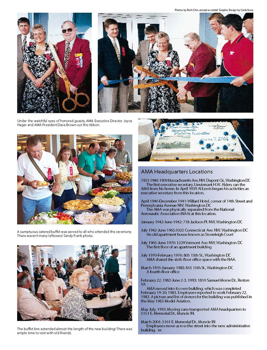
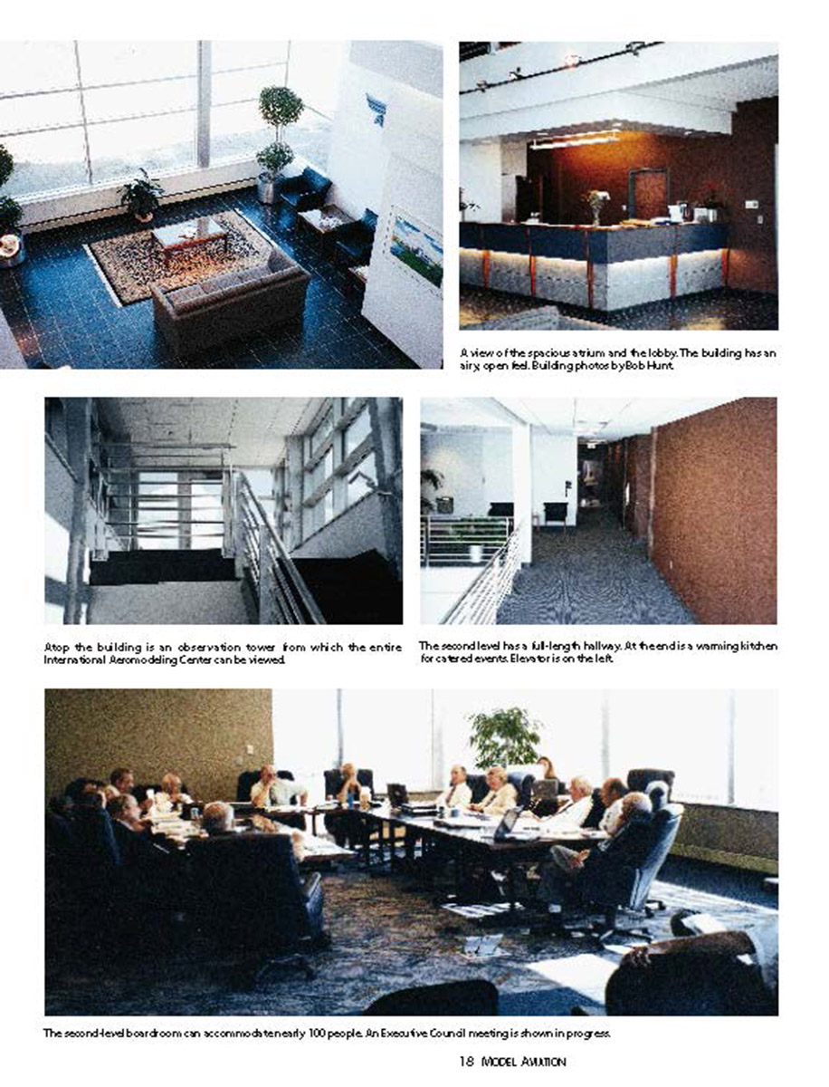
- "New Headquarters Building Dedication" (AMA Headquarters) article and photos/captions.
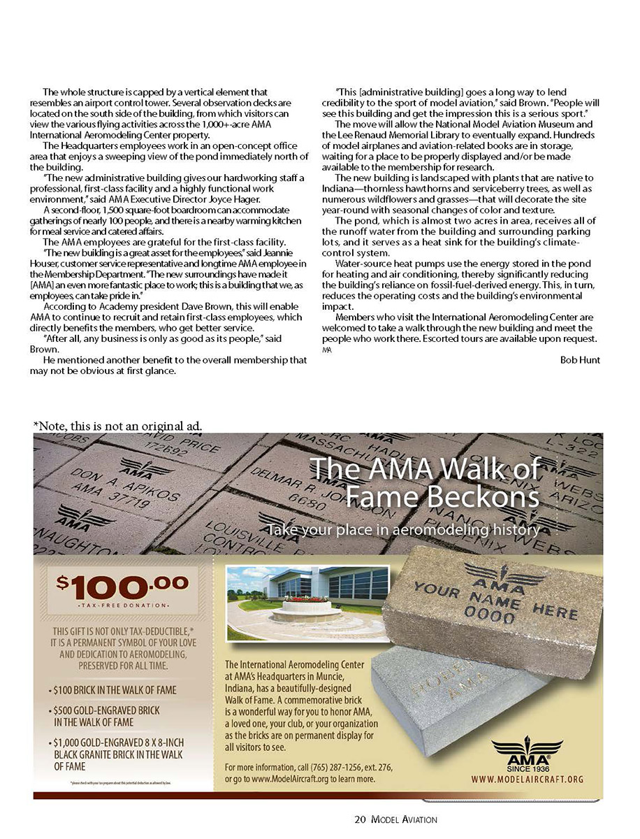
- An AMA Walk of Fame advertisement/page.
- A “Our Very Best to You, and Thanks!” (The ZAP Gang) advertisement.
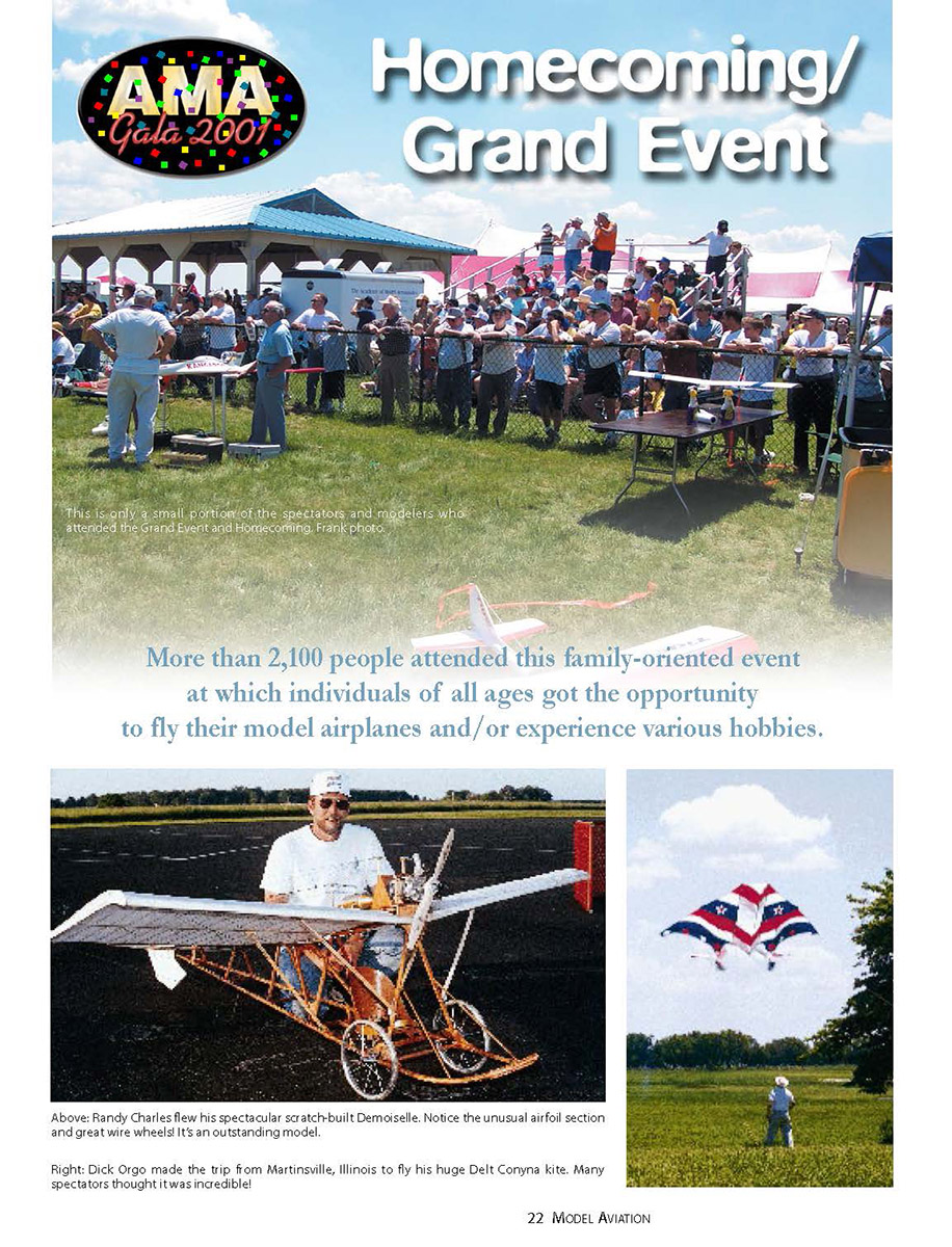
- AMA Homecoming / Grand Event photos and related ads.
Options — choose one and I’ll proceed
- Upload the correct scanned page that contains the "Gipsy Moth" page you want extracted (preferred). I will extract and clean the article text from that image.
- Allow me to extract and correct the article that actually appears on the provided page(s) (e.g., the AMA Headquarters dedication/photos or the ads). I will clean and format that content.
- Have me clean up and correct the OLD OCR "Gipsy Moth" text you previously provided (I will fix OCR errors and hyphenation based on that text rather than using a scan).
Next step
Tell me which option you want and, if applicable, upload the correct scanned page (please indicate the page number if known). I’ll proceed as instructed.
Transcribed from original scans by AI. Minor OCR errors may remain.

