
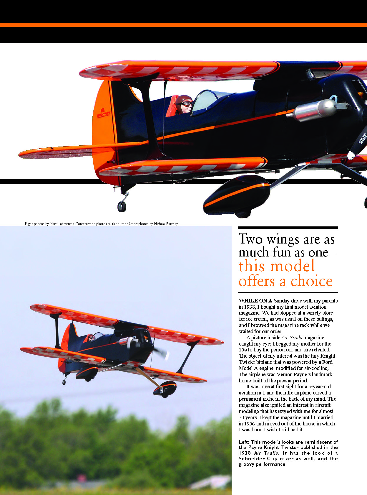
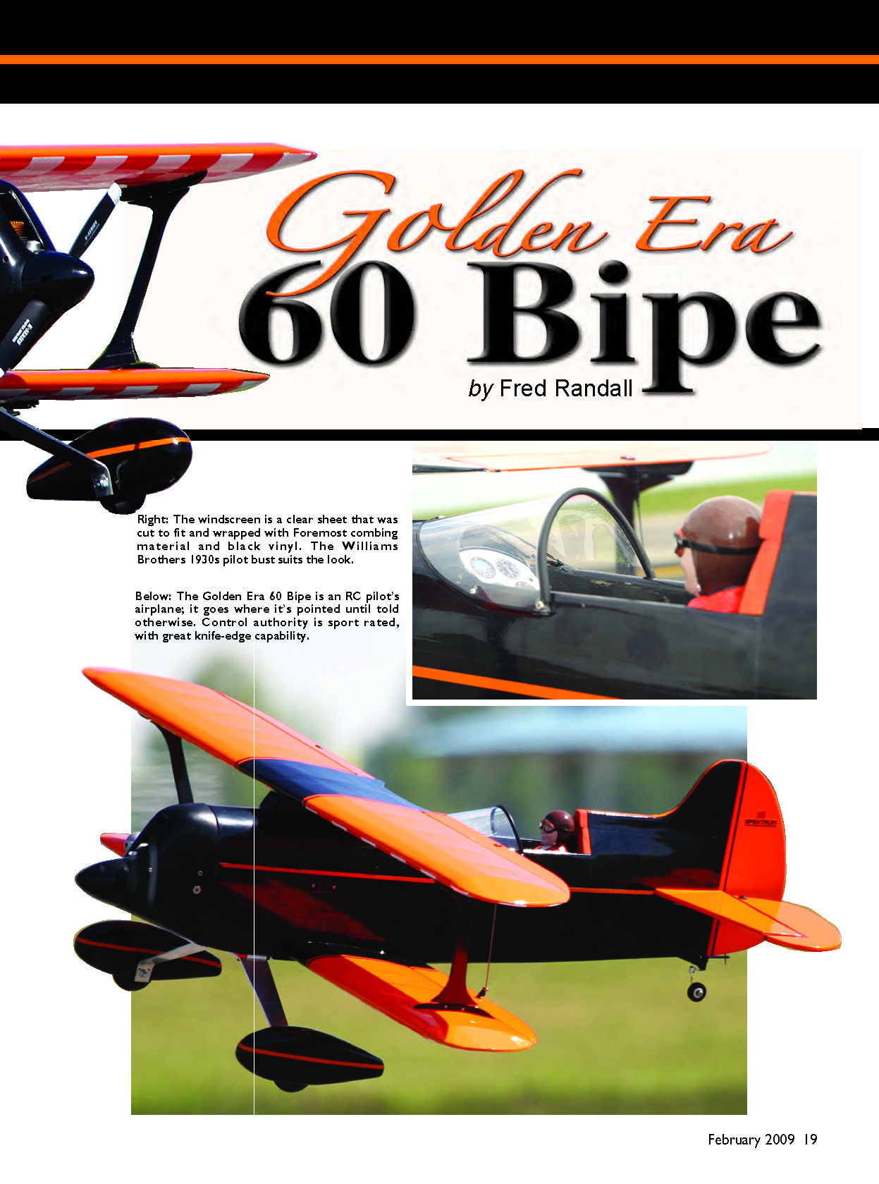
Two wings are as much fun as one — this model offers a choice
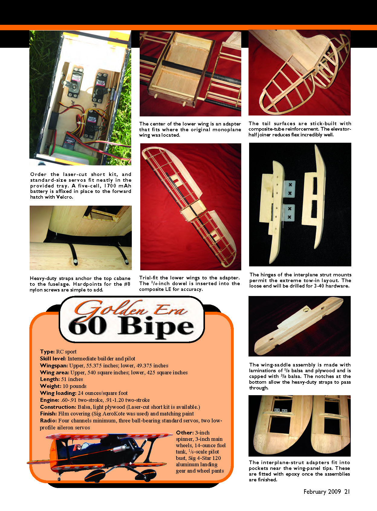
- Type: RC sport
- Skill level: Intermediate builder and pilot
- Wingspan: Upper, 55.375 inches; lower, 49.375 inches
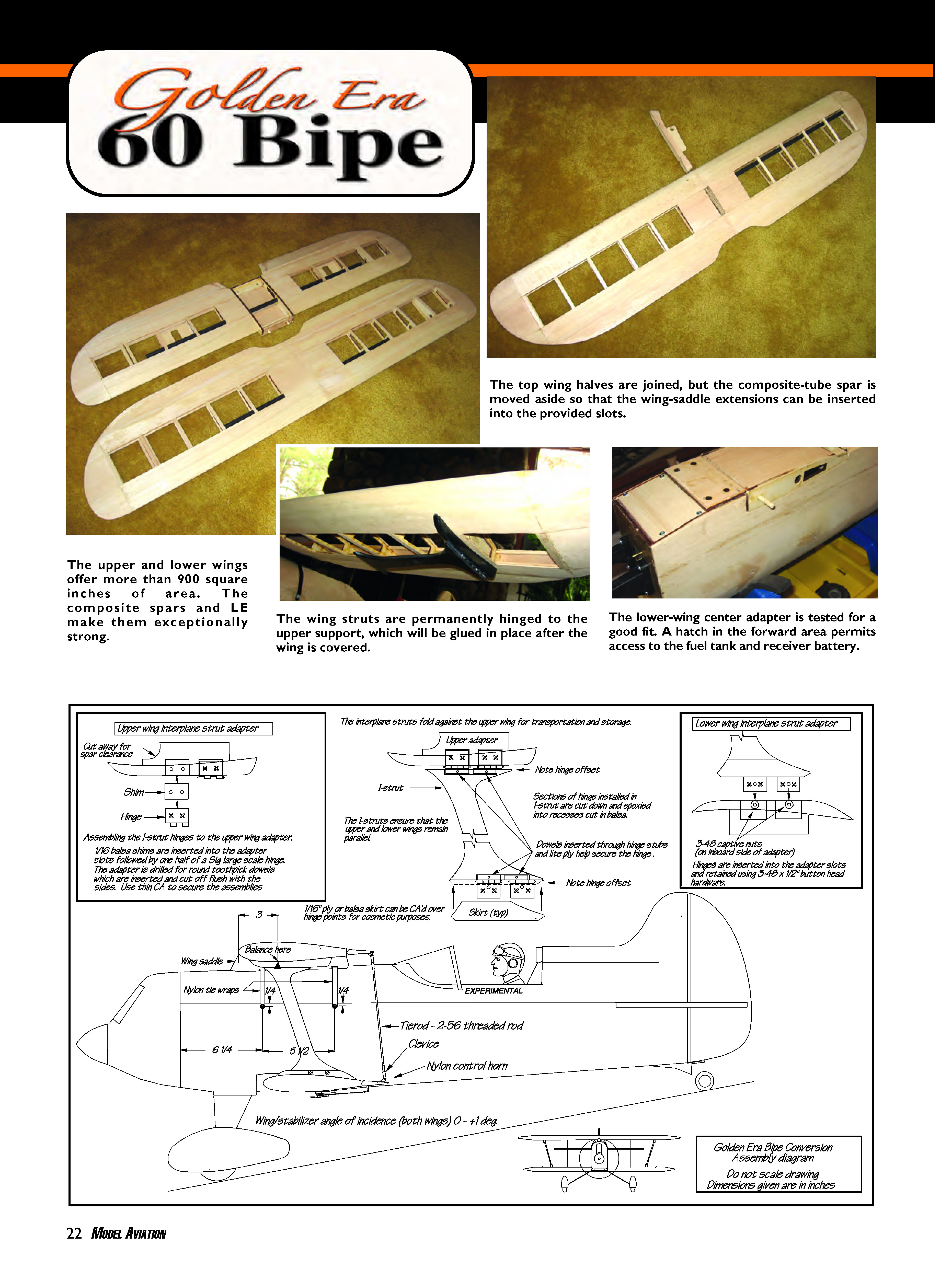
- Wing area: Upper, 540 square inches; lower, 425 square inches
- Length: 51 inches
- Weight: 10 pounds
- Wing loading: 24 ounces/square foot
- Engine: 0.60–0.91 two-stroke, 0.91–1.20 two-stroke
- Construction: Balsa, light plywood (Laser-cut short kit is available.)
- Finish: Film covering (Sig AeroKote was used) and matching paint
- Radio: Four channels minimum, three ball-bearing standard servos, two low-profile aileron servos
- Other: 3-inch spinner, 3-inch main wheels, 14-ounce fuel tank, 1/6-scale pilot bust, Sig 4-Star 120 aluminum landing gear and wheel pants
Background
While on a Sunday drive with my parents in 1938, I bought my first model aviation magazine. We had stopped at a variety store for ice cream, as was usual on these outings, and I browsed the magazine rack while we waited for our order.
A picture inside Air Trails magazine caught my eye; I begged my mother for the 15¢ to buy the periodical, and she relented. The object of my interest was the tiny Knight Twister biplane that was powered by a Ford Model A engine, modified for air-cooling. The airplane was Vernon Payne’s landmark home-built of the prewar period.
It was love at first sight for a 5-year-old aviation nut, and the little airplane carved a permanent niche in the back of my mind. The magazine also ignited an interest in aircraft modeling that has stayed with me for almost 70 years. I kept the magazine until I married in 1956 and moved out of the house in which I was born. I wish I still had it.
I have no doubt that, with better servos and long throws, the bipe would give a good aerobatic account of itself at anybody's club field.
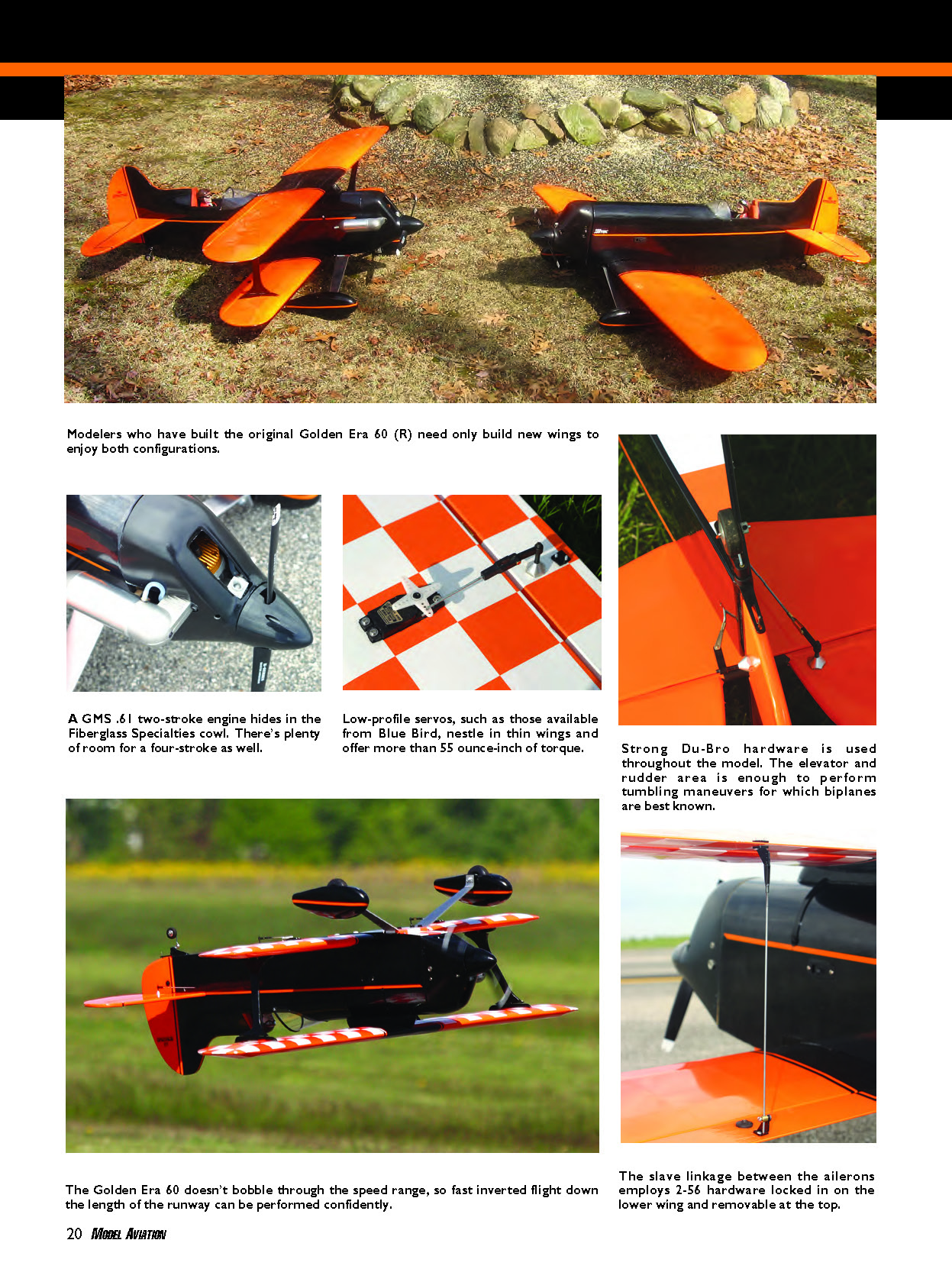
This build is predicated on the concept of using one fuselage and tail section as a basis for two aircraft: a monoplane and a biplane. I designed the monoplane first, and I didn't want to extensively modify the fuselage to convert the Golden Era 60 to a biplane. That decision led to the use of an adapter, which allows the narrower biplane lower wing to fit into the monoplane's wing recess. The adapter is also responsible for the wing-saddle setup for the upper wing mount. The Golden Era 60 is convertible with no readily observable compromises.
This article covers only those assemblies and procedures necessary to convert the Golden Era 60 to a biplane and back to a monoplane. Field conversion should take only minutes. Simply head to the field, choose your set of wings, and fly.
If you are interested only in the biplane, feel free to redesign the wing mountings, struts, etc. One of the neat things about scratch building is the option of doing it your way. If you do, I'd love to see the result.
CONSTRUCTION
As with all scratch builds, it is best to have all components fabricated and ready for assembly. You should also have a completed fuselage available for parts fitting.
I took great care, when making the drawings, to ensure that the holes for pegs, spars, wing LE, etc., are accurate within 1/32 inch. But the process of duplicating prints can create small errors. It is the builder's responsibility to ensure that all critical drilled holes are accurate for size and location.
When using the short kit, you'll need to scuff the burned area where cement, either epoxy or cyanoacrylate, is being applied. Adhesives bond poorly to a charred surface. It's unnecessary to remove all traces of brown; sand enough to get loose surface scale off. Don't remove so much material that the parts fit is impaired. Using the preceding tips, I have not had a glue joint fail using the laser-cut parts.
In the remainder of the article, unless otherwise noted, "cyanoacrylate" will mean the medium adhesive and "epoxy" will mean the 30-minute variety.
Adapter
This tool for the lower wing adapter provides a means to mount the narrower lower wings into the existing Golden Era 60 wing recess. The adapter is an uncomplicated structure consisting mainly of a few pieces of 1/4-inch plywood, scrap balsa, and basswood spar material.
The adapter's fit is critical to the angle of incidence and the alignment of both the upper and lower wings. If the finished assembly can't be made to comply with any of the conditions in the following paragraphs, it's best to start over.
Epoxy is used for adapter construction. Employ a lower wing rib as a pattern, and ensure that the forward peg hole and the spar holes in the adapter sides are coincident with the corresponding holes in the wing rib. In addition, ensure that the pegs in the adapter front will line up with the holes in the fuselage former F1 assembly.
Using the adapter diagram on the print as a guide, epoxy and clamp together the adapter sides, front, and back. Make sure that the assembly is square.
Install the wing mounting plate in the slot provided. It should be flush with the bottom of the assembly. Epoxy the 1/4-inch pegs into the front of the adapter; they should protrude approximately 3/8 inch and have a slight chamfer at the exposed ends. Cut the 1/4-inch LE positioning dowel to extend past the adapter by 1 inch on either side. Do not add epoxy at this time.
Check the assembly's fit. The pegs should engage the holes in fuselage former F1, and the adapter sides should fit snugly against the wing recess in the fuselage sides. If the fore/aft fit is too tight, remove some material from the rear of the adapter.
With the adapter temporarily installed in the fuselage, insert the composite spar through the opening in the adapter. Use a large square to ensure that the spar extends at right angles to the fuselage sides.
When the fit is satisfactory, install the 1/8-inch square adapter bottom support, recessed 3/32 inch and following the contour. Mount the 3/32-inch balsa bottom; it should be flush with the bottom of the adapter. I used a 1/8 x 1/4-inch basswood crosspiece to help support the balsa.
The accompanying pictures should clarify things.
Lower Wings
The lower wing panels are identical as assembled over the plans. Protect the plans with waxed paper, since both the left and right lower sections will be constructed over them.
Cut a piece of 1/8 x 1/4-inch basswood for use as a bottom middle spar, and secure it in place on the plans. It will be used as a guide to ensure proper rib placement.
The lower ribs are the same. Using cyanoacrylate and a small square, cement them in place at their stations on the plans. The break-off tabs should be flush against the building board.
When the cyanoacrylate has set, install the two 1/8 x 1/4-inch top spars and the 1/8-inch square spar at the top rear. Cut a piece of 0.317-inch composite tubing to length, and use cyanoacrylate to adhere it in place at the wing LE. Its ends should be flush with the outside surface of the center and end ribs.
Remove the wing from the plans and install the remaining spars. Cut a length of 3/8-inch square balsa TE to size, and shape it as the plans show. A razor plane and sanding block will make short work of this task. Make a TE for the left wing and set it aside.
Before performing the next steps, note that the two inboard ribs on the lower wings are spaced closer than the remaining ribs. Don't make the mistake of attaching the wingtip to the wrong end of the wing.
Cyanoacrylate-glue the TE to the wing and secure the wingtip. Ensure that the wingtip bisects the wing center and extends horizontally, at right angles to the ribs. Cut and install the spar extensions, beveling the ends for a flush fit against the wingtip.
Snap off the rib stubs, and then sand the area smooth. The wing should be symmetrical, with no top or bottom. Decide whether it will be a right or a left wing; mark it in several places.
The false ribs used for the I-strut adapters need to be installed. Using a scrap piece of 1/8-inch plywood as a temporary spacer to establish a slot, cyanoacrylate-glue them in as indicated on the plans.
Repeat the previous wing-building instructions to construct the opposite wing. The only difference will be when you mount the servo plates and the interplane strut mounts. Be careful; you cannot imagine how easy it is to find yourself with two right or two left wings.
Cut stiffeners from scrap spar material for the servo plates, as shown on the plans diagram, and adhere them in place with cyanoacrylate. The side rails provide a gluing surface for attaching the plate to the ribs, and the transverse pieces provide a secure seat for the servo mounting screws.
Test-position the servo plates on the bottom of the wings. Make sure they don't interfere with insertion of the main spar. When satisfied with the fit, epoxy the servo plates in place as flush as possible with the bottom of the ribs.
Because of the thin wing, it's necessary to use low-profile servos. I recommend the Blue Bird BMS-706. For roughly a $20 street price, you get dual ball bearings and 65 ounce-inches of torque. Standard servos almost fit, but who needs a lump in the wing covering?
At this point, insert a 0.505-inch main spar through the adapter and into the wings. Make sure that the LE positioning dowel engages the 0.317-inch composite tubing. If it does not, reshape the peg hole in the adapter fore or aft for a proper fit. The vertical position must remain unchanged. When satisfied, cyanoacrylate-glue the dowel only to the adapter.
The lower wings will not be permanently mounted to the adapter until they are planked. The strut adapters have been added and the wings have been covered.
Shape the ailerons. Using the plans as a pattern, cut the 3/8 x 2-inch tapered stock to a shape that conforms to the wing TE. Install hinges after you have applied the planking.
Upper Wings
Remove the lower-wing plans from the building board, and secure the upper-wing plans in their place. The procedure for building the upper wings is identical to the procedure for building the lower, less the servo mount.
After removing the wing halves from the plans, decide whether or not you want hinged ailerons on the upper wings, as are on the lower. It is also time to cyanoacrylate-glue a 1/4 x 6-inch dowel into one LE at the wing root. Allow 3 inches to protrude from the LE. The dowel will slide into the opposite wing's LE as an alignment aid when they are joined.
There is generous aileron area on the lower wing for general sport flying, but I chose to employ working ailerons on both wings. I initially had the ailerons fixed to the upper wings, as shown in the photos, but I cut the upper ailerons free before covering. This decision was prompted by discussions with friends and, notably, a suggestion from a magazine editor.
I have used a simple method to link the upper and lower ailerons. The link is positioned directly behind the aileron servo for positive operation. Many biplanes' slave links are behind the interplane struts; however, because of the I-struts' outboard location, that wasn't a prudent solution with this model.
Follow the plans for aileron shaping and cutting. If the upper ailerons are going to be fixed, you can adhere them to the TE with cyanoacrylate after planking. Otherwise, cut the ailerons as the plans indicate and shape the LE for hinging.
This decision is reversible. The fixed ailerons on the upper wings can easily be cut free and hinged.
Wing Planking
The upper wings need 1/16 x 6 x 24-inch balsa for LE planking; the lower wings require 1/16 x 5 x 24-inch balsa. If you are gluing two pieces to get the width, use a 2- and a 4-inch (or 3-inch) sheet to prevent the sharpest bend from being at the glue joint.
Spray Windex generously to make the balsa pliant enough to bend around the LE's tight radius. After it soaks for several minutes, you should have no trouble making the bend.
The remaining planking is effortless. Except for the wingtip LE, no further soaking should be necessary. Capstrips are used on both wings. I like the appearance, and they add little weight. I also planked the entire wingtips. (Doing so or not is the builder's choice.)
After planking is complete, use a few small spots of planking cyanoacrylate to temporarily attach the ailerons to both sets of wings. Shape the ailerons to blend with the wing TEs. After shaping, use cyanoacrylate debonder or a hobby knife to remove the ailerons.
This is a good time to cut aileron hinge slots. I chose leaf hinges rather than the typical cyanoacrylate type. I used four on each side, spaced to avoid the ribs.
When you have completed the upper wing halves except for covering, join them. Install—but do not epoxy—the 0.505-inch spar. It must be free to slide past the root rib to the wing saddle that will be inserted later. Use the peg in one LE and the composite spar for alignment, and epoxy and clamp the wing halves together.
Upper Wing Saddle
Since making as few modifications as possible to the original fuselage was a priority, I had a problem attaching the upper wing. I was concerned that a balsa-and-light-plywood "N"-style cabane-strut system might not be strong enough, and I didn't want to resort to aluminum; I'm not much of a metalworker.
The answer came to me as I worked on my ham radio tower. I had some large UV-proof tie-wraps I used to attach a heavy switchbox to one of the tower legs. The old Knight Twister had a pylon between the upper wing and the fuselage; it would be simple to attach the wings using a pylon or wing saddle and these heavy-duty straps. Better still, it would require only four small holes in the fuselage to hold the straps in place.
The drawings on the plans show parts outlines and materials for the wing saddle. It is attached permanently to the upper wing and uses two sections of industrial-strength nylon tie-wrap to secure the saddle to the fuselage using nylon bolts.
The tie-wraps are inexpensive and extremely strong. I used the black Leco Plastics L-48-175 wraps, which have a 175-pound tensile (pull) strength. Although holes have to be drilled in the ties, they are suitable for the job. They are available at any good hardware or construction-equipment store.
The wing saddle is built up using several pieces of balsa and plywood. Some shaping and notching is necessary but shouldn't present a problem to an experienced builder. The rectangular holes in the plywood are best made by drilling the corners and then using a Dremel or scroll saw to cut away the material between the drilled holes.
The biplane-conversion short kit includes laser-cut plywood saddle parts: one 1/4-inch plywood piece for the core and two 1/8-inch plywood outer pieces with blades that go into the upper wing and engage the spar. The two 3/8-inch balsa finish pieces are left to the builder to fabricate.
The balsa parts have a channel for the straps that terminates in a rectangular opening at the lower, outside edge. The easiest way to make the balsa parts is to shape the outline and then cut notches in the bottom. Use a rotary tool to rout out the inside to allow for passage of the straps.
Align the five pieces and clamp them together. The top of all four pieces should be flush. The holes in the two outer plywood parts are slightly larger and lower, to allow for the curve in the retaining straps.
While the parts are clamped together, test-fit a length of strap. The tie-wraps are snaked through the rectangular slots in the saddle assembly. These should be able to pass through the wing saddle and slide freely. Use pliers to curve the end of the strap; that should make it easier to fish through the wing saddle.
When satisfied with the fit, remove the straps and epoxy all five parts together, clamping them until set. Ensure that the strap holes remain clear. Use a file or a rotary tool to contour the bottom to closely match the curve of the fuselage, and then round the front and rear.
Finish the entire saddle per your taste. Then insert the straps, leaving roughly 6 inches extending on either side of the saddle, front and rear.
Make the holes in the fuselage for the #8 bolt hardware. The holes should be large enough for the 8-32 captive nuts to be epoxied inside the fuselage.
The front mounting holes in the fuselage should be just aft of former F1 and 1/4 inch below the junction of the curved top and the fuselage sides. The rear set of holes is 5-1/2 inches farther aft.
Carefully center the wing saddle, hold it in place with masking tape, and mark and drill the straps for 8-32 nylon screws. It's a good idea to mark center with a bit of striping tape as a permanent alignment aid.
Be careful to ensure that the straps will hold the saddle tightly against the fuselage. The tie-wraps will not stretch, so the position of the holes is critical.
Glue a felt pad to the bottom of the saddle to prevent damage to the fuselage. Install the pad after drilling the holes. It will take up any slack in the straps and ensure a tight fit. Use a couple layers of felt if necessary.
Cut 1/8-inch slots in the planking on the bottom of the upper wing for the wing-saddle blades. Cover the area with a 4-inch strip of film to eliminate the need for meticulous trimming around the wing saddle when covering the wings. Remove the film from the area of the slots.
Slide the composite main spar all the way to one wingtip, and then apply epoxy to the inside of the blades extending from the wing saddle. Use a couple strips of masking tape applied to the wing bottom to prevent the epoxy from migrating.
Insert the blades into the slots, sandwiching the root ribs. Seat the wing saddle snug against the wing and center the composite spar, sliding it through the holes in the blades.
Apply epoxy to the spar at several rib intersections, securing it permanently. Put some weight on the bottom of the saddle to hold it firmly against the wing, and set it aside to cure.
Interplane Struts
The interplane struts consist of six separate pieces: four fixed adapters that are fabricated and epoxied to the upper and lower wings after covering, and two struts that are permanently hinged to the top wing adapters using Sig Giant Scale hinges.
The upper and lower wing I-strut adapters are made from 1/8-inch plywood. Assemble them according to the plans, sand them smooth, and check for fit in the appropriate slots.
The interplane struts are made from 1/8-inch light plywood and 1/8-inch balsa. Use the plans pattern to make two pieces of each material. It is important to have the balsa lamination inboard on each side.
Adhere the parts with cyanoacrylate, and then sand the edges to a rounded contour. Finish the struts and adapters with fuelproof paint.
Using the assembly drawing as a guide, epoxy hinges in the fixed upper adapter and the I-struts. You can fill the recesses in the I-struts with balsa filler after hinging, or you can make a skirt to conceal the hinge mechanism. In any case, be sure that the hinges can move a few degrees in the direction they need to go, and peg the hinge stubs recessed in the I-struts.
The free part of the hinges on the bottom of the I-struts extends into the fixed lower strut adapter during field assembly, and two 3-48 x 1/2-inch button-head screws secure them in place on each side.
With the wings covered, cut the strut-adapter slots in both wings. The upper adapter should have the I-struts permanently installed. Make sure that the hinges are free enough to let the struts fold inboard, flat against the wing, for storage and transportation.
Use epoxy to install the strut adapters in the lower wing. Ensure that they're properly oriented. This completes the building portion of the Golden Era 60 biplane conversion.
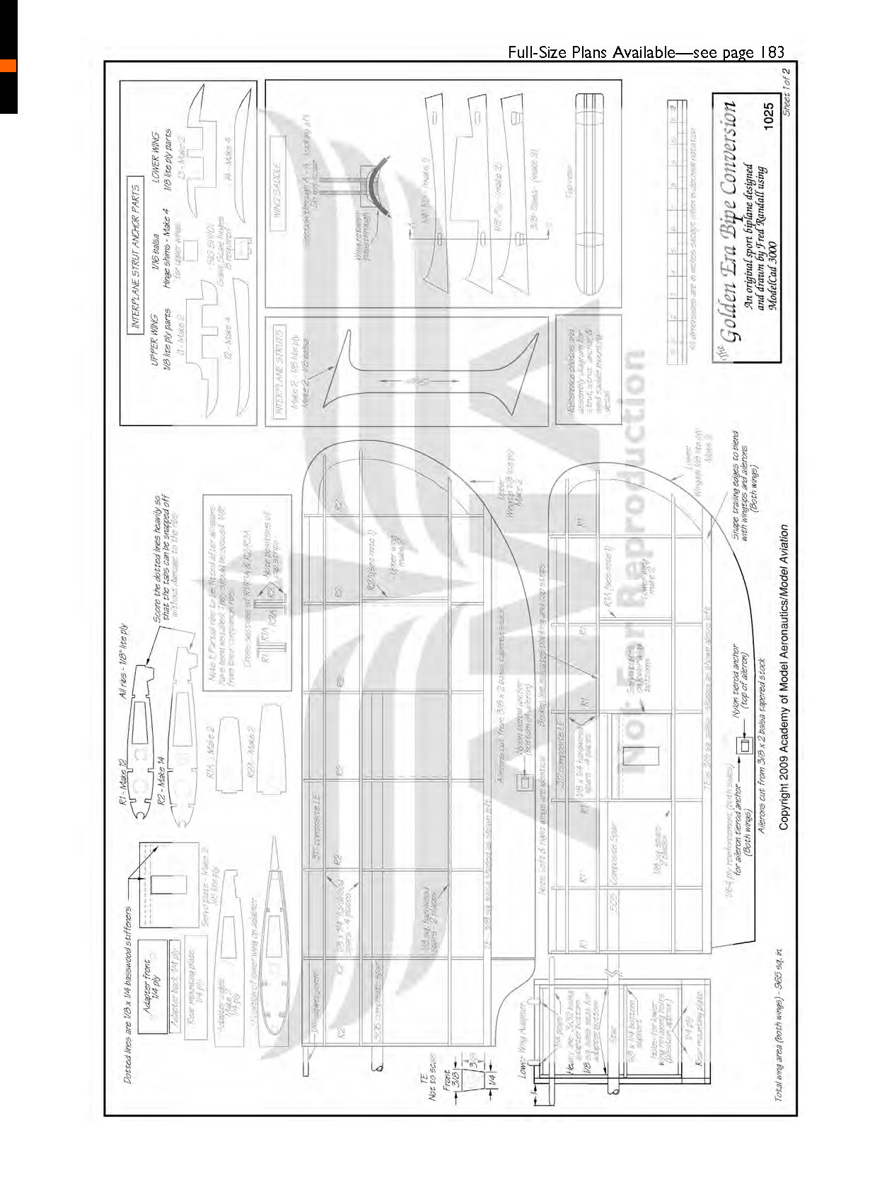
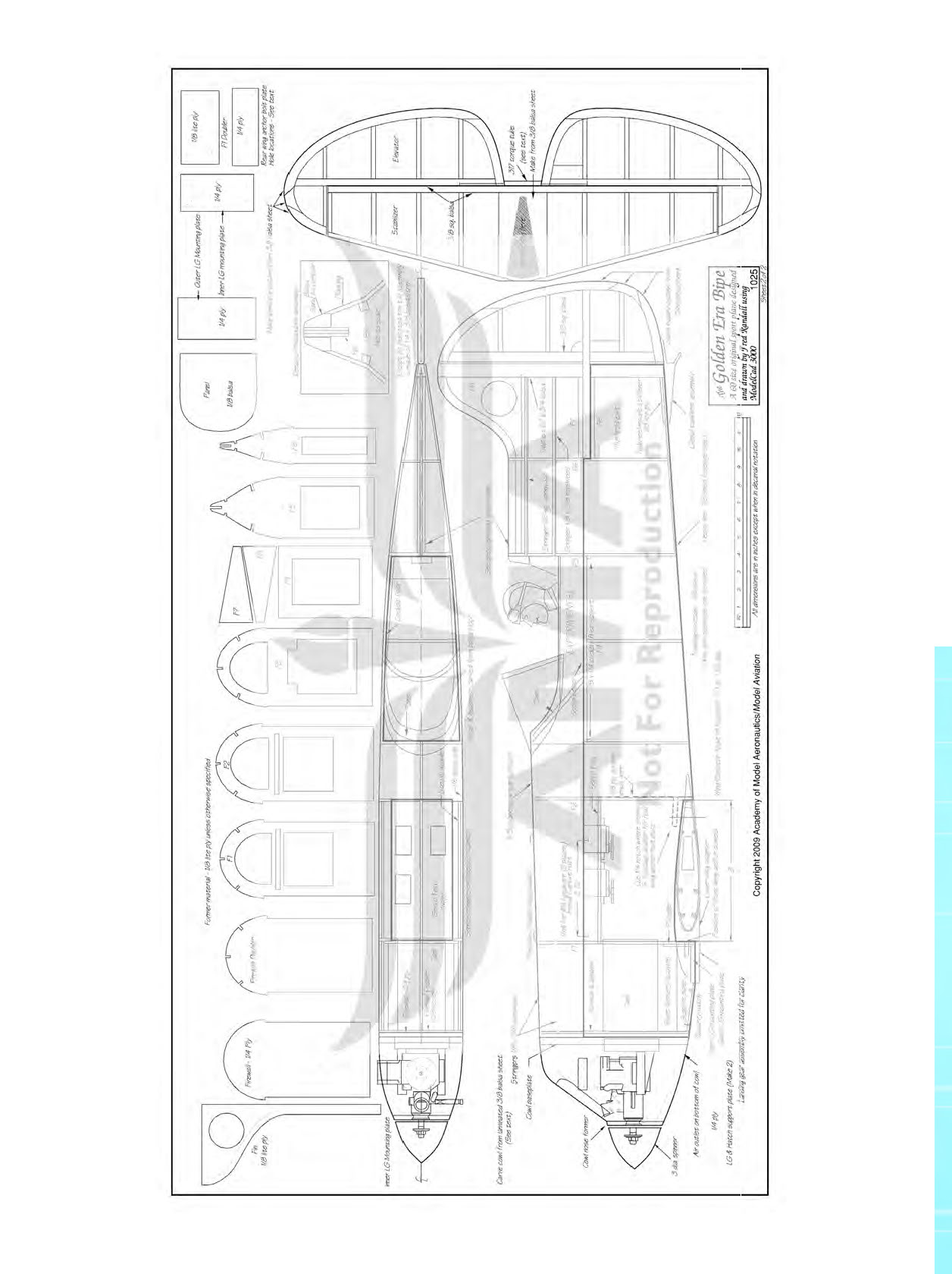
An assembly diagram is included on the plans.
Flying
Ground-handling the Golden Era 60 biplane is similar to driving a motor home: just set the cruise control and go make a sandwich in the galley. It's that assuring and easy.
The long tail moment and wide landing gear do everything to keep the taxi stuff friendly. Even the high-speed run before liftoff requires little or nothing to be done with the rudder. When this model rolls down the runway at a speed where it looks like it should fly, haul back on the elevator and up it goes, straight and true.
The GMS 0.61 engine, which this airframe is built around, is a nice sport power plant for such a model. It's reminiscent of the "old school" power philosophy; the airplane flies on the wing and not on the propeller.
As noted during testing, the Golden Era can handle, and in some cases deserves, the power a 0.91 two-stroke or four-stroke engine could give it. If that's what you have in your engine drawer, by all means put it in.
With its 900 square inches of wing area, this model can cruise around comfortably at 65% power. Coordinating the turns is unnecessary when the speed is kept up, but in the wind it likes slight rudder mixed in the same direction as the aileron input. Elevator in the turns, whether they're inside or outside, can crank the bipe around as tightly as the pilot wants, given sufficient engine power.
The rudder is very effective, which, given its size ratio comparison with the rest of the surfaces, was a huge yet pleasant surprise. I set the high-rate travel to maximum deflection and found it to be extremely touchy for normal flight but the heart of the tumbling trickery that this model has in its bag of magic.
For the most part, 50% throw in the rudder plus approximately 30% exponential was a decent setup. That way, the stall turns can be done in a tight half circle.
A large amount of rudder input can tuck the nose toward the landing gear, so watch during landing if heading corrections are required. In knife-edge flight, the rudder corrections want to naturally roll the model back to level flight, and it's already pushing away from the canopy. For the most part, the pilot can hold these corrections in for a wicked-cool knife-edge pass down on the deck, but a P-mix or two into the rudder will fix the habit completely.
The twin ailerons are a delight; both wings work together, rather than one wing with ailerons having to overcome the drag of the other. Little deflection is needed for normal flying, and the ailerons' movement requires no differential mixing because their travel is minimal.
Point rolls are possible and have the crispness we see at air shows with the Pitts biplanes. That includes the "wow" factor.
Landing the Golden Era biplane is almost easier than landing a trainer. Because it flies where the pilot points it, bringing the model home is a matter of "X" marks the spot. With a throttle setting of roughly 50%, this airplane sets itself into a natural glide slope; all the pilot needs to do is gently pull on the up-elevator before touchdown and ease the throttle back to idle.
Make the Golden Era biplane your everyday flier. I've tested it in calm and hurricane-like conditions, and I was phenomenally impressed by how solidly it performed.
Thanks for the airplane, Fred. I'm having a blast!
Fred Randall [email protected]
Sources:
- Payne Knight Twister information, full-size home-built plans: www.steenareo.com
- Creative Hobbies — (508) 473-8259, www.creativehobbies.net
- Composite tubing: Kite Studio — (800) KITE-991, www.kitebuilder.com/catalog/index.php
- AMA Plans Service — (800) 435-9262, ext. 507, www.modelaircraft.org/plans.aspx
- Fiberglass Specialties — (479) 359-2259, www.fiberglassspecialtiesinc.com
- National Balsa Co. — (413) 277-9500, www.nationalbalsa.com
- Balsa USA — (800) 225-7287, www.balsausa.com
Transcribed from original scans by AI. Minor OCR errors may remain.

