
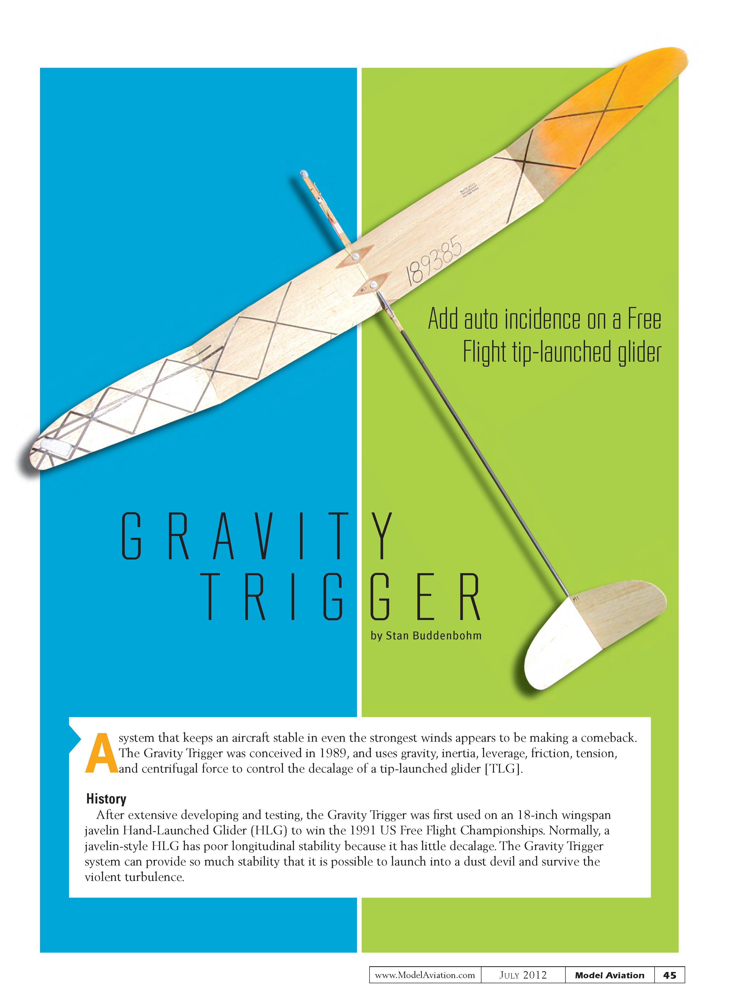
GRAVITY TRIGGER
by Stan Buddenbohm
A system that keeps an aircraft stable in even the strongest winds appears to be making a comeback. The Gravity Trigger was conceived in 1989 and uses gravity, inertia, leverage, friction, tension, and centrifugal force to control the decalage of a tip-launched glider (TLG).
History
After extensive development and testing, the Gravity Trigger was first used on an 18-inch wingspan javelin hand-launched glider (HLG) to win the 1991 US Free Flight Championships. Normally, a javelin-style HLG has poor longitudinal stability because it has little decalage. The Gravity Trigger system can provide so much stability that it is possible to launch into a dust devil and survive the violent turbulence.
The next time it was used was to latch and release my folding-wingtip HLG. I launched my 19-inch wingspan model, which opened to a 36-inch wingspan at transition. It worked beautifully and won a few times, but I dropped the idea for many years.
The system was used again, with a folding-wingtip model, to take second place at the Nationals the year that Bruce Kimbal introduced us to TLG by winning!
The Gravity Trigger was tucked away until Ralph Ray helped develop it for the 2011 Nats, where he won the TLG competition.
The Nuts and Bolts
The Gravity Trigger system holds the tailboom in the launch decalage position until the moment of transition. At that time, the Gravity Trigger uses the model’s change in speed and angle to release the tailboom into the decalage for glide. It requires no timer. This model also incorporates Ken Bauer’s superb radio dethermalizer unit installed inside the nose of the glider.
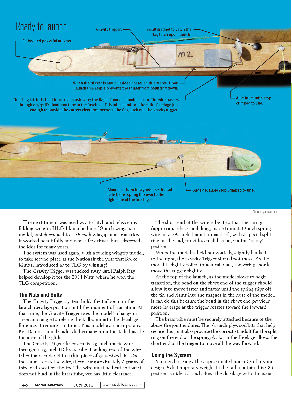
The Gravity Trigger lever arm is 1/32-inch music wire running through a 1/32-inch I.D. brass tube. The long end of the wire is bent and soldered to a thin piece of galvanized tin. On that same side, approximately 2 grams of thin lead sheet are attached to the tin to provide weight. The wire must be bent so that it does not bind in the brass tube, yet has very little clearance.
The short end of the wire is bent so that the spring (approximately 0.7 inches long, made from 0.009-inch spring wire on a 0.09-inch diameter mandrel), with a special split ring on the end, provides small leverage in the "ready" position.
When the model is held horizontally, slightly banked to the right, the Gravity Trigger should not move. As the model is rolled toward neutral bank, the spring should move the trigger slightly.
At the top of the launch, as the model slows to begin transition, the bend on the short end of the trigger should allow it to move faster and faster until the spring slips off the tin and slams into the magnet in the nose of the model. It can do this because the bend in the short end provides more leverage as the trigger rotates toward the forward position.
The brass tube must be securely attached because of the abuse the joint endures. The 1/32-inch plywood bits that help secure this joint also provide the correct standoff for the split ring on the end of the spring. A slot in the fuselage allows the short end of the trigger to move all the way forward.
Using the System
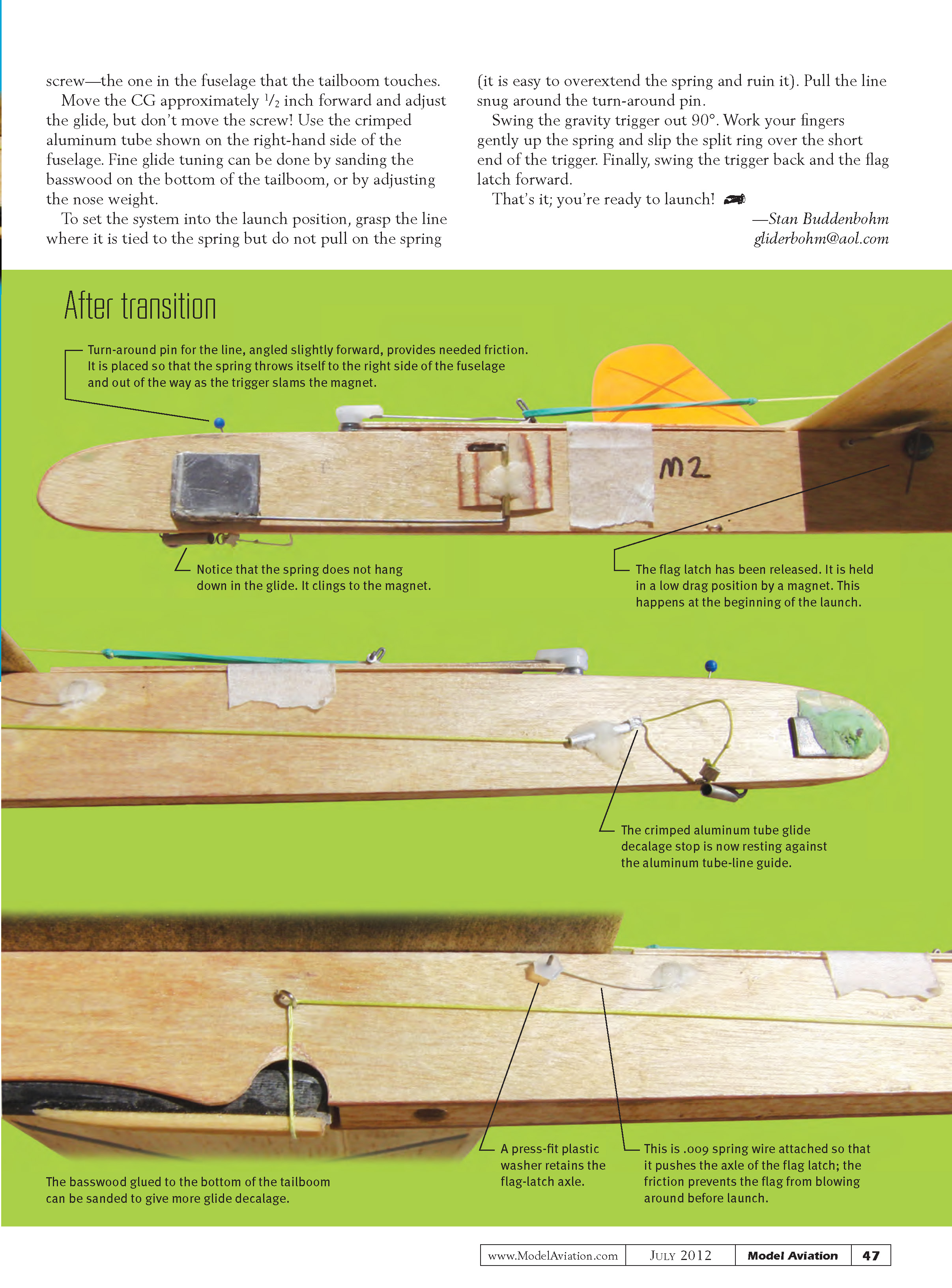
You need to know the approximate launch center of gravity (CG) for your design. Add temporary weight to the tail to attain this CG position. Glide test and adjust the decalage with the usual screw—the one in the fuselage that the tailboom touches. Move the CG approximately 1/2 inch forward and adjust the glide, but don’t move the screw. Use the crimped aluminum tube on the right-hand side of the fuselage. Fine glide tuning can be done by sanding the basswood on the bottom of the tailboom or by adjusting the nose weight.
To set the system into the launch position:
- Grasp the line where it is tied to the spring, but do not pull on the spring (it is easy to overextend the spring and ruin it).
- Pull the line snug around the turn-around pin.
- Swing the gravity trigger out 90°.
- Work your fingers gently up the spring and slip the split ring over the short end of the trigger.
- Finally, swing the trigger back and the flag latch forward.
That's it.
— Stan Buddenbohm
Transcribed from original scans by AI. Minor OCR errors may remain.

