
Great Planes P-51 Mustang GP/EP ARF
If it's possible for an aircraft to be considered iconic, the North American P-51 Mustang would surely be at or near the top of the list. Entering service in World War II, the drop-tank-equipped aircraft were the first fighters with the range to escort Allied bombers to Germany and back.
Armed with six .50-caliber Browning M2 machine guns, the P-51s and their crews decimated Luftwaffe airplanes and pilots. The propeller-driven Mustangs were even used to shoot down V-1 buzz bombs and scored aerial victories over jet-engine-equipped Messerschmitt Me 262s on their way to Allied air superiority over Europe.
In 1944, the Truman Committee (formerly known as the Senate Special Committee to Investigate the National Defense Program) rated the Mustang as "the most aerodynamically perfect pursuit plane in existence."
With its sleek looks and rich history, it's no wonder the Mustang has become a "must-have" for nearly anyone who aspires to fly RC. This aircraft is so popular that hardly a month goes by without someone showing up at my club's field wanting to fly a P-51 as his or her first model.
The Great Planes P-51 Mustang Sport Fighter, released as part of the Sport Fighter Series, won't fulfill the role of a primary trainer, but it should allow aspiring warbird pilots to move up to their favorite fighters sooner rather than later.
The Great Planes P-51 is a Sport Scale model that is designed to fly with a simple four-channel radio system, standard servos, and the choice of an electric or glow power system. In keeping with the simple requirements of a sport airplane, Great Planes omitted the flaps and equipped the Mustang with fixed landing gear.
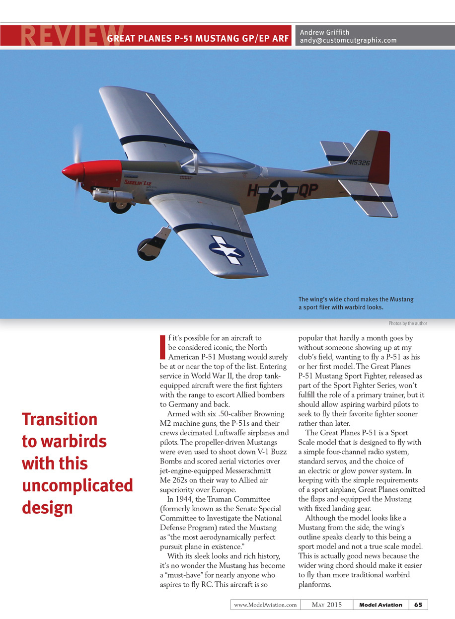
Although the model looks like a Mustang from the side, the wing's outline speaks clearly to this being a sport model and not a true scale model. This is actually good news because the wider wing chord should make it easier to fly than more traditional warbird planforms.
As a model aircraft reviewer, I am often assigned projects that include a power system. I occasionally get to choose my preferred power system, but the P-51 Mustang I was provided included both an electric and a glow power system to evaluate. The aircraft arrived with a full electric setup, an extra servo for the throttle, a receiver battery, and an O.S. glow-powered engine.
Construction for Both Versions
The first thing I did was examine the 28-page instruction manual. Similar to most products sold by Great Planes, the booklet is well written with clear illustrations and plenty of photographs. It covers power-system installation, as well as a complete inventory, safety instructions, and center-of-gravity (CG) location. Even relevant portions of the AMA Safety Code are included.
A paper addendum explains the canopy installation for glow motors and a generic insert shows the proper way to shrink and seal the covering on an ARF model.
Because I would be flying the Mustang with both glow and electric power, it made sense to proceed with the electric installation first. The cowl had to be cut out to clear the muffler for the O.S. engine later.
The Mustang will be assembled using Zap thin and medium CA glue and Pacer Z-Poxy 15- and 30-minute epoxy. All are available from Frank Tiano Enterprises.
Assembly starts with the wings.
After approximately 15 minutes with a sock-covered covering iron, all of the wrinkles and sags were gone and the Mustang looked sharp. All of the control surfaces were factory-hinged using CA hinges, and each was given a tug to ensure everything was properly glued.
Pull strings are provided to pull the aileron servo wires through the wing and the servos are mounted using the hardware provided with the servos. All of the servo mounting holes are threaded then hardened with thin Zap CA. After the wires are fished through, tape them to the top of the wings so they don't fall back into the holes.
An alignment pin is glued into the right wing near the trailing edge. Use 80-grit sandpaper and scuff the gluing area of the alignment pin.
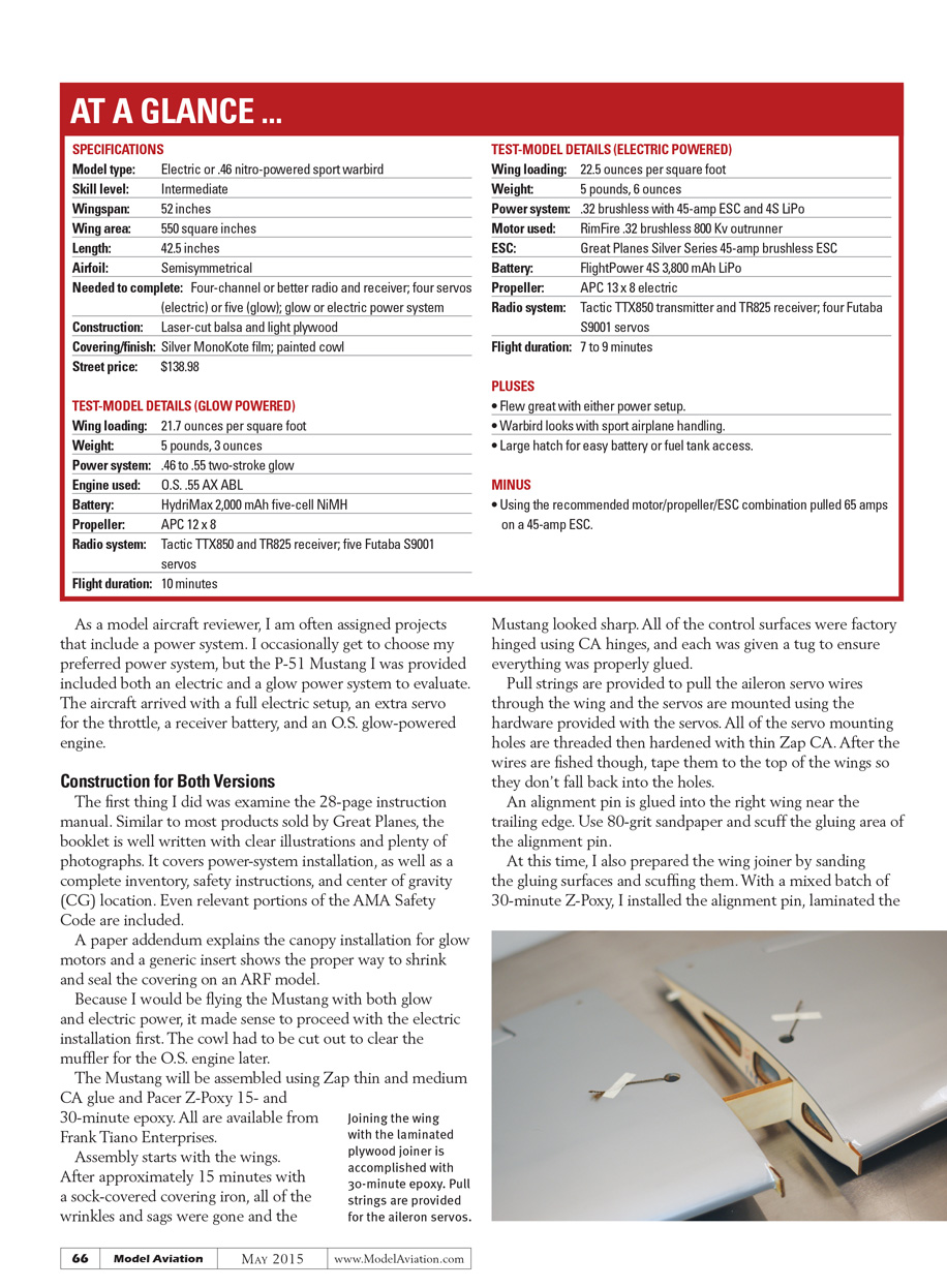
At this time, I also prepared the wing joiner by sanding the gluing surfaces and scuffing them. With a mixed batch of 30-minute Z-Poxy, I installed the alignment pin, laminated the wing joiner together, and clamped it off to dry. Make sure you clean up excess epoxy on the wing joiner or you will have to sand it off later to get it to properly fit.
Scuff the gluing area of the wing joiner and use 30-minute epoxy to glue the joiner, alignment pin, and root ribs to join the wing. When you have all of the epoxy cleaned up with alcohol, tape the entire assembly together with low-tack painter's tape and set it aside to dry.
When the glue is dry, you can install a Y-harness on the aileron leads and mount the aileron pushrods and control horns. All of the control linkages use an L-bend on the servo end with a small nylon keeper and a nylon clevis on the control-surface end for final adjustment. The control horns for the ailerons mount with small self-tapping screws so there are no unsightly backplates on the top of the control surface.
As with the servo screws, install the screw, remove it, and harden the threads with thin CA. This is a perfect time to use thin CA tips to get a small drop of CA directly in the hole instead of making a mess.
The wing fairing and the distinctive Mustang radiator scoop are installed directly on the bottom of the wing. If you remove the covering with a hobby knife, you should first replace the blade or do what I do: use an old soldering-iron point, which will melt the covering and seal the edge without any danger of cutting into and weakening the wood. The parts were attached with RC-56 canopy glue and taped down to dry.
The landing gear is installed next.
There are flat spots on the landing gear for the wheel collar setscrews, which saves time. The only thing I did that wasn’t mentioned in the manual was mark my drill at 10 mm from the tip with painter’s tape before drilling holes for the landing gear straps. This acts as a depth gauge to show you where to stop drilling to avoid accidentally cutting through the wing. The landing gear extends forward of the leading edge when installed, which should make ground handling tame.
All of the tail surfaces are prehinged with CA hinges, but unlike the ailerons, the control horns use nylon backplates. I suspect this is because of the thin control surfaces.
The covering was removed from the gluing areas with a soldering iron. Many models I have built required sanding the elevator saddle and occasionally shimming to get the stabilizer level with the wing, but the P-51 Mustang lined up perfectly.
Z-Poxy 30-minute formula was used to attach the stabilizer and vertical fin and everything was taped in place while it dried. The tail wheel is under the rudder instead of its scale location behind the radiator, but similar to the forward-raked main landing gear, its more rearward location will contribute to better ground handling.
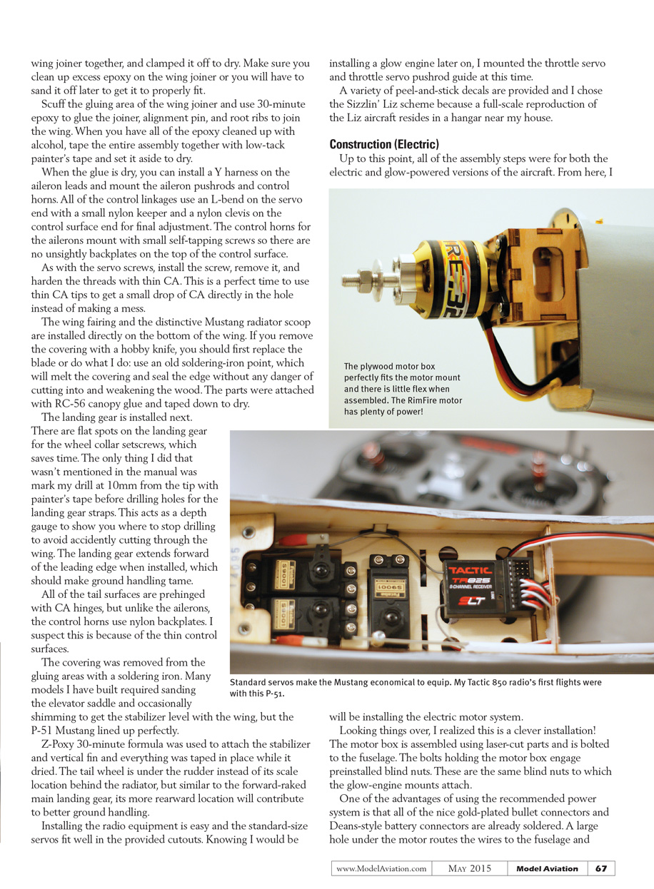
Installing the radio equipment is easy and the standard-size servos fit well in the provided cutouts. Knowing I would be installing a glow engine later on, I mounted the throttle servo and throttle servo pushrod guide at this time.
A variety of peel-and-stick decals are provided and I chose the Sizzlin’ Liz scheme because a full-scale reproduction of the Liz aircraft resides in a hangar near my house.
Construction (Electric)
Up to this point, all of the assembly steps were for both the electric and glow-powered versions of the aircraft. From here, I will be installing the electric motor system.
Looking things over, I realized this is a clever installation! The motor box is assembled using laser-cut parts and is bolted to the fuselage. The bolts holding the motor box engage preinstalled blind nuts. These are the same blind nuts to which the glow-engine mounts attach.
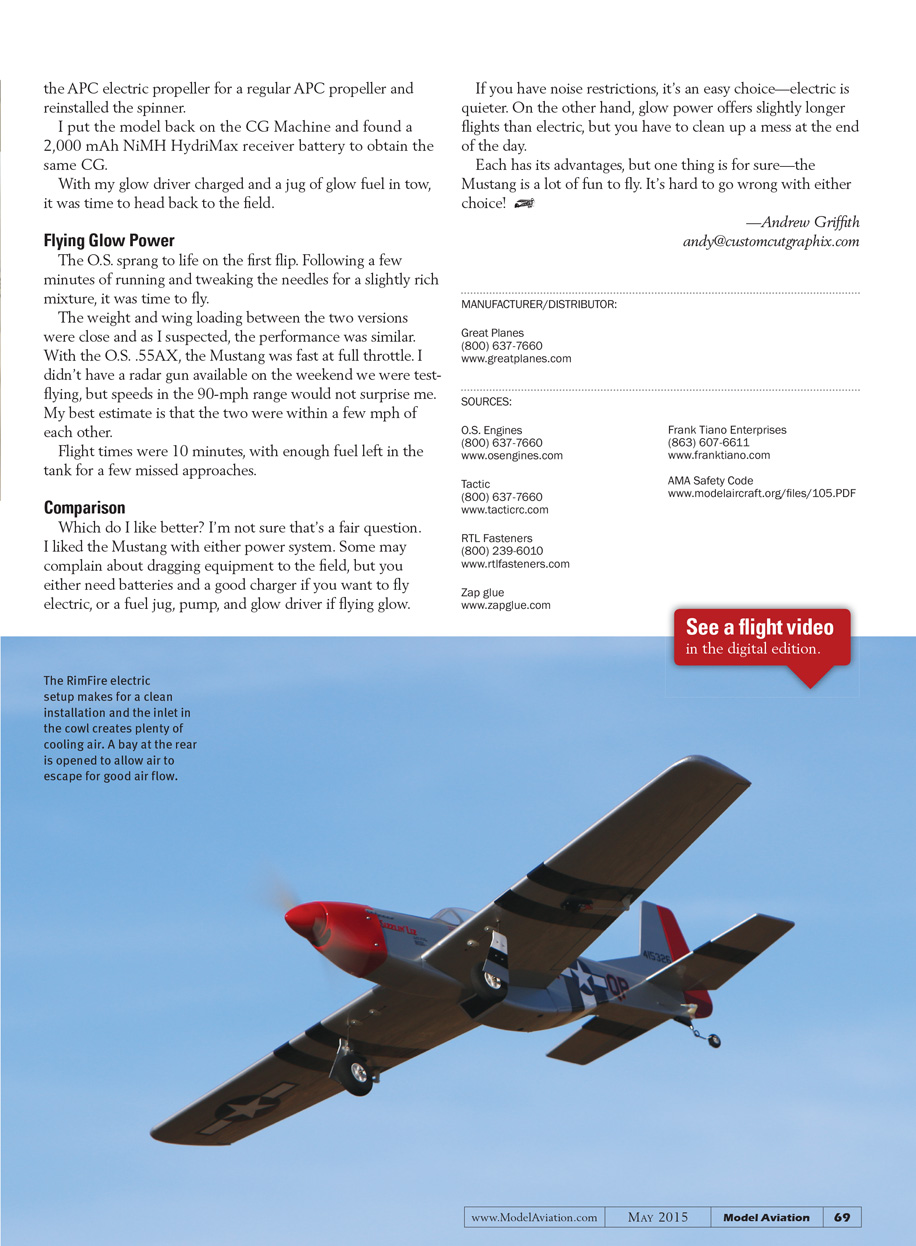
One of the advantages of using the recommended power system is that all of the nice gold-plated bullet connectors and Deans-style battery connectors are already soldered. A large hole under the motor routes the wires to the fuselage and provides airflow over the components. If using electric power, open a few of the holes on the bottom of the fuselage at the rear, as shown in the manual, to allow for exit air.
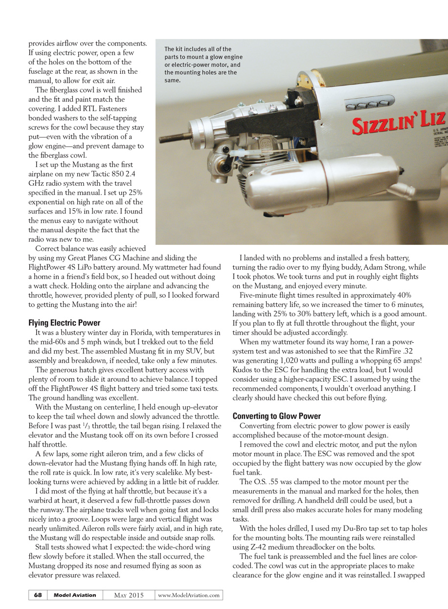
The fiberglass cowl is well finished and the fit and paint match the covering. I added RTL Fasteners bonded washers to the self-tapping screws for the cowl because they stay put—even with the vibration of a glow engine—and prevent damage to the fiberglass cowl.
I set up the Mustang as the first airplane on my new Tactic 850 2.4 GHz radio system with the travel specified in the manual. I set up 25% exponential on high rate on all of the surfaces and 15% in low rate. I found the menus easy to navigate without the manual despite the fact that the radio was new to me.
Correct balance was easily achieved by using my Great Planes CG Machine and sliding the FlightPower 4S LiPo battery around. My wattmeter had found a home in a friend’s field box, so I headed out without doing a watt check. Holding onto the airplane and advancing the throttle, however, provided plenty of pull, so I looked forward to getting the Mustang into the air!
Flying Electric Power
It was a blustery winter day in Florida, with temperatures in the mid-60s and 5 mph winds, but I trekked out to the field and did my best. The assembled Mustang fit in my SUV, but assembly and breakdown, if needed, take only a few minutes.
The generous hatch gives excellent battery access with plenty of room to slide it around to achieve balance. I topped off the FlightPower 4S flight battery and tried some taxi tests. The ground handling was excellent.
With the Mustang on centerline, I held enough up-elevator to keep the tail wheel down and slowly advanced the throttle. Before I was past one-third throttle, the tail began rising. I relaxed the elevator and the Mustang took off on its own before I crossed half throttle.
A few laps, some right aileron trim, and a few clicks of down-elevator had the Mustang flying hands-off. In high rate, the roll rate is quick. In low rate, it’s very scale-like. My best-looking turns were achieved by adding in a little bit of rudder.
I did most of the flying at half throttle, but because it’s a warbird at heart, it deserved a few full-throttle passes down the runway. The airplane tracks well when going fast and locks nicely into a groove. Loops were large and vertical flight was nearly unlimited. Aileron rolls were fairly axial, and in high rate, the Mustang will do respectable inside and outside snap rolls.
Stall tests showed what I expected: the wide-chord wing flew slowly before it stalled. When the stall occurred, the Mustang dropped its nose and resumed flying as soon as elevator pressure was relaxed.
I landed with no problems and installed a fresh battery, turning the radio over to my flying buddy, Adam Strong, while I took photos. We took turns and put in roughly eight flights on the Mustang, and enjoyed every minute.
Five-minute flight times resulted in approximately 40% remaining battery life, so we increased the timer to 6 minutes, landing with 25% to 30% battery left, which is a good amount. If you plan to fly at full throttle throughout the flight, your timer should be adjusted accordingly.
When my wattmeter found its way home, I ran a power-system test and was astonished to see that the RimFire .32 was generating 1,020 watts and pulling a whopping 65 amps! Kudos to the ESC for handling the extra load, but I would consider using a higher-capacity ESC. I assumed that by using the recommended components I wouldn't overload anything. I clearly should have checked this out before flying.
Converting to Glow Power
Converting from electric power to glow power is easily accomplished because of the motor-mount design.
I removed the cowl and electric motor, and put the nylon motor mount in place. The ESC was removed and the spot occupied by the flight battery was now occupied by the glow fuel tank.
The O.S. .55 was clamped to the motor mount per the measurements in the manual and marked for the holes, then removed for drilling. A handheld drill could be used, but a small drill press also makes accurate holes for many modeling tasks.
With the holes drilled, I used my Du-Bro tap set to tap holes for the mounting bolts. The mounting rails were reinstalled using Z-42 medium threadlocker on the bolts.
The fuel tank is preassembled and the fuel lines are color-coded. The cowl was cut in the appropriate places to make clearance for the glow engine and it was reinstalled. I swapped the APC electric propeller for a regular APC propeller and reinstalled the spinner.
I put the model back on the CG Machine and found a 2,000 mAh NiMH HydriMax receiver battery to obtain the same CG.
With my glow driver charged and a jug of glow fuel in tow, it was time to head back to the field.
Flying Glow Power
The O.S. sprang to life on the first flip. Following a few minutes of running and tweaking the needles for a slightly rich mixture, it was time to fly.
The weight and wing loading between the two versions were close and as I suspected, the performance was similar. With the O.S. .55AX, the Mustang was fast at full throttle. I didn't have a radar gun available on the weekend we were test-flying, but speeds in the 90-mph range would not surprise me. My best estimate is that the two were within a few mph of each other.
Flight times were about 10 minutes, with enough fuel left in the tank for a few missed approaches.
Comparison
Which do I like better? I'm not sure that's a fair question. I liked the Mustang with either power system. Some may complain about dragging equipment to the field, but you either need batteries and a good charger if you want to fly electric, or a fuel jug, pump, and glow driver if flying glow.
If you have noise restrictions, it's an easy choice—electric is quieter. On the other hand, glow power offers slightly longer flights than electric, but you have to clean up a mess at the end of the day.
Each has its advantages, but one thing is for sure—the Mustang is a lot of fun to fly. It's hard to go wrong with either choice!
—Andrew Griffith [email protected]
Manufacturer / Distributor
- Great Planes
(800) 637-7660 www.greatplanes.com
Sources
- O.S. Engines
(800) 637-7660 www.osengines.com
- Tactic
(800) 637-7660 www.tacticrc.com
- RTL Fasteners
(800) 239-6010 www.rtlfasteners.com
- Zap glue
- Frank Tiano Enterprises
(863) 607-6611 www.franktiano.com
- AMA Safety Code
www.modelaircraft.org/files/105.PDF
Transcribed from original scans by AI. Minor OCR errors may remain.

