
Great Planes WACO YMF 5D
Tom Sullivan
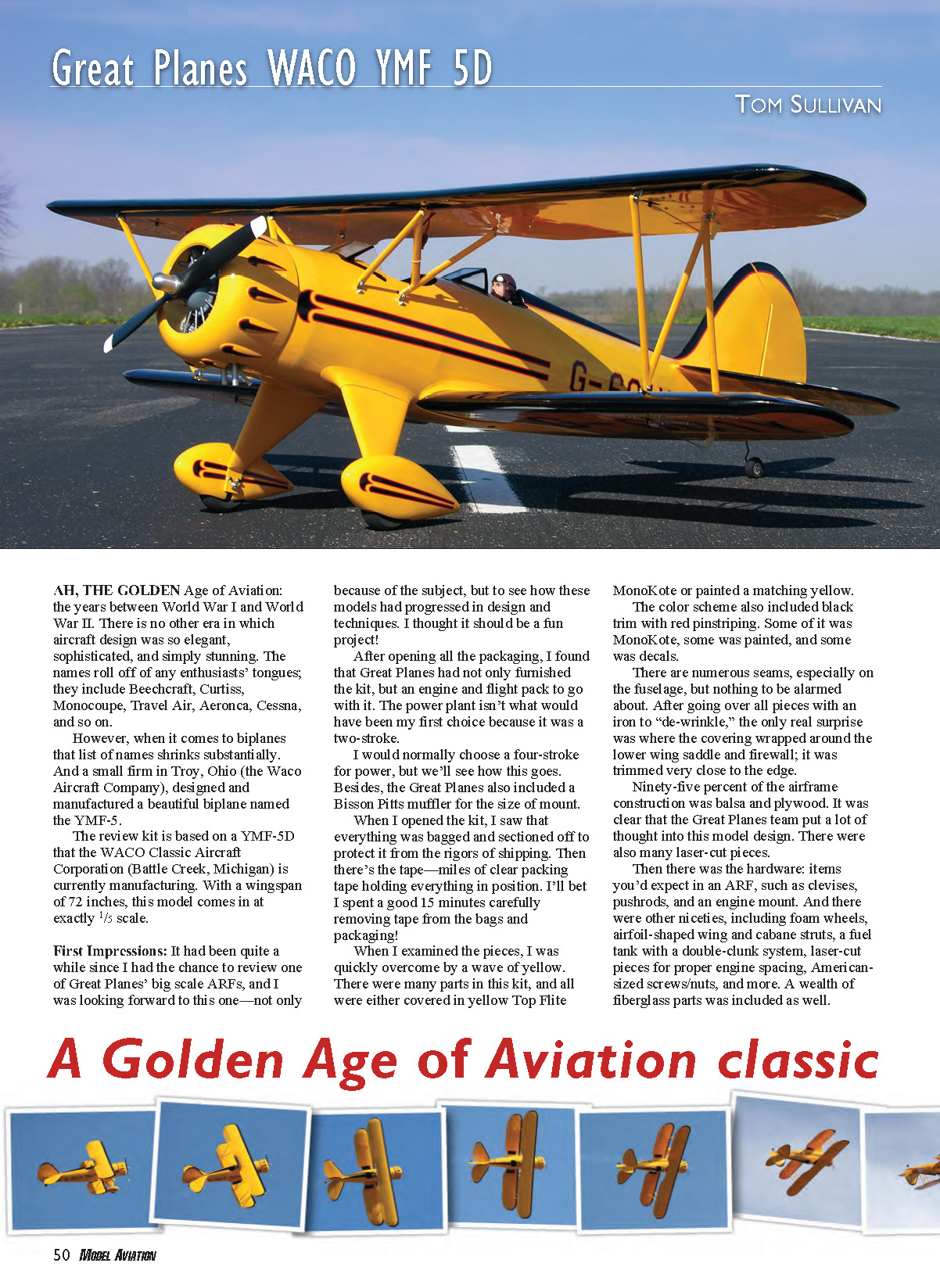
AH, the golden age of aviation: the years between World War I and World War II. There is no other era in which aircraft design was so elegant, sophisticated, and simply stunning. The names roll off any enthusiast’s tongue: Beechcraft, Curtiss, Monocoupe, Travel Air, Aeronca, Cessna, and so on.
When it comes to biplanes that list of names shrinks substantially. A small firm in Troy, Ohio (the Waco Aircraft Company) designed and manufactured a beautiful biplane named the YMF-5. The review kit is based on a YMF-5D that WACO Classic Aircraft Corporation (Battle Creek, Michigan) is currently manufacturing. With a wingspan of 72 inches, this model comes in at exactly 1/5 scale.
First impressions: it had been quite a while since I reviewed one of Great Planes’ big scale ARFs, and I was looking forward to this one—not only because of the subject, but to see how these models had progressed in design and techniques. I thought it should be a fun project!
After opening all the packaging, I found that Great Planes had not only furnished the kit but also an engine and flight pack. The power plant supplied was a two-stroke; I would normally choose a four-stroke for power, but we’ll see how this goes. Great Planes also included a Bisson Pitts muffler for the size of mount.
Everything was bagged and sectioned to protect it during shipping. There was a lot of clear packing tape holding everything in position; I spent a good 15 minutes carefully removing tape from the bags and packaging.
When I examined the pieces, I was quickly overcome by a wave of yellow. Many parts in this kit were either covered in yellow Top Flite MonoKote or painted a matching yellow. The color scheme also included black trim with red pinstriping. Some of it was MonoKote, some painted, and some were decals.
There are numerous seams, especially on the fuselage, but nothing to be alarmed about. After going over all pieces with an iron to “de-wrinkle” the covering, the only real surprise was where the covering wrapped around the lower wing saddle and firewall; it was trimmed very close to the edge.
Ninety-five percent of the airframe construction is balsa and plywood. It was clear the Great Planes team put a lot of thought into this model design. There were many laser-cut pieces.
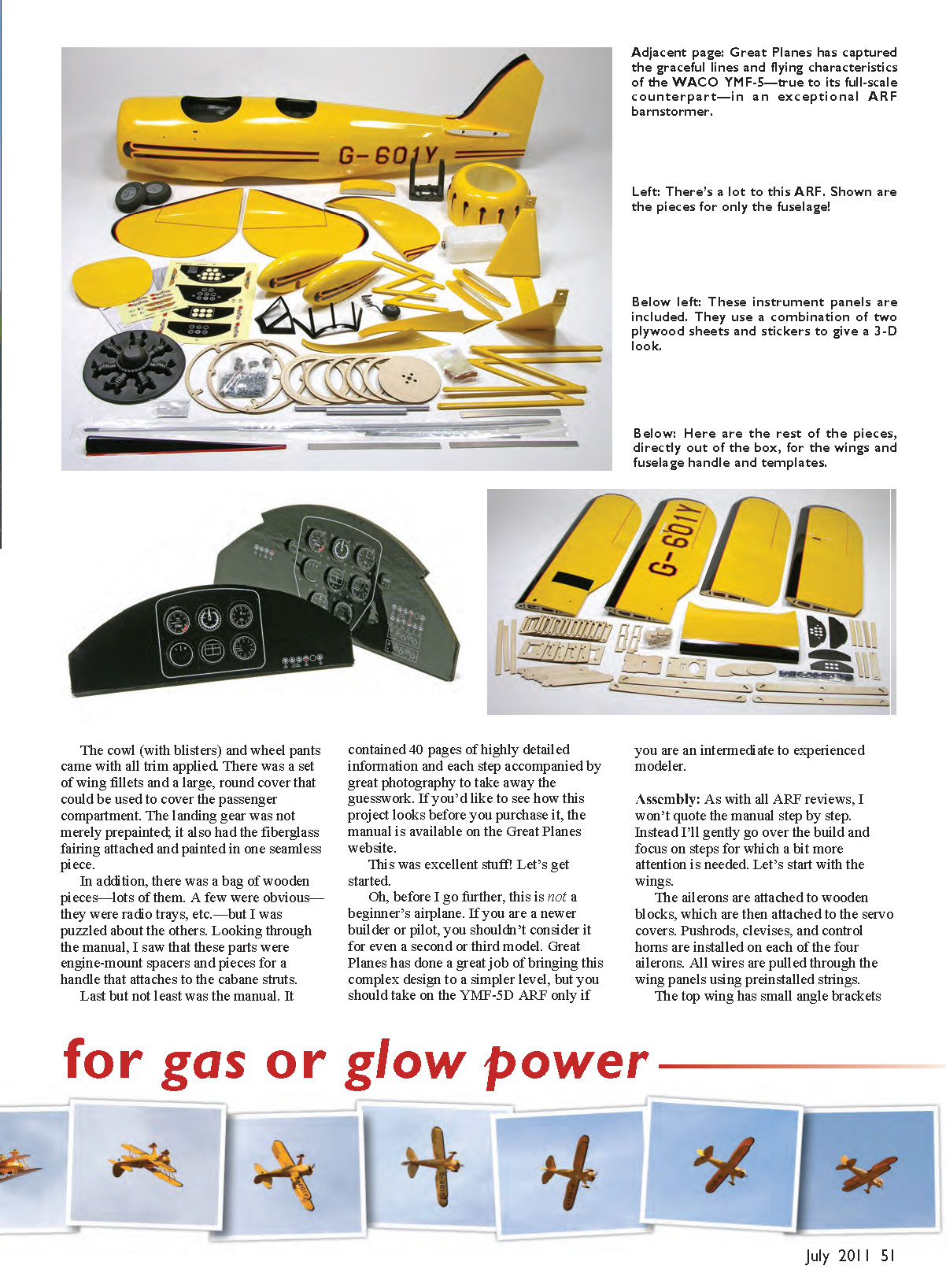
The kit hardware is what you’d expect in an ARF—clevises, pushrods, and an engine mount—and a few niceties: foam wheels, airfoil-shaped wing and cabane struts, a fuel tank with a double-clunk system, laser-cut pieces for proper engine spacing, American-sized screws/nuts, and more. A wealth of fiberglass parts were included: the cowl (with blisters) and wheel pants came with all trim applied. There was a set of wing fillets and a large, round cover that could be used to cover the passenger compartment. The landing gear was not merely prepainted; it also had the fiberglass fairing attached and painted in one seamless piece.
There was also a bag of wooden pieces—lots of them. A few were obvious—radio trays, etc.—but others were puzzling until I checked the manual: they were engine-mount spacers and pieces for a handle that attaches to the cabane struts.
Last but not least was the manual. It contained 40 pages of highly detailed information and each step was accompanied by excellent photography to take away the guesswork. If you'd like to see how the project looks before you purchase it, the manual is available on the Great Planes website.
This was excellent stuff. Let's get started.
Note: this is not a beginner's airplane. If you are a newer builder or pilot, you shouldn't consider it for even a second or third model. Great Planes has done a great job of simplifying this complex design, but you should take on the YMF-5D ARF only if you are an intermediate to experienced modeler.
Assembly
As with all ARF reviews, I won't quote the manual step by step. Instead I'll go over the build and focus on steps that need a bit more attention. Let's start with the wings.
The ailerons are attached to wooden blocks, which are then attached to the servo covers. Pushrods, clevises, and control horns are installed on each of the four ailerons. All wires are pulled through the wing panels using preinstalled strings.
The wing panels are assembled and then glued together (two panels for the bottom wing and three for the top). Each panel has a set of dihedral braces that you need to build.
The leading-edge (LE) braces have two light-plywood parts sandwiching an aluminum center brace. Together they make an incredibly strong piece. The rear braces are light-plywood pieces glued together. Before mixing the epoxy to assemble each wing, take extra time to file and sand the braces so they fit. Originally they wouldn't push into the wing slots at all, and it took a lot of elbow grease to shape them so they would slide in snugly.
Assembly then moves to the fuselage. The landing gear installation is extremely straightforward because of the factory work. There is a built-up cover that is glued into place after the landing gear is attached. This cover had two small balsa pieces taped to the bottom; they appeared to be padding for shipping—be sure to remove them first. The manual doesn't mention this.
You will have to trim 1/4 inch off each main gear axle; that's easy to do with a rotary tool and cutoff wheel.
Those extra wood pieces I mentioned earlier become useful here: a few steps double up the laser-cut plywood parts and they form a sturdy handle that mounts to the cabane struts. This handle is perfect for securely holding and moving the fuselage with one hand. Even after the radio and engine are installed, the handle sits directly on the CG and works well when you have to flip the fuselage upside-down—it makes a nice, flat surface.
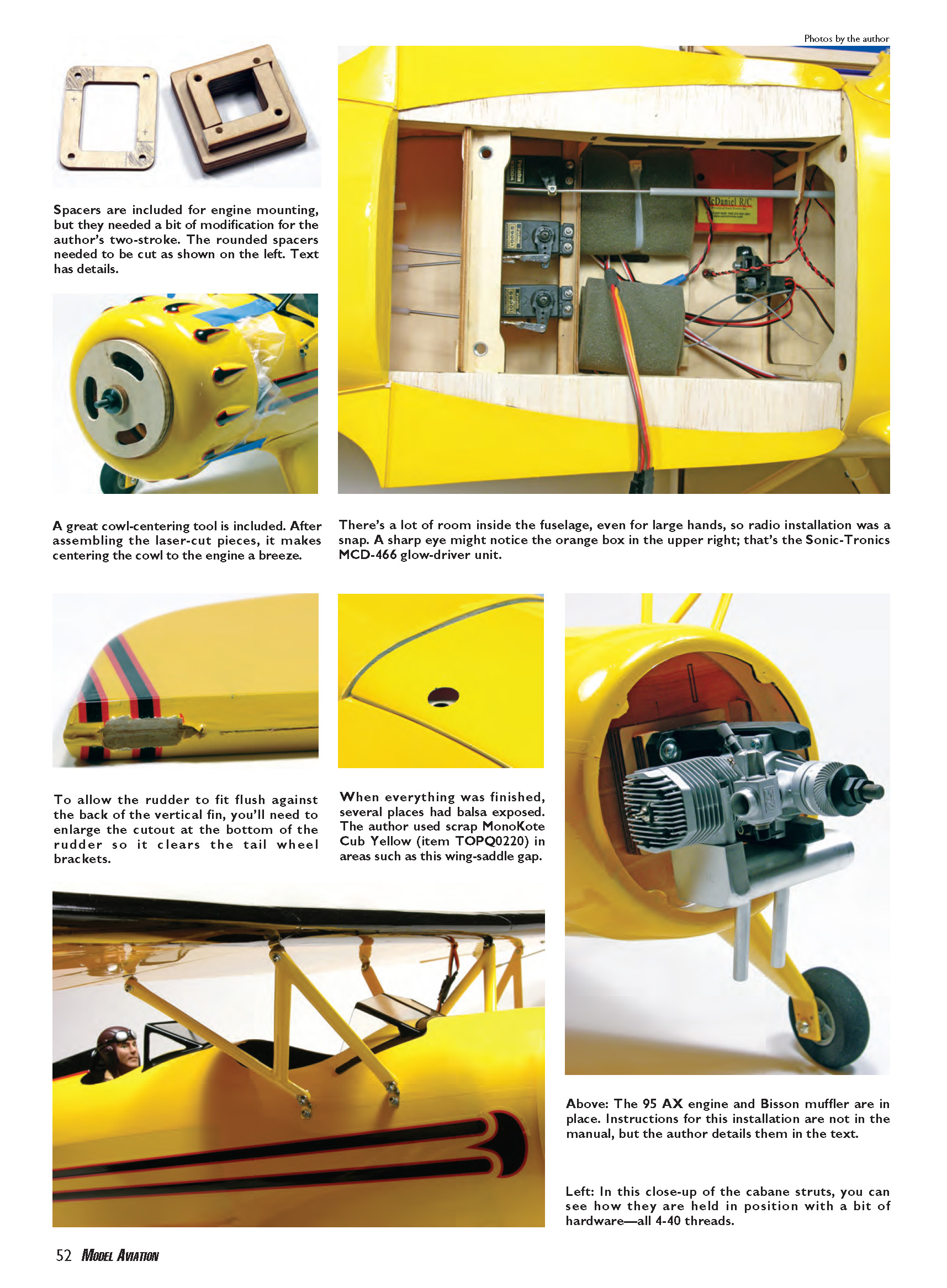
Tail assembly: stabilizer halves are installed using a couple of aluminum tubes that slide into the fuselage and align everything nicely. Then install the tail wheel. Note that you will have to enlarge the cutout in the bottom of the rudder quite a bit to clear the tail wheel mounts. Once the cutout is correct, the rudder is attached using three CA-type hinges.
Rudder and elevator servos, pushrods, clevises, and control horns are installed next. There are no surprises here, and all included hardware works well.
Engine installation: the manual covers installation of a four-stroke glow and a two-stroke gasoline power plant in detail. However, the O.S. 95 AX two-stroke glow engine supplied with the review model isn't covered specifically.
To install the O.S. 95 AX, follow the four-stroke instructions for the first three steps. The fourth step (wood engine spacers) is where things change. Mount the O.S. to the mount. Although it needs to be installed far forward, the engine mount has a sharply angled portion at the front of each mounting beam—do not use this area because the mount thins significantly. I mounted the engine approximately 1/8 inch aft of this angle.
There was not enough of either wooden mount spacers to get the correct firewall-to-drive washer distance of 6 11/16 inches. I combined the spacers: the rounded spacers had to be cut so the mounting holes lined up. When finished I used all six square spacers and an additional four modified rounded spacers. Your measurements might be different, but heed the 6 11/16 inches; that is the minimum distance. A little longer is okay, but do not shorten this distance. Also be sure the muffler you use will clear the firewall—the supplied Bisson Pitts fit perfectly.
Once you have the proper distance, glue all the pieces together and fuel-proof them by using thinned 30-minute epoxy or spraying on a coat of clear fuelproof paint. Then return to the manual at the eighth step of engine installation and finish bolting the mount to the model, hooking up the throttle linkage and installing the throttle servo.
If you go with the two-stroke option, the throttle pushrod will likely need to be drilled in a different location than shown in the manual.
If you choose to power the YMF-5D with a gas engine, the WACO package includes a few other laser-cut pieces to build an ignition and battery tray that mounts to the front of the firewall, directly above the engine. Also included is a different plastic pushrod to keep ignition noise away from the radio system. These are very nice touches.
Fuel tank: most ARFs include a fuel tank, but this is the first I’ve seen that also includes a double-clunk system. I’ve always preferred this system; it makes filling and emptying the tank easier. The tank is held in the fuselage with a rubber band. The manual shows how to install it using a hook, but that didn’t work for me. Luckily my wife’s hands were the right size to reach into the small space and put things right!
Cowl installation: assemble the pieces of the cowl-centering tool. I had to sand the cowl opening considerably to allow the ring to fit. Once I attained a good fit, I made the cutout for muffler clearance and engine cooling.
Mounting the cowl to the fuselage is designed to be discreet, with nothing visible from the outside (as on the full-scale WACO). Two laser-cut light-plywood rings are included: one bolts to the fuselage and the other is glued to the inside of the cowl. It is a challenge to get adhesive inside the cowl with the front opening completely covered by the centering tool. The manual advises brushing on 30-minute epoxy (with fiberglass filler) and shoving on the cowl, but that seemed messy, so I modified the centering tool by cutting out three large sections so I could carefully apply the epoxy with a long paintbrush. It worked well. The cowl doesn’t have to be epoxied all the way around—just enough to hold it so it can be carefully removed. Then you can get to the inside and do a proper job with the epoxy.
Radio system: installation is a breeze. A large wing-saddle opening allows even large hands to get to everything. Great Planes includes a variety of light-plywood templates to make easy work of cutting holes for the external switch and charging jack.
I didn’t want to cut a hole in the cowl through which to stick the glow-plug igniter. While looking at options I contacted Sonic-Tronics. The company has both a remote Ni-Starter, which moves the glow-plug connection to a different point (say the cockpit), and an onboard system, which Sonic-Tronics thought was the better choice. That system is normally used on four-stroke engines to keep the plug hot, but it also allows you to have onboard “heat” to start the engine with no external wires.
I used the Super Mcd466 onboard glow driver: a small, self-contained driver that has everything you need, including a charger. The little box works in parallel with the throttle servo (via a Y-harness) and has a rotary adjustment to determine the on/off point. I set the drive to be on at 0%–25% throttle and off above that. A great safety feature of the Mcd466 is that when you turn off the radio the power to the plug is off as well. I installed the indicator light in the floor of the front cockpit so I can easily see when the driver is powered during startup. I’m not sure how long its onboard battery will last, but I’ve made as many as eight flights in a day and it still had power.
Finishing assembly: the wheel pants are a breeze to install, and a number of other parts are adhered using RC-56 (or equivalent) white glue. You can detail the included dummy engine, make the model a one-seater by gluing on the included forward cockpit cover, or make instrument panels for both cockpits. I would have liked it if Great Planes had included a pilot, so I picked one up at my local hobby shop.
Bolting everything together for the first time took close to 10 minutes. The bottom wing attaches to the fuselage with two nylon bolts. The upper wing and struts attach with 4-40 screws, washers, and locknuts. Be sure to have extras on hand; they’re sure to disappear at the field.
All finished, the review YMF-5D came in at 12.5 pounds ready to fly—slightly less than the manual’s cited weight, which is good. Surprisingly, the CG was spot on; I was expecting to have to move things slightly forward.
Flying
Before taking the WACO to the field I watched Great Planes' online videos—specifically noting the speed at which the models were flying. It worried me that the flying looked a tad faster than scale, so for the first flight I kept speed up a bit until I was comfortable.
While throttling up on the takeoff roll it became apparent this aircraft was overpowered. After a 40–50 foot roll, it climbed resembling a pylon racer rather than a barnstormer. After a few trim passes and photo runs, I wrung out the model at full throttle—there was a lot of power and the airframe handled it well. Huge loops, Cuban eights, and Immelmanns were in the YMF-5's repertoire at this power level. There wasn't enough power to hover, but you could practice most novice and advanced RC aerobatic maneuvers with this setup.
First landing: throttling down, the WACO came in a little hot and completely overshot the runway. Even with all that extra drag the model was a floater and didn't slow as quickly as I thought. After a few attempts I found throttling to idle immediately after turning onto downwind made the base and final legs much more manageable.
Trimmed for scale flight (one-third to half throttle with the O.S. 95 AX), the model flew slowly and gracefully. I used half throttle for rolls and loops; at that setting the model would do anything the full-scale aircraft might do, and do it well.
Takeoffs need a lot of right rudder to keep the aircraft pointed down the runway. Landings are a bit bouncy using the included foam wheels; I’ll probably switch to a softer foam or rubber.
The Sonic-Tronics onboard glow system has been a great addition and makes starting the 95 AX a breeze.
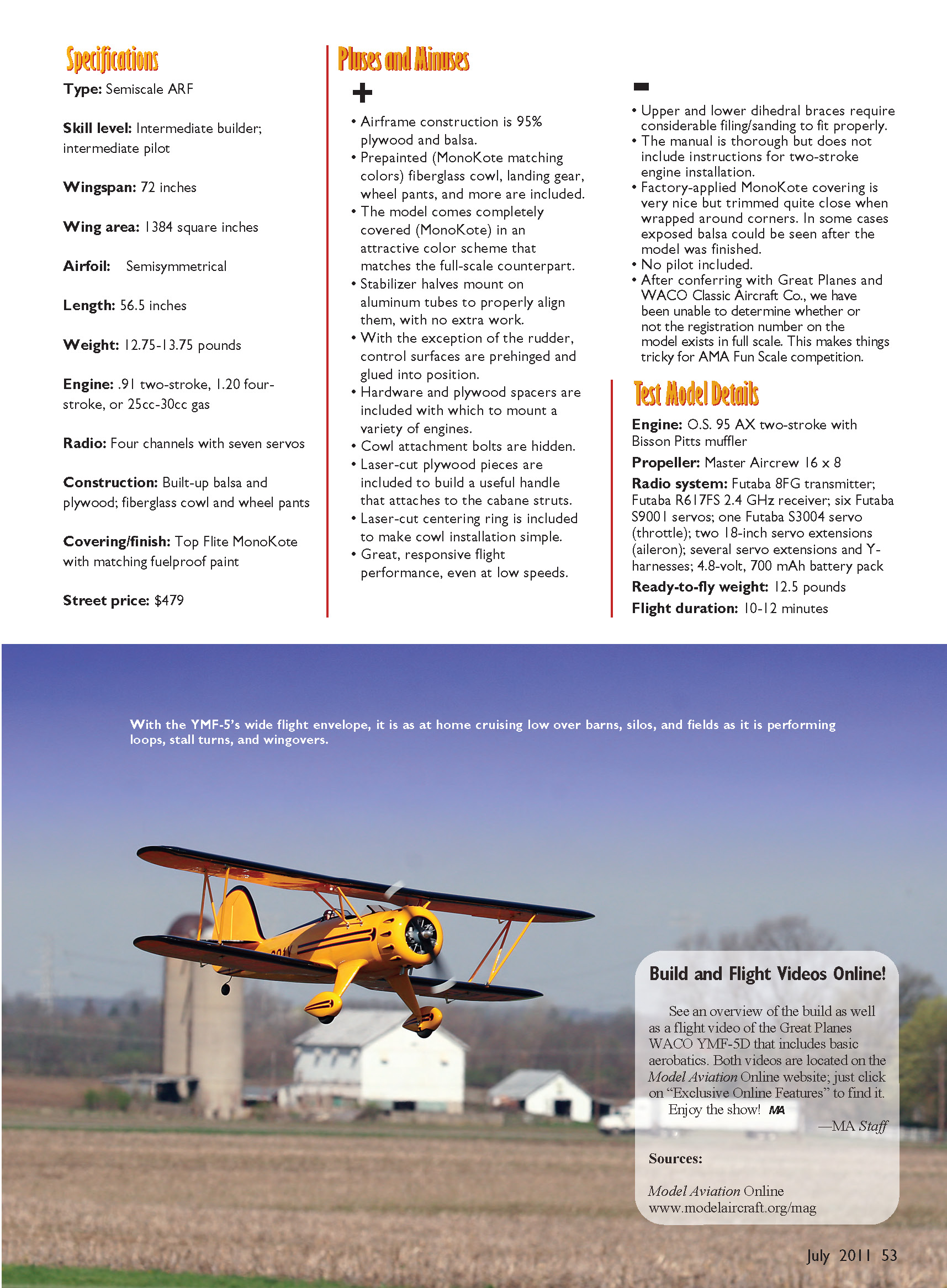
Since the first flights I’ve piloted this ARF many times and am having a ball with it. It's a true barnstormer, and Great Planes has done a fine job with the design. Experimenting with the flight envelope, I found that when the model is trimmed for scale flight (one-third to half throttle), going to full throttle causes it to climb rapidly; you and your elevator trim will become fast friends. On the low end this airplane has no tendency to tip stall or do anything alarming.
Although this YMF-5D is a great candidate for AMA Fun Scale competition, the fact that it comes with registration numbers that couldn't be found on any full-scale WACO presents a problem. After a bit of research I found a photo that should do the trick; it’s available online (see Sources).
Tom Sullivan [email protected]
Specifications
- Type: Semiscale ARF
- Skill level: Intermediate builder; intermediate pilot
- Wingspan: 72 inches
- Wing area: 1,384 square inches
- Airfoil: Semisymmetrical
- Length: 56.5 inches
- Weight: 12.75–13.75 pounds (manual); test model ready-to-fly: 12.5 pounds
- Engine: .91 two-stroke, 1.20 four-stroke, or 25cc–30cc gas
- Radio: Four channels with seven servos
- Construction: Built-up balsa and plywood; fiberglass cowl and wheel pants
- Covering/finish: Top Flite MonoKote with matching fuelproof paint
- Street price: $479
Pluses and Minuses
Pluses
- Airframe construction is 95% plywood and balsa.
- Prepainted (MonoKote matching colors) fiberglass cowl, landing gear, wheel pants, and more are included.
- Model comes completely covered (MonoKote) in an attractive color scheme that matches the full-scale counterpart.
- Stabilizer halves mount on aluminum tubes to properly align them, with no extra work.
- With the exception of the rudder, control surfaces are prehinged and glued into position.
- Hardware and plywood spacers are included to mount a variety of engines.
- Cowl attachment bolts are hidden.
- Laser-cut plywood pieces are included to build a useful handle that attaches to the cabane struts.
- Laser-cut centering ring is included to make cowl installation simple.
- Great, responsive flight performance, even at low speeds.
Minuses
- Upper and lower dihedral braces require considerable filing/sanding to fit properly.
- The manual is thorough but does not include instructions for two-stroke glow engine installation (as supplied in the review kit).
- Factory-applied MonoKote covering is very nice but trimmed quite close when wrapped around corners; in some cases exposed balsa could be seen after finishing.
- No pilot included.
- The registration number on the model could not be found on any full-scale WACO, which complicates AMA Fun Scale competition.
Test Model Details
- Engine: O.S. 95 AX two-stroke with Bisson Pitts muffler
- Propeller: Master Airscrew 16 x 8
- Radio system: Futaba 8FG transmitter; Futaba R617FS 2.4 GHz receiver; six Futaba S9001 servos; one Futaba S3004 servo (throttle); two 18-inch servo extensions (aileron); several servo extensions and Y-harnesses; 4.8-volt, 700 mAh battery pack
- Ready-to-fly weight: 12.5 pounds
- Flight duration: 10–12 minutes
Manufacturer / Distributor
Great Planes Model Manufacturing Box 9021 Champaign, IL 61826 (217) 398-8970 www.greatplanes.com
Sources
- Sonic-Tronics
(888) 721-0128 www.sonictronics.com
- 1-inch A-style propeller hub: Tru-Turn
(218) 479-9600 www.tru-turn.com
- Master Airscrew
- WACO photo (courtesy WACO Classic Aircraft Corporation):
Transcribed from original scans by AI. Minor OCR errors may remain.

