
From the Ground Up - Advanced RC Systems - 2004/02
This is my 10th installment in this initial phase of the "From the Ground Up" series. I'll be back next month with some frequently-asked questions and in the April issue the emphasis will shift to fueled models under Frank Granelli's expert tutelage.
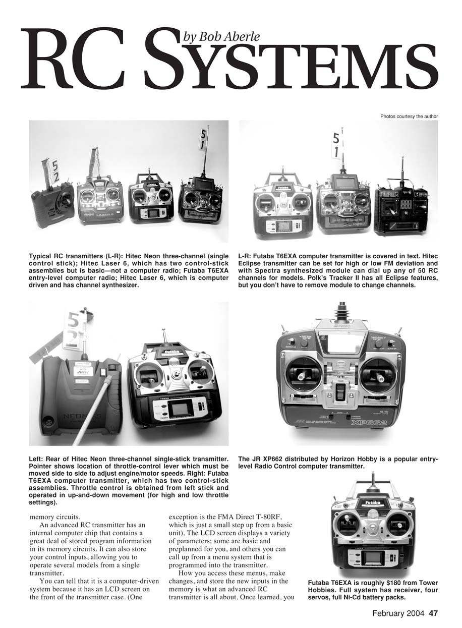
At the beginning of this series I discussed some of the basic radio control (RC) systems as an overall introduction to the model-aircraft hobby. To keep it simple and inexpensive, I selected a basic three-channel transmitter with a single control stick. I use several of these systems for my flying, so please don't worry; I didn't recommend that you buy something that would quickly become obsolete.
As the series progressed I described the Hitec Neon three-channel system, then the electric power system, and then the Aero Craft Pogo as a first-time (Almost Ready-to-Fly) training aircraft.
My student Jay Federman already had done a bit of flying on his own and owned a four-channel, dual-stick RC transmitter. When we flew the Pogo for the first time using a trainer cable, Jay had to hold the Neon transmitter since it was the one broadcasting the signal. The master control was my transmitter (a dual-stick-assembly four-channel unit), which I held as the instructor pilot.
Jay got confused because the throttle lever on the three-channel transmitter is on the rear of the case and operates with a side-to-side motion. He had done some flying using a left-side control stick that moved up for high speed and down for idle speeds. I recognized this problem right away, and many readers wrote in to "scold" me for having suggested a three-channel RC transmitter to a beginner. Admittedly, as you progress to four-channel ("full house," as we call it: elevator, aileron, rudder, and throttle control), the throttle control will be on the left stick and operated with an up-and-down motion. I guess some apologies are in order.
Just keep in mind that the three-channel RC system will never become obsolete. It is well suited for RC sailplanes, parking-lot flyers, and indoor RC.
I'm getting into more advanced RC systems at this time because eventually you will want to, and when you do you will quickly appreciate some of the extra features they can offer. Many of these advanced radios are simple to operate and are comparatively inexpensive. So let's get into it.
Basic versus computer-driven transmitters
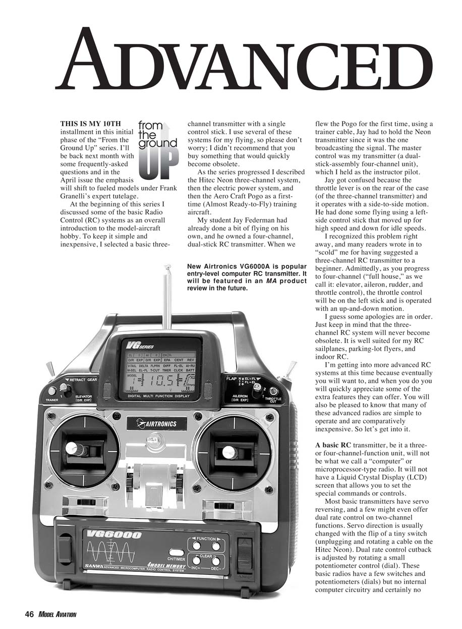
A basic RC transmitter, whether three- or four-channel, is not a "computer" radio. It will not have a liquid crystal display (LCD) screen for programming special commands or controls. Most basic transmitters have servo reversing; a few might offer dual-rate control on two-channel functions. Servo direction is usually changed with the flip of a tiny switch (or by unplugging and rotating a servo lead on some models). Dual-rate cutback is adjusted by rotating a small potentiometer (dial). These basic radios have a few switches and potentiometers but no internal computer circuitry or memory circuits.
An advanced RC transmitter has an internal computer chip and memory circuits. It can store your control inputs, allowing you to operate several models from a single transmitter. You can usually tell a computer-driven radio by its LCD screen. The screen displays a variety of parameters—some basic and preplanned, others available from a menu system programmed into the transmitter. How you access menus, make changes, and store the inputs in memory is what an advanced RC transmitter is all about. Once learned, an advanced radio is easy to use: it can store settings for several models and recall them instantly, saving you time.
Common features found in many computer radios include:
- model memory
- servo reversing
- subtrim
- end-point or servo-travel adjustment (EPA)
- dual rates
- exponential
- mixing (e.g., aileron-to-rudder, flap-to-elevator)
- programmable throttle curves
- flight-mode or switch-assignable mixes
- timers and trainer functions
- telemetry, voice alerts, and data logging (on some models)
You can start with an advanced RC transmitter but use only basic controls until you gain experience.
FM, AM, PCM, and deviation types
Most modern RC systems broadcast their signal using frequency modulation (FM). Only a few amplitude modulation (AM) systems remain on the market, and they are gradually disappearing. You cannot intermix signals: an FM transmitter cannot operate an AM receiver.
Within FM, manufacturers use two deviation types:
- FM deviation on the "low side" (used by Futaba, Hitec RCD, FMA Direct, and GWS)
- FM deviation on the "high side" (used by JR Remote Control and Airtronics)
A Futaba FM transmitter can operate Futaba FM receivers and FM receivers made by Hitec, FMA Direct, and GWS (on the same channel). A JR FM transmitter can operate JR and Airtronics FM receivers.
Some transmitters let you select "high" or "low" FM deviation, which allows broader compatibility across brands. More sophisticated transmitters use a synthesizer to dial up any of the 50 RC channels available for model aircraft.
There is also pulse code modulation (PCM), a technique that adds a digital code to the FM signal. PCM provides much greater interference rejection than regular FM and is usually found on top-of-the-line systems. PCM systems typically include a fail-safe feature that sets controls to preset positions and reduces engine throttle if interference is experienced. Each manufacturer uses its own dedicated PCM code, so transmitter and receiver must be the same brand (you cannot intermix PCM from different makers).
Types of Advanced RC Systems
Overview
You have already been introduced to the basic radio. There are also "first-step" computer-driven transmitters—entry-level systems offering many extra features, relatively easy to use, and comparatively inexpensive (full systems range from about $180 to $250). A further step into the computer-radio market offers systems from about $300 to $500 with more features and complexity. Top-of-the-line competition systems can cost $1,000 or more.
The first-step computer-radio system
All of the popular RC manufacturers—including Airtronics, FMA Direct, Futaba (Hobbico), Hitec RCD/Multiplex, and JR (Horizon Hobby)—offer entry-level computer radios. Mail-order hobby companies sometimes sell "house radios" that are generally manufactured by these companies.
Some notable first-step radios:
- Airtronics VG6000 (new, innovative menu system)
- Futaba T6EXA (simple and affordable—roughly $180)
- Hitec RCD Flash 5 X and Eclipse models
- JR XP662
You do not need to use the special features on these radios immediately. You can turn off or inhibit extras while you learn to fly your first models.
Futaba T6EXA
The heart of any computer-radio system is the transmitter. The six-channel Futaba T6EXA offers many useful features in a compact, relatively simple menu-driven layout. The manual is available from Futaba: www.futabarc.com/manuals/6exa-manual.pdf
Key features of the Futaba T6EXA:
- low-voltage alarm
- digital trims
- six model memory positions
- ability to reset any memory slot to factory-default positions
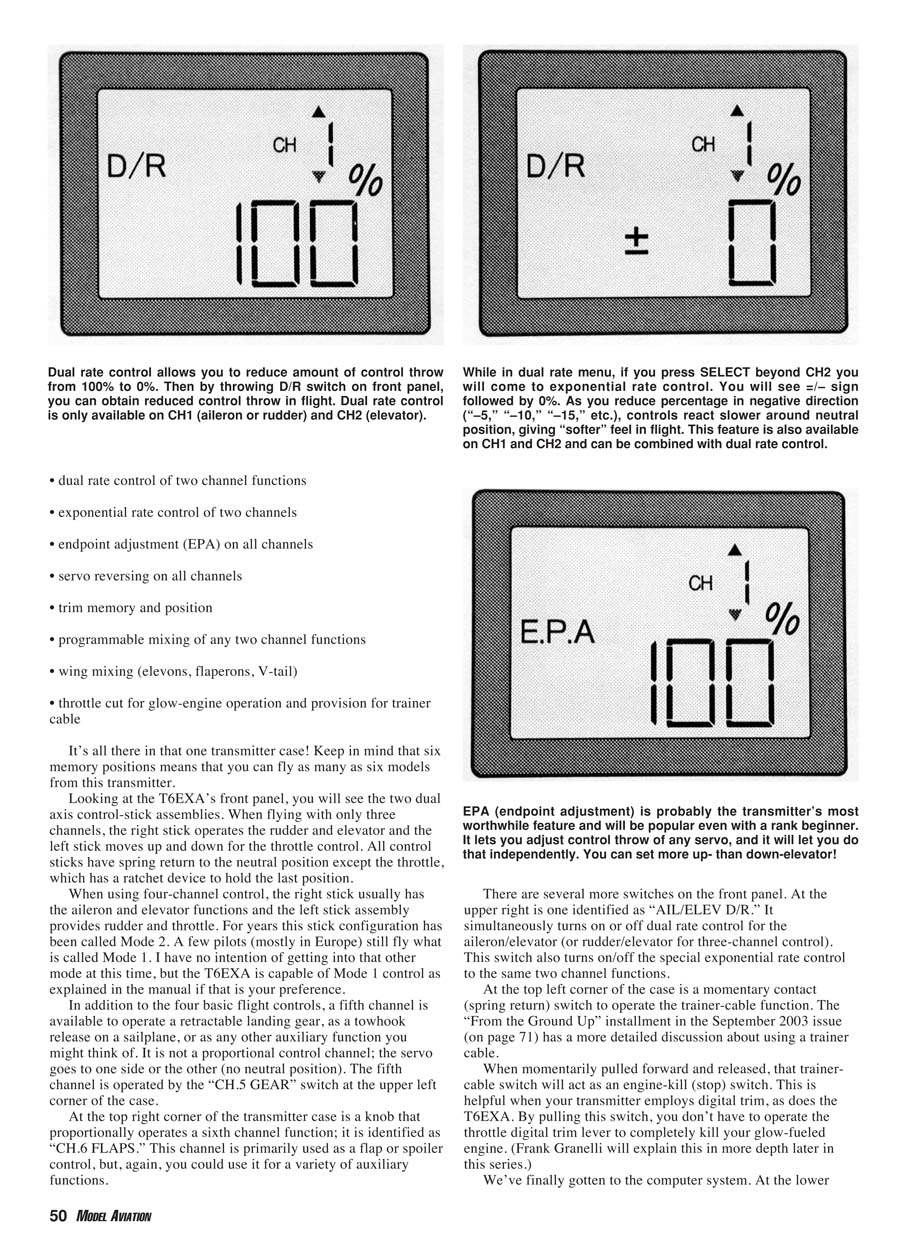
- dual-rate control of two channel functions
- exponential rate control of two channels
- endpoint adjustment (EPA) on all channels
- servo reversing on all channels
- trim memory and position display
- programmable mixing of any two channel functions
- wing mixing (elevons, flaperons, V-tail)
- throttle cut for glow-engine operation
- trainer-cable provision
Six memory positions means you can fly as many as six models from this transmitter.
Controls and layout:
- Two dual-axis control-stick assemblies. With three-channel models, the right stick operates rudder and elevator while the left stick moves side-to-side for throttle. For four-channel control (Mode 2), the right stick operates aileron and elevator while the left stick provides rudder and throttle.
- All control sticks have spring return to neutral except the throttle, which has a ratchet to hold position.
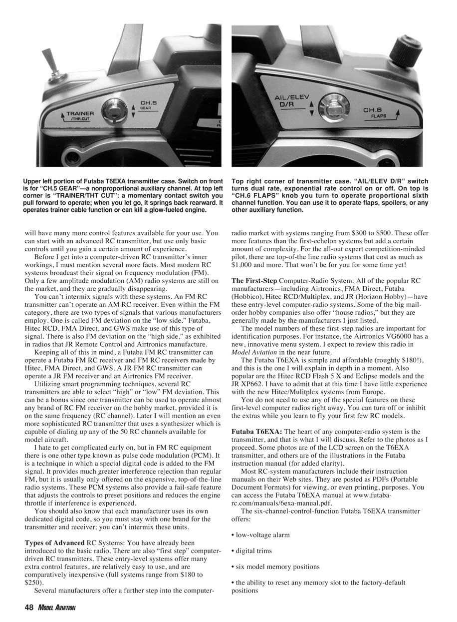
- Channel 5 (CH.5 GEAR) is a switch for non-proportional functions such as retracts or tow-hook release.
- Channel 6 (CH.6 FLAPS) is a proportional knob for flaps, spoilers, or other auxiliary functions.
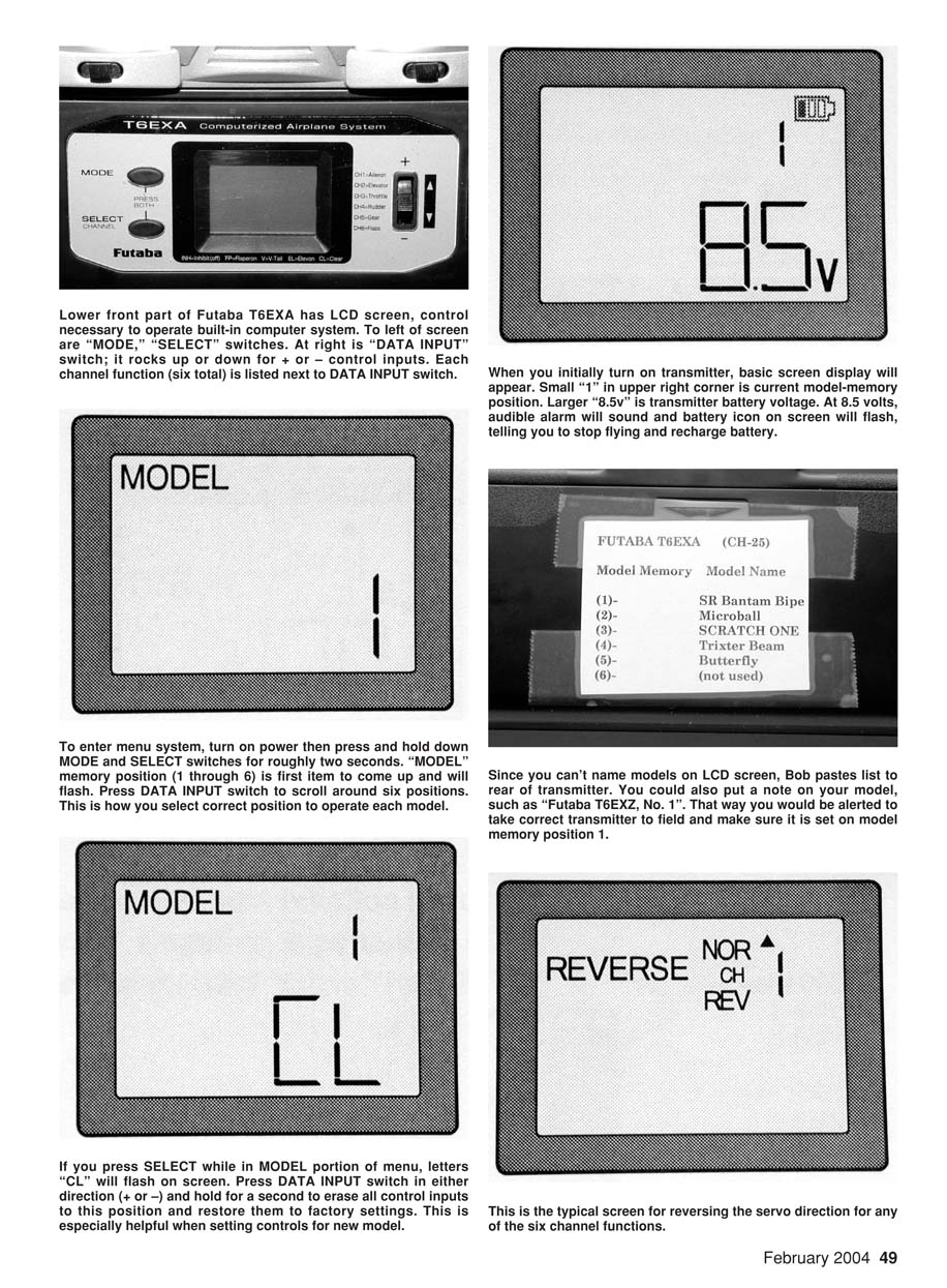
- An LCD screen sits in the lower-middle portion of the case. To the left of the screen are MODE and SELECT push-buttons. To the right is a DATA INPUT switch that rocks up (+) and down (–) for menu navigation and value changes. The six channels and their current assignments are displayed near the DATA INPUT switch.
- The transmitter displays the current model memory position (1–6) and the transmitter battery voltage (e.g., 10.0V). At about 8.5V an audible alarm sounds and a battery icon flashes—land immediately and recharge or swap packs.
Accessing the menu:
- With power on, press and hold MODE and SELECT for about two seconds to enter the menu.
- MODEL memory appears first; use DATA INPUT (+/–) to select model positions 1–6.
- Press SELECT while in MODEL to display "CL" (clear). Holding DATA INPUT (+ or –) for about two seconds erases that memory and restores factory defaults—handy when setting up a new model.
- REVERSE allows you to reverse servo direction for channels 1–6 (use SELECT to choose channel, DATA INPUT to set NOR or REV).
- D/R (Dual Rate) applies to channels 1 (aileron or rudder in three-channel mode) and 2 (elevator). Use SELECT to pick CH1 or CH2 and DATA INPUT to set percent throw (100% is full). The AIL/ELEV D/R switch toggles between full and reduced throws. On the T6EXA, aileron and elevator dual rates are switched together (cannot be separated).
- Exponential (EXP) appears under the D/R function. EXP uses positive/negative values; negative numbers soften initial response around neutral. You can combine dual rate and exponential or use them separately.
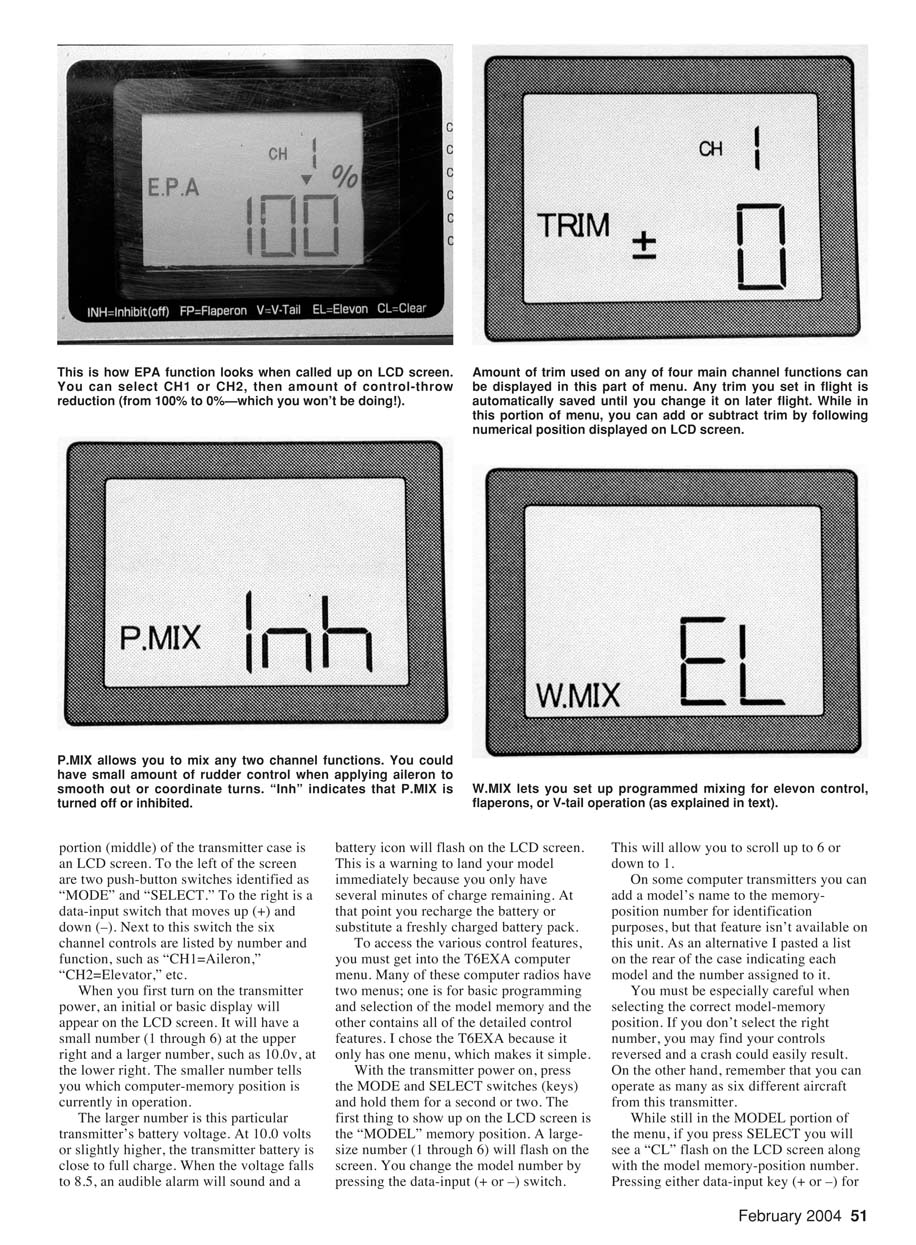
- EPA (endpoint adjustment) is available on all six channels. EPA lets you set servo throw precisely and independently—e.g., more up than down elevator or asymmetrical aileron throws. EPA is especially useful on throttle for fine carburetor adjustments on fueled engines.
- TRIM displays and stores digital trim positions for the main channels (aileron, elevator, rudder, throttle). Trim values are stored with the model memory. On the T6EXA, channels 5 and 6 do not have trim. The throttle trim only operates when the throttle stick is near minimum, allowing a low-idle setting without stalling a glow engine.
- Programmable mixing ("P.MIX") lets you combine any two functions—for example, aileron-to-rudder coupling. Wing mixes ("W.MIX") provide elevons (EL), flaperons (FP), or V-tail (V) mixing.
- The menu loops continuously; if you miss an item, keep pressing MODE until it appears again.
As you navigate and make adjustments, inputs are saved automatically when you move to the next menu item or turn power off. Calling up a model memory position restores the stored settings.
Power and batteries
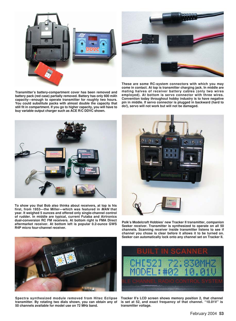
Many computer transmitters draw upward of 200 mA. While 600 mAh NiCd packs were common, NiMH AA packs with capacities up to 1100 mAh and more are now standard and available from vendors such as Batteries America and SR Batteries. Use the proper mating connector for your transmitter brand.
Charging: remember to charge NiMH packs at C/10 (capacity divided by 10). For example, an 1100 mAh battery should be charged at about 110 mA—usually an overnight charge on a variable-output charger (e.g., Ace R/C Digital Dual Variable Charger).
Synthesizers and multi-channel scanning
A number of computer transmitters use a synthesizer so you can dial up any of the 50 RC channels available for aircraft. Hitec’s Eclipse with the Spectra synthesized module is one example: the module plugs into the transmitter and its dials select channels 11–60. The Eclipse also lets you select high or low FM deviation, enabling broader receiver compatibility.
Other radios go further: Polk’s Modelcraft Tracker II accommodates more than 90 memory positions and lets you select any of the 50 channels from the LCD screen (no module removal required). The Tracker II also scans the operating channel on power-up to confirm it's clear before going on the air. Polk’s Seeker receiver can listen for an FM signal and set itself to that channel—useful for switching channels frequently without waiting for an open frequency.
Mixing and aftermarket components
The ability to store control data for many models means you'll need multiple receivers (one per aircraft) but only one transmitter. Manufacturers typically sell airborne packs (receiver and servos) with their systems, and historically have priced them competitively. More recently, aftermarket receivers and servos that work with many computer-driven transmitters have become common. FMA Direct offers a complete line, including micro dual-conversion receivers (e.g., the M5, weighing 0.35 ounce). Using aftermarket micro receivers and micro servos is commonplace for parking-lot and indoor RC flyers.
Connector polarity conventions have largely standardized on three-pin servo connectors: one outside pin is battery negative, the center pin is battery positive, and the other outside pin is the signal. Some connectors are keyed to prevent reversal. The one lingering exception is the JR transmitter charger plug, where center/outside polarity differs from other industry plugs.
For the more advanced RC pilot
Most of us fly on one of the 50 RC channels allocated by the FCC for model aircraft. With 50 channels and synthesizer-equipped radios, you rarely have to wait long to fly. However, local flying fields sometimes have channel concentration. One way to avoid a "channel traffic jam" is to obtain an FCC amateur radio (ham) license and operate on the Amateur Radio Service 6-meter band (50 MHz). Many manufacturers offer ten-channel systems near 50 MHz for this purpose.
If you're interested in becoming a ham and flying on your own channel, contact the American Radio Relay League (ARRL): 225 Main St., Newington CT 06111; Tel.: (800) 594-0200; www.arrl.org.
Closing and upcoming topics
My articles in this series began in the March 2003 Model Aviation. Look for Frank Granelli’s glow-fueled-model input in coming months. I expect to do several guest spots on parking-lot/backyard flying, indoor RC, lithium-polymer batteries and their applications, and a frequently-asked-questions installment next month.
This series is posted on the Model Aviation portion of the AMA’s website: http://modelaircraft.org/mag/index.htm.
MA Bob Aberle
Manufacturers
- Ace Hobby Distributors, Inc.
2055 Main St., Irvine CA 92614 Tel: (949) 833-0088; Fax: (949) 833-0003 www.acehobby.com
- Airtronics Inc.
1185 Stanford Ct., Anaheim CA 92805 Tel: (714) 978-1895 [email protected] www.airtronics.net
- Batteries America
2211-D Parview Rd., Middleton WI 53562 Tel: (800) 308-4805 [email protected] www.batteriesamerica.com
- FMA Direct
5716A Industry Ln., Frederick MD 21704 Tel: (800) 343-2934; Fax: (301) 668-7619 [email protected] www.fmadirect.com
- GWS (also sold by Horizon Hobby, Balsa Products)
22 Jansen Ave., Iselin NJ 08830 Tel: (732) 634-6131 www.balsapr.com
- Hitec RCD (and Multiplex)
12115 Paine St., Poway CA 92064 Tel: (858) 748-6948 www.hitecrcd.com
- JR Remote Control / Horizon Hobby Inc.
4105 Fieldstone Rd., Champaign IL 61822 Tel: (217) 355-9511 www.horizonhobby.com
- SR Batteries Inc.
Box 287, Bellport NY 11713 Tel: (631) 286-0079; Fax: (631) 286-0901 [email protected] www.srbatteries.com
- Tower Hobbies (Hobbico and Futaba radios)
Box 9078, Champaign IL 61826 Tel: (800) 637-6050 www.towerhobbies.com
Transcribed from original scans by AI. Minor OCR errors may remain.

