
From the Ground Up - Engines 101 - 2004/04
by Frank Granelli
Introduction
Bob Aberle conceived the "From the Ground Up" article series to help new pilots get the most from their radio-control modeling experience. His concept and the first two parts—radios and electric power—were highly successful. This installment continues the series with engines, the most common way to get an airplane off the ground.
My goal is to present engines and their related systems in enough detail to let you forget about the engine while you learn to fly. Topics I will cover include:
- selecting and installing the correct engine
- mufflers, spinners, and propellers
- break-in and tuning techniques
- fuel, fuel tanks and supply lines
- support equipment, maintenance, and minor repair
- safety practices
If you follow sound radio advice and fly with an instructor (always recommended), engine failure too far from the runway is one of the main causes of damage to your trainer. Reliable engine operation speeds your flight training and reduces unnecessary repairs.
What is an engine?
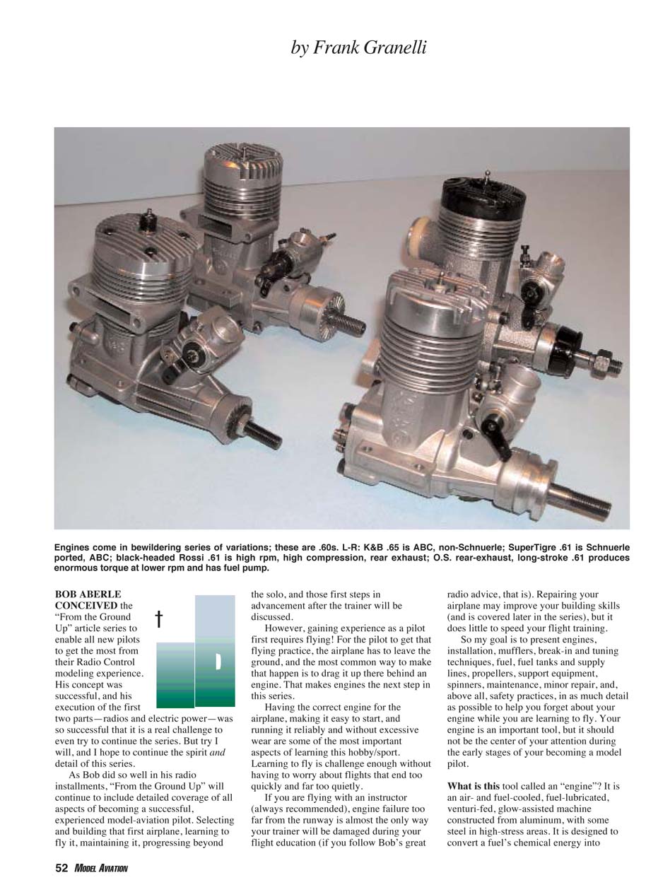
A model aircraft engine is an air- and fuel-cooled, fuel-lubricated, venturi-fed, glow-assisted machine, usually constructed from aluminum with steel in high-stress areas. It converts a fuel’s chemical energy into rotational motion to turn a propeller.
Considering each part of that description helps you avoid common engine problems. Converting fuel to mechanical energy produces heat, which must be removed or the engine will overheat and fail.
Cooling and lubrication
- Model engines are primarily air-cooled. Propeller airflow is directed over fins on the engine to remove heat. Air is a poor heat exchanger compared with liquids, and it only contacts the engine surface briefly, so cooling is inherently less efficient.
- Fuel provides additional cooling. As fuel vaporizes in the carburetor, its temperature and density drop, helping to cool the intake and lower crankcase areas. Any unburnt alcohol in the exhaust carries heat away as droplets.
- Most important: fuel is the engine's sole lubrication source. Model fuel contains oil that lubricates moving parts and reduces friction and temperature. Unlike automobile engines with separate oil systems, lubrication in model engines depends entirely on fuel flow (the mixture setting).
Fuel, mixture and carburetion
- An engine's maximum air supply is fixed by the carburetor opening diameter and adjusted by the throttle barrel.
- The pilot adjusts fuel flow relative to incoming air using high- and low-speed needle valves and/or air-bleed adjustment screws.
- Proper adjustment of these fuel-metering devices controls the engine's operating temperature, reliability, and durability—regardless of whether the engine is a two-stroke or four-stroke.
Two-stroke engines
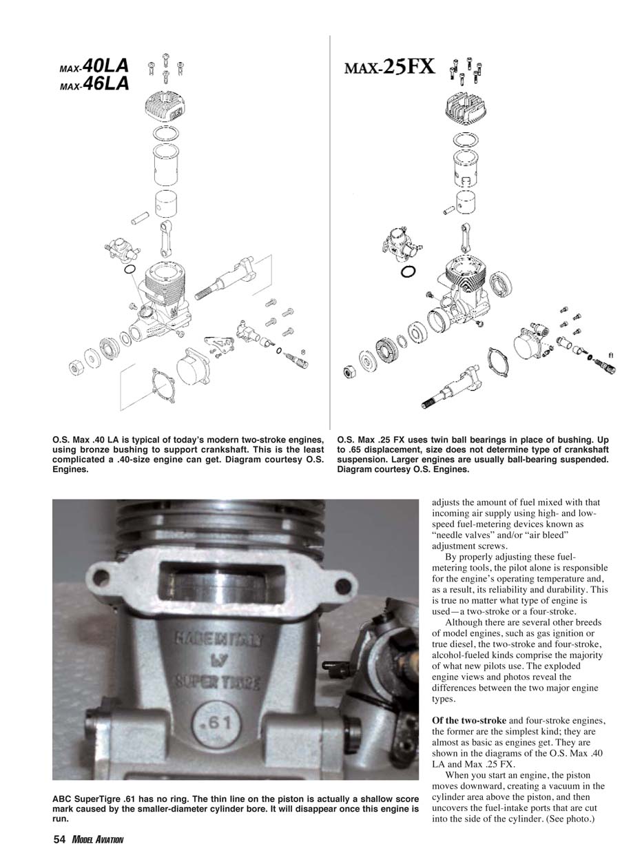
Two-stroke engines are the simplest and are very common for trainers. They are simple, lightweight, and powerful for their size.
Two-stroke operation
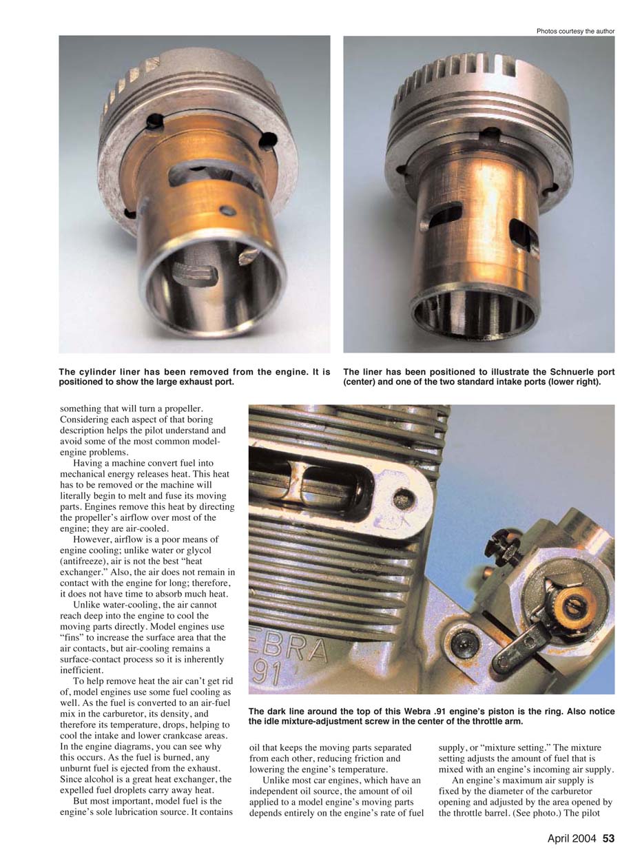
- On the downward stroke the piston creates a vacuum above it and uncovers intake ports cut in the cylinder wall. The piston then uncovers transfer ports that allow the fuel–air charge in the crankcase to enter the cylinder.
- On the upward stroke the piston compresses the mixture against the glow plug. The glow plug ignites the mixture, producing a power stroke that drives the piston downward.
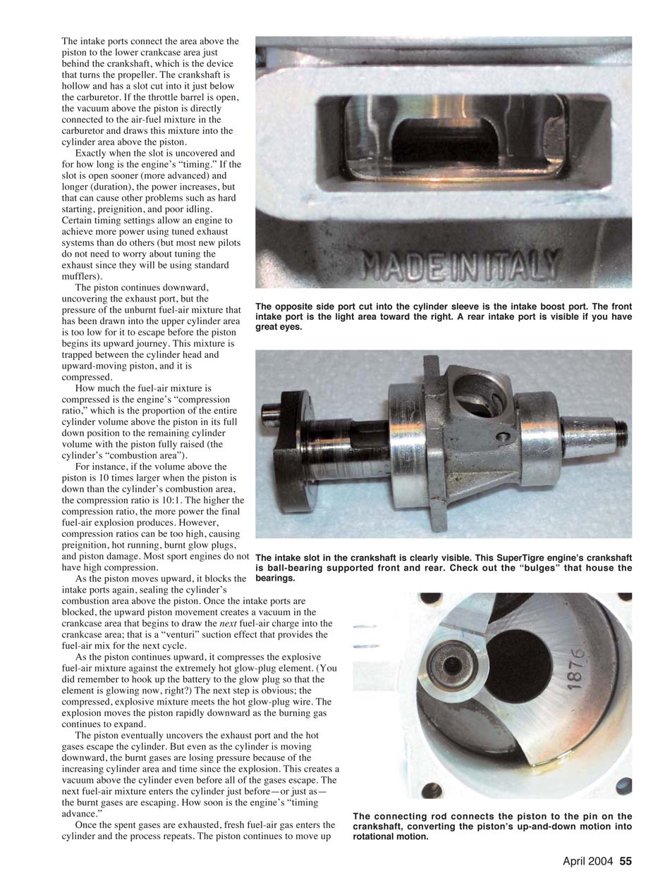
- The two-stroke completes a power stroke every revolution of the crankshaft (one power stroke per revolution), converting reciprocating motion to rotation via the connecting rod.
- The crankshaft is often hollow and includes a slot below the carburetor; when uncovered, this slot times the transfer of mixtures from the carburetor/crankcase into the cylinder.
Timing and compression ratio
- Timing: exactly when the crankshaft slot or ports open and for how long determines engine timing. More advanced timing (opening earlier or longer) can increase power but may cause hard starting, preignition, or poor idling.
- Compression ratio: the ratio of the cylinder volume when the piston is at bottom dead center to the combustion volume at top dead center. Higher compression ratios increase power but can cause preignition, hot running, burnt glow plugs, and piston damage. Most sport engines have moderate compression.
Displacement and porting
- Engine displacement is the total volume the piston displaces during its stroke (stroke length × cylinder area).
- Most trainer two-stroke sport engines range from .25 to .61 cubic inch displacement. Larger displacement provides more power and permits larger propellers but increases fuel consumption and cost.
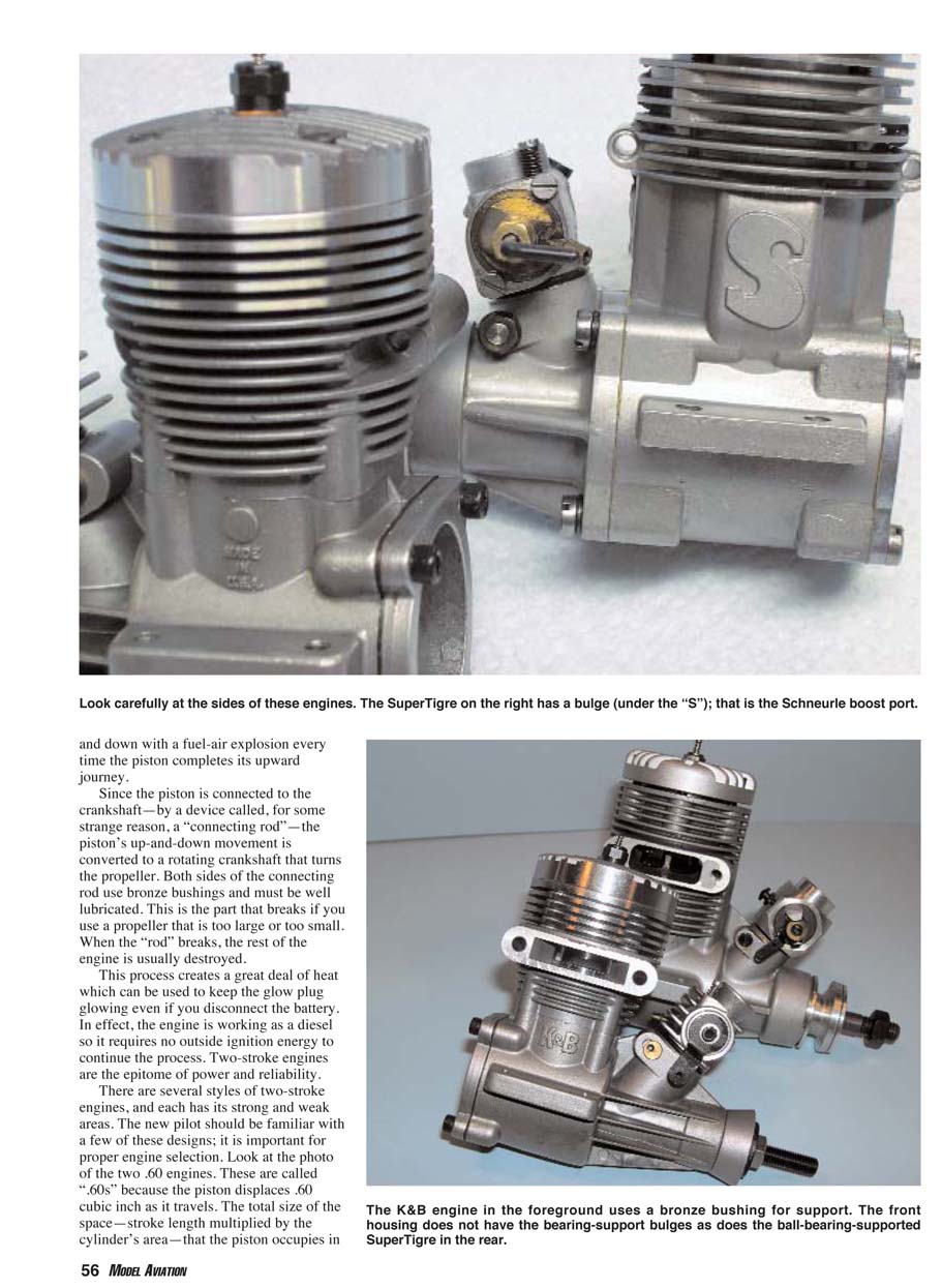
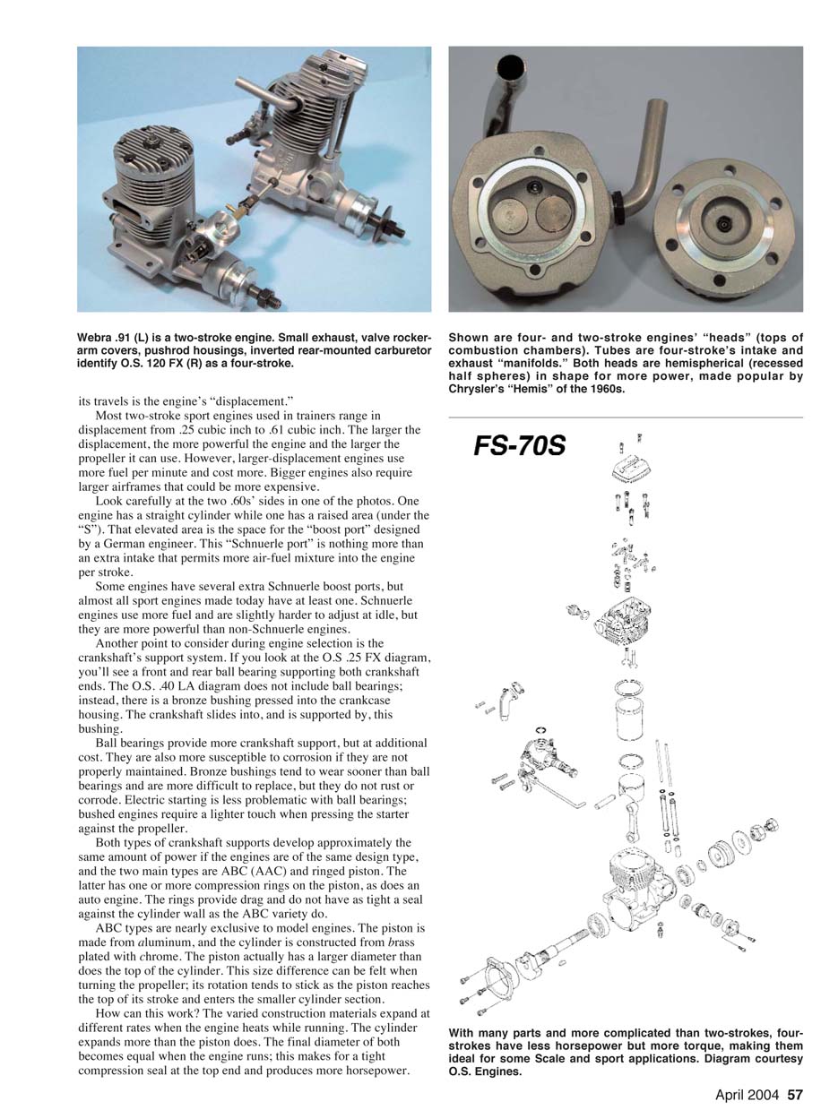
- Many engines use Schnuerle (boost) ports—extra transfer ports that allow more air–fuel mixture into the cylinder per stroke. Schnuerle designs are more powerful and use more fuel; they can be slightly harder to adjust at idle.
Crankshaft support and piston types
- Crankshaft support typically uses either ball bearings or bronze bushings:
- Ball bearings: provide better crankshaft support and favor electric starting but are more susceptible to corrosion if not maintained.
- Bronze bushings (bushed engines): resist corrosion but wear sooner and are harder to replace; require a lighter touch with electric starters.
- Piston types:
- ABC (or AAC): aluminum piston with a brass (or aluminum) sleeve, often chrome-plated. The piston is initially slightly larger than the cylinder bore; as the engine warms, the cylinder expands more than the piston to create a tight seal. ABC engines are common up to about .61 cu in.
- Ringed pistons: use compression rings similar to automobile engines, offer slightly different sealing and torque characteristics and are more common in larger engines.
- The connecting rod uses bronze bushings on both ends and must be well lubricated. A broken connecting rod usually destroys the rest of the engine; incorrect propeller sizing (too large or too small) can cause rod failure.
Most new pilots start with two-stroke engines because they are simple, reliable, inexpensive, and powerful. Ready-to-Fly (RTF) trainers almost always use two-strokes (except some electric models).
Four-stroke engines
Many pilots prefer four-stroke engines for their sound, fuel efficiency, and higher torque. Four-stroke trainers are usually installed by pilots who buy Almost Ready-to-Fly (ARF) trainers and install engines and radio gear themselves.
Four-stroke operation
- Model four-strokes are air-cooled and glow-assisted but still fuel-lubricated.
- Fuel–air mixture is created in a carburetor and drawn into the combustion chamber through an intake manifold and an intake valve, not through crankcase transfer ports.
- A camshaft, driven by the crankshaft via timing gears, controls valve opening and closing. Pushrods and other valve-train components actuate the valves (details of valve operation and maintenance will be covered in a later article).
- Four-stroke engines produce one power stroke every other revolution of the crankshaft.
Four-stroke vs two-stroke
- A four-stroke generally produces about 75–80% of the horsepower of an equivalent-displacement two-stroke, but modern design improvements have narrowed the performance gap.
- Four-strokes deliver more torque for a given displacement, are easier to adjust, and tolerate timing advances well. Extra torque allows four-strokes to turn larger-diameter propellers (with equivalent pitch) safely.
- Four-strokes are quieter and have a lower-pitched exhaust note due to lower rpm.
Propellers and practical horsepower ratings
Two-stroke horsepower ratings are often measured at very high rpm with small props and have limited practical use for trainer selection. Large, high-rpm props can stall on high-drag trainer airframes, producing little thrust. I will cover propeller selection, propeller stall, and spinner use in detail in future installments.
What I will cover next
The next installment will focus on setup, installation, adjustment, propellers, and the care and feeding of the popular .40-cubic-inch, two-stroke engine. Future articles will include detailed coverage of four-stroke care, exhaust tuning, field accessories, tools, fuel types, and many other practical subjects.
You may not become a model-engine expert, but you will learn what you need to choose an engine, keep it running reliably, make it last, and get the best flying performance from your model.
Author
Frank Granelli 24 Old Middletown Rd. Rockaway, NJ 07866
Transcribed from original scans by AI. Minor OCR errors may remain.

