
From the Ground Up: Not Your Stock Hobbistar MK III
Frank Granelli
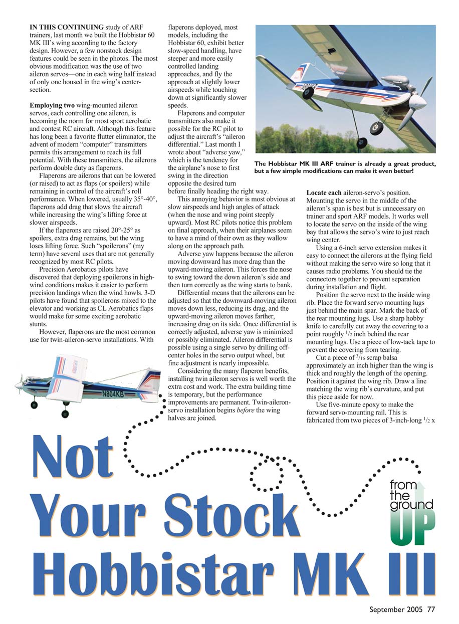
IN THIS CONTINUING study of ARF trainers, last month we built the Hobbistar 60 MK III's wing according to the factory design. However, a few nonstock design features could be seen in the photos. The most obvious modification was the use of two aileron servos—one in each wing half instead of only one housed in the wing's centersection.
Employing two wing-mounted aileron servos, each controlling one aileron, is becoming the norm for most sport aerobatic and contest RC aircraft. Although this feature has long been a favorite flutter eliminator, the advent of modern "computer" transmitters permits this arrangement to reach its full potential. With these transmitters, the ailerons perform double duty as flaperons.
Flaperons are ailerons that can be lowered (or raised) to act as flaps (or spoilers) while remaining in control of the aircraft's roll performance. When lowered, usually 35°–40°, flaperons add drag that slows the aircraft while increasing the wing's lifting force at slower airspeeds.
If the flaperons are raised 20°–25° as spoilers, extra drag remains, but the wing loses lifting force. Such "spoilerons" (my term) have several uses that are not generally recognized by most RC pilots.
Precision Aerobatics pilots have discovered that deploying spoilerons in highwind conditions makes it easier to perform precision landings when the wind howls. 3-D pilots have found that spoilerons mixed to the elevator and working as CL Aerobatics flaps would make for some exciting aerobatic stunts.
However, flaperons are the most common use for twin-aileron-servo installations. With flaperons deployed, most models, including the Hobbistar 60, exhibit better slow-speed handling, have steeper and more easily controlled landing approaches, and fly the approach at slightly lower airspeeds while touching down at significantly slower speeds.
Flaperons and computer transmitters also make it possible for the RC pilot to adjust the aircraft's "aileron differential." Last month I wrote about "adverse yaw," which is the tendency for the airplane's nose to first swing in the direction opposite the desired turn before finally heading the right way.
This annoying behavior is most obvious at slow airspeeds and high angles of attack (when the nose and wing point steeply upward). Most RC pilots notice this problem on final approach, when their airplanes seem to have a mind of their own as they wallow along on the approach path.
Adverse yaw happens because the aileron moving downward has more drag than the upward-moving aileron. This forces the nose to swing toward the downward aileron's side and to turn correctly as the wing starts to bank.
Differential means that the ailerons can be adjusted so that the downward-moving aileron moves down less, reducing its drag, and the upward-moving aileron moves farther, increasing drag on its side. Once differential is correctly adjusted, adverse yaw is minimized or possibly eliminated. Aileron differential is possible using a single servo by drilling off-center holes in the servo output wheel, but fine adjustment is nearly impossible.
Considering the many flaperon benefits, installing twin aileron servos is well worth the extra cost and work. The extra building time is temporary, but the performance improvements are permanent. Twin-aileron-servo installation begins before the wing halves are joined.
Locate each aileron-servo's position. Mounting the servo in the middle of the aileron's span is best but is unnecessary on trainer and sport ARF models. It works well to locate the servo on the inside of the wing bay that allows the servo's wire to just reach wing center.
Using a 6-inch servo extension makes it easy to connect the ailerons at the flying field without making the servo wire so long that it causes radio problems. You should tie the connectors together to prevent separation during installation and flight.
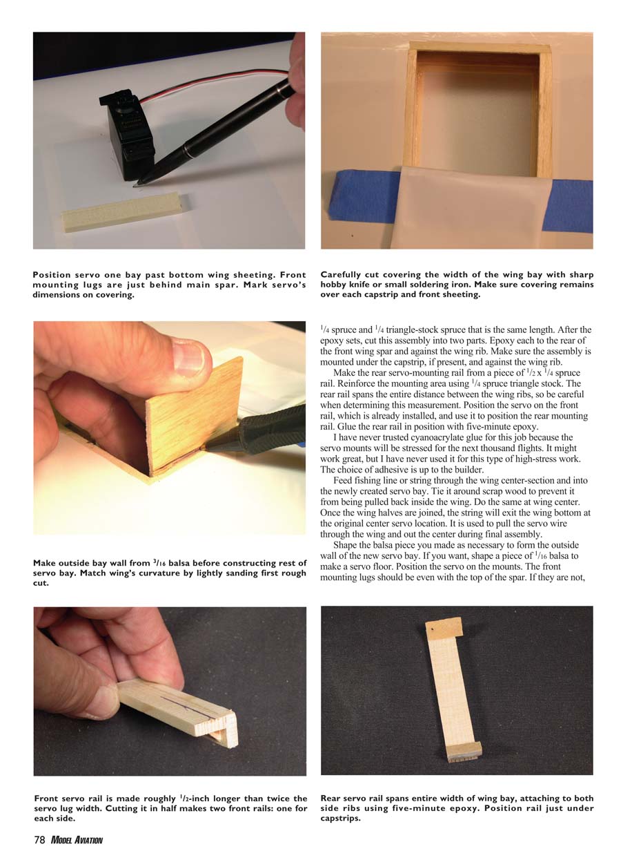
Position the servo next to the inside wing rib. Place the forward servo mounting lugs just behind the main spar. Mark the back of the rear mounting lugs. Use a sharp hobby knife to carefully cut away the covering to a point roughly 1/2 inch behind the rear mounting lugs. Use a piece of low-tack tape to prevent the covering from tearing.
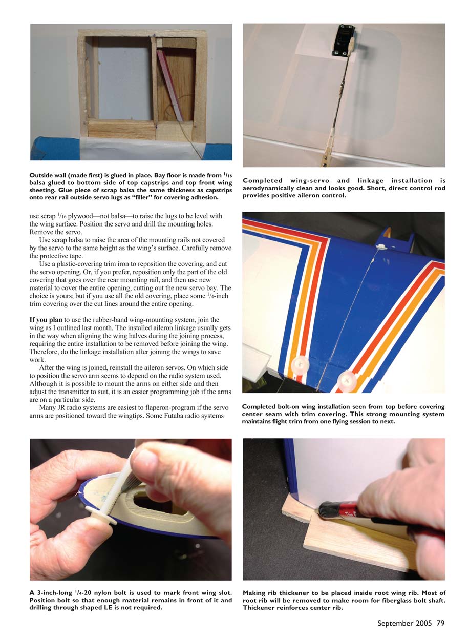
Cut a piece of 3/16 scrap balsa approximately an inch higher than the wing is thick and roughly the length of the opening. Position it against the wing rib. Draw a line matching the wing rib's curvature, and put this piece aside for now.
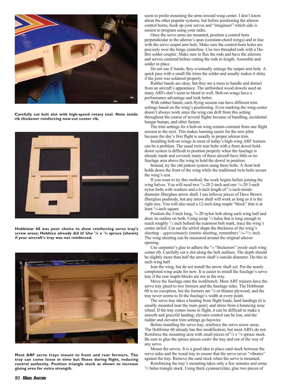
Use five-minute epoxy to make the forward servo-mounting rail. This is fabricated from two pieces of 3-inch-long 1/2 x 1/4 spruce and 1/4 triangle-stock spruce that is the same length. After the epoxy sets, cut this assembly into two parts. Epoxy each to the rear of the front wing spar and against the wing rib. Make sure the assembly is mounted under the capstrip, if present, and against the wing rib.
Make the rear servo-mounting rail from a piece of 1/2 x 1/4 spruce rail. Reinforce the mounting area using 1/4 spruce triangle stock. The rear rail spans the entire distance between the wing ribs, so be careful when determining this measurement. Position the servo on the front rail, which is already installed, and use it to position the rear mounting rail. Glue the rear rail in position with five-minute epoxy.
I have never trusted cyanoacrylate glue for this job because the servo mounts will be stressed for the next thousand flights. It might work great, but I have never used it for this type of high-stress work. The choice of adhesive is up to the builder.
Feed fishing line or string through the wing center-section and into the newly created servo bay. Tie it around scrap wood to prevent it from being pulled back inside the wing. Do the same at wing center. Once the wing halves are joined, the string will exit the wing bottom at the original center servo location. It is used to pull the servo wire through the wing and out the center during final assembly.
Shape the balsa piece you made as necessary to form the outside wall of the new servo bay. If you want, shape a piece of 1/16 balsa to make a servo floor. Position the servo on the mounts. The front mounting lugs should be even with the top of the spar. If they are not, use scrap 1/16 plywood—not balsa—to raise the lugs to be level with the wing surface. Position the servo and drill the mounting holes. Remove the servo.
Use scrap balsa to raise the area of the mounting rails not covered by the servo to the same height as the wing's surface. Carefully remove the protective tape.
Use a plastic-covering trim iron to reposition the covering, and cut the servo opening. Or, if you prefer, reposition only the part of the old covering that goes over the rear mounting rail, and then use new material to cover the entire opening, cutting out the new servo bay. The choice is yours; but if you use all the old covering, place some 1/4-inch trim covering over the cut lines around the entire opening.
If you plan to use the rubber-band wing-mounting system, join the wing as I outlined last month. The installed aileron linkage usually gets in the way when aligning the wing halves during the joining process, requiring the entire installation to be removed before joining the wing. Therefore, do the linkage installation after joining the wings to save work.
After the wing is joined, reinstall the aileron servos. On which side to position the servo arm seems to depend on the radio system used. Although it is possible to mount the arms on either side and then adjust the transmitter to suit, it is an easier programming job if the arms are on a particular side.
Many JR radio systems are easiest to flaperon-program if the servo arms are positioned toward the wingtips. Some Futaba radio systems seem to prefer mounting the arms toward wing center. I don't know about the other popular systems, but before positioning the aileron control horns, hook up your servos and "imagineer" which side is easiest to program using your radio.
Once the servo arms are mounted, position a control horn perpendicular to the aileron's span (constant-chord wings) and in line with the servo output arm hole. Make sure the control-horn holes are precisely over the hinge centerline. Use two threaded rods with a Du-Bro solder coupler. Make sure to flux the rods and have the ailerons and servos centered before cutting the rods to length. Assemble and solder in place.
Do not use Z bends; they eventually enlarge the output arm hole. A quick pass with a small file trims the solder and usually makes it shiny if the joint was soldered properly.
Rubber bands are okay, but they are a mess to handle and detract from an aircraft's appearance. The unfinished wood dowels used on many ARFs don't seem to blend in well. Bolt-on wings have a performance advantage and look better.
With rubber bands, each flying session can have different trim settings based on the wing's positioning. Even marking the wing center doesn't always work since the wing can drift from this setting throughout the course of several flights because of handling, accidental hangar bumps, and other factors.
The trim settings for a bolt-on wing remain constant from one flight session to the next. This makes learning easier for the new pilot because the day's first flight is usually in proper aileron trim.
Installing bolt-on wings in most of today's high-wing ARF trainers can be a problem. The usual twin rear bolts with a front dowel hold-down system is difficult to position properly when the fuselage is already made and covered; many of these aircraft have little or no fuselage area above the wing to hold the dowel in position.
Instead, try the old pattern system using three bolts. A front bolt holds down the front of the wing while the traditional twin bolts secure the wing's rear.
If you want to try this method, the work begins before joining the wing halves. You will need two 1/4-20 2-inch and one 1/4-20 3-inch nylon bolts with washers and a 6-inch length of 1/4-inch-inside-diameter fiberglass arrow shaft. I use leftover pieces of Dave Brown fiberglass pushrods, but any arrow shaft will work as long as it is the right size. You will also need a 12-inch-long maple "block" that is at least 3/4-inch square.
Position the 3-inch long, 1/4-20 nylon bolt along each wing half and draw its outline on both. Using scrap 1/4 balsa that is long enough to reach roughly 1/2 inch behind the rearmost bolt mark, trace the wing's center airfoil. Cut out the airfoil shape the thickness of the wing's sheeting—approximately (metric sheeting, remember) 1/16–3/32 inch. The wing sheeting can be measured around the original aileron opening.
Use carpenter's glue to adhere the 1/4 thickeners inside each wing center rib. Carefully cut a slot along the bolt outlines. The depth should be slightly more than half the arrow shaft's outside diameter. Do this in each wing half.
Join the wing, but do not install the arrow shaft yet. Put the nearly completed wing aside for now. It is easier to install the fuselage's servo tray if the rear maple blocks are not in the way.
Move the fuselage onto the workbench. Most ARF trainers have the servo tray glued to two formers and the fuselage sides. The Hobbistar 60 is no exception, but the formers are 1/8 or thinner plywood, and the tray never seems to fit the fuselage's width at every point.
The servo tray takes a beating from flight loads, hard landings (it is usually mounted near the main gear), and stress from a bouncing nose wheel. If the tray comes loose in flight, it can be difficult to make a smooth and graceful landing; elevator control can be lost, and the rudder and elevator trim settings go haywire.
Before installing the servo tray, reinforce the servo screw areas. The Hobbistar 60 already has this modification, but most ARFs do not. Reinforce the mounting area with small pieces of 1/4 x 1/8 spruce stock. Be sure to glue the spruce pieces under the tray and out of the way of any servo.
Mount the servos. It is a good idea to place card stock between the servo sides and the wood tray to ensure that the servo never "vibrates" against the tray. Remove the card stock when the servos are mounted.
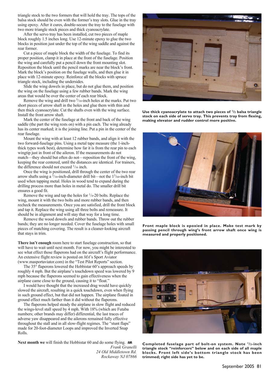
Reinforcing the tray's mounting takes only a few minutes and some 1/2 balsa triangle stock. Using thick cyanoacrylate, glue two pieces of triangle stock to the fuselage sides, then glue the servo tray to the formers and triangle supports. Sand the tray to make sure it is flush and even with the fuselage sides.
With the servos installed and the tray reinforced, hook up the controls. Use high-quality pushrods and Du-Bro-type clevises. Check every connection for security, and use thread-lock where metal-to-metal connections are present.
Install the nylon front bolt and the fiberglass arrow shaft dowel. The maple block rests against the fuselage former and takes the compressive load when the wing is bolted down. The result is a rigid, secure bolt-on wing that is easy to install and remove yet a better solution than rubber bands or flimsy dowels.
Finish the fuselage by installing the canopy and any remaining hardware. Balance the aircraft at the recommended center of gravity; if none is given, start at about 25 percent of the mean aerodynamic chord and adjust from there.
After a range check and control-surface direction verification, take the Hobbistar 60 out for its first flight. Trim as necessary and enjoy the improved handling and durability of your reinforced and properly mounted ARF trainer.
There isn't enough room here to start fuselage construction, so that will have to wait until next month. For now, you might be interested to see what effect those flaperons had on the aircraft's flight performance. An extensive flight review is posted on MA's Sport Aviator (www.masportaviator.com) in the "Test Pilot Reports" section.
The 35° flaperons lowered the Hobbistar 60's approach speeds by roughly 4 mph. But the airplane's touchdown speed was lowered by 9 mph because the flaperons seemed to gain effectiveness when the airplane came close to the ground, causing it to "float."
I would have thought that the increased drag would have quickly slowed the aircraft, resulting in a quick touchdown, even when flying in such ground effect, but that did not happen. The airplane floated in ground effect much farther than it did without the flaperons.
The flaperons helped steady the airplane in slow flight and reduced the wings-level stall speed by 4 mph. With 18% (which are Futaba numbers; other brands may differ) differential, the last traces of adverse yaw disappeared and the ailerons remained fully effective throughout the stall and in all slow-flight regimes. The "stunt flaps" made for 20-foot-diameter Loops and improved the Inverted Snap Rolls.
Next month we will finish the Hobbistar 60 and do some flying.
Frank Granelli 24 Old Middletown Rd. Rockaway NJ 07866
Transcribed from original scans by AI. Minor OCR errors may remain.

