
From the Ground Up: Not Your Stock Hobbistar MK III
Frank Granelli
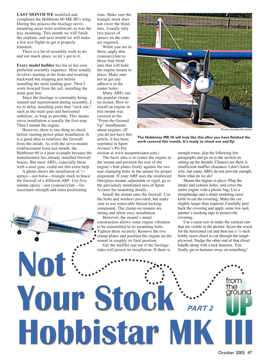
LAST MONTH WE modified and completed the Hobbistar 60 MK III's wing. During this process the fuselage servo-mounting areas were reinforced, as was the tray mounting. This month we will finish the airplane, and next month we will make a few test flights to get it properly trimmed.
There is a lot of assembly work to do and not much space, so let's get to it.
Every model builder has his or her own preferred assembly sequence. Mine usually involves starting at the front and working backward but stopping just before installing the main landing gear. Then I work forward from the tail, installing the main gear last.
Since the fuselage is constantly being rotated and repositioned during assembly, I try to delay installing parts that "stick out," such as the main gear and horizontal stabilizer, as long as possible. This means servo installation is usually the first step. Then I mount the engine.
However, there is one thing to check before starting power-plant installation. It is a good idea to reinforce the firewall from the inside. As with the servo-mount reinforcement from last month, the Hobbistar 60 is a poor example because the manufacturer has already installed firewall braces. But most ARFs, especially those with a nose gear, could use this extra help.
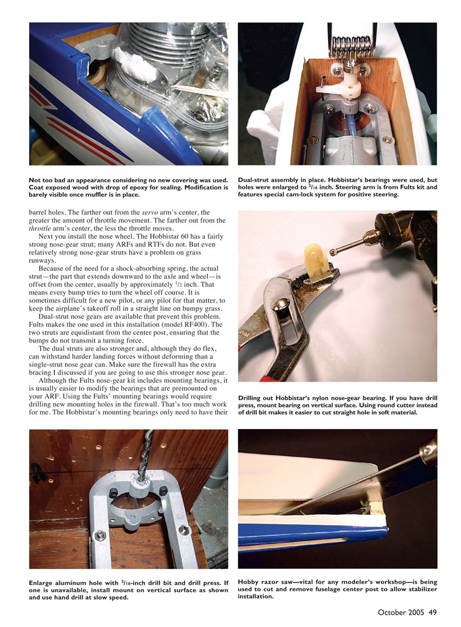
A photo shows the installation of 1/2" spruce—not balsa—triangle stock to brace the firewall of a different ARF. Use five-minute epoxy—not cyanoacrylate—for maximum strength and extra positioning time. Make sure the triangle stock does not cover the blind nuts. Usually only two pieces of spruce on the sides are required.
While you are in there, apply thin cyanoacrylate to those four blind nuts that will hold the engine mount in place. Make sure not to get any adhesive in the center holes.
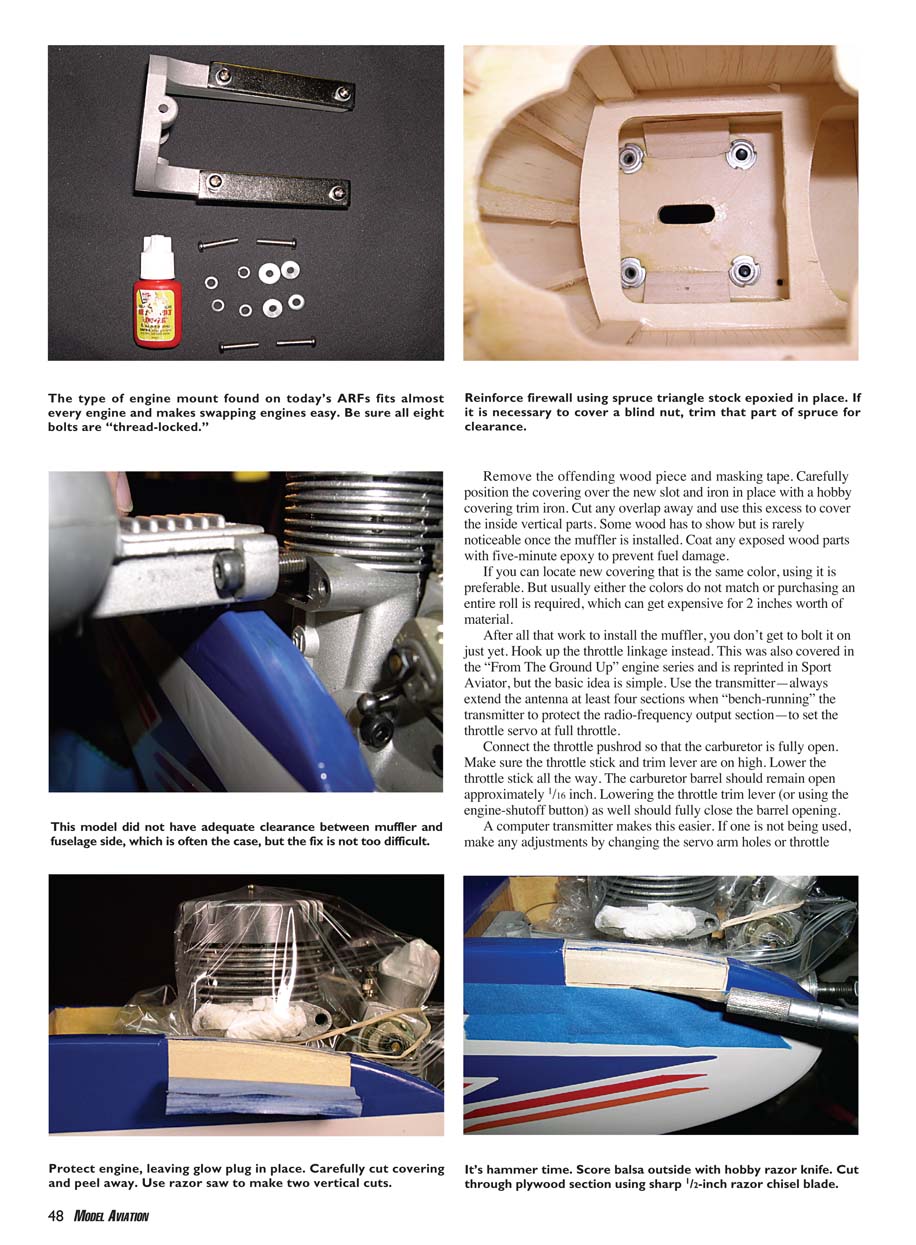
Many ARFs use the popular clamp-on mount. How to install an engine in this mount was covered in the "From the Ground Up" installments about engines. (If you do not have this article, it has been reprinted in Sport Aviator's Pri-Fly section at www.masportaaviator.com.)
The basic idea is to center the engine in the mount and position the rear of the engine's bolt plates firmly against the two rear clamping bolts in the mount for proper alignment. If your ARF uses the reinforced fiberglass mount, adjustable or rigid, go to the previously mentioned area of Sport Aviator for mounting details.
Install the mount onto the firewall. Use the bolts and washers provided, but make sure to use removable thread-locking compound. The clamp-on mounts are strong and allow easy installation.
However, the mount's metal construction allows some engine vibration to be transmitted to its mounting bolts. Tighten them securely. Remove the two clamp plates and position the engine on the mount in roughly its final position.
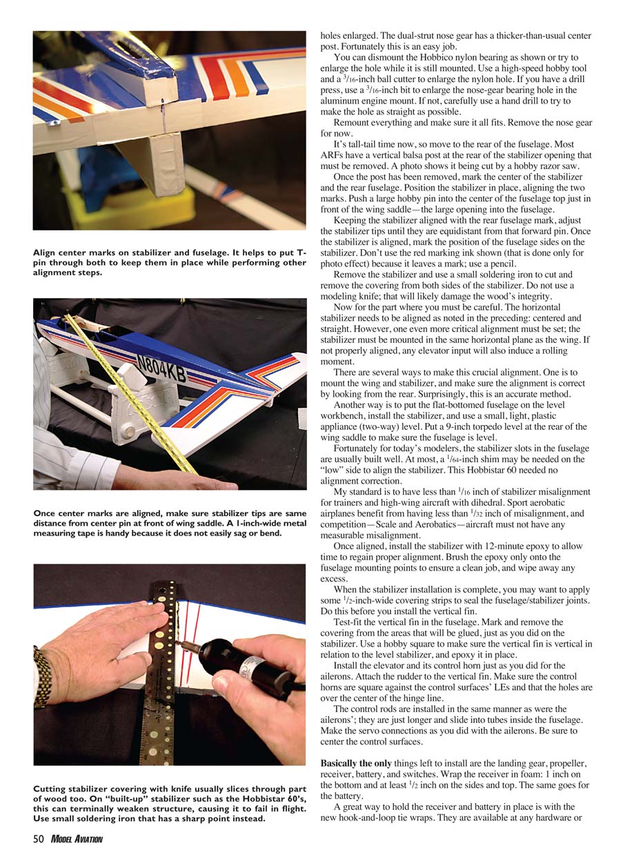
Get the muffler and see if the fuselage sides will permit its installation. If there is enough room, skip the following few paragraphs and go on to the section on setting up the throttle. Chances are there is insufficient muffler clearance; I don't know why, but many ARFs do not provide enough. Now what do we do?
Mount the engine in place. Plug the intake and exhaust holes, and cover the entire engine with a plastic bag. Use a straightedge and a sharp modeling razor knife to cut the covering. Make the cut slightly larger than required. Carefully peel back the covering and apply some low-tack painter's masking tape to protect the covering.
Use a razor saw to make the vertical cuts that are visible in the picture. Score the wood for the horizontal cut and then use a 1/2-inch hobby razor chisel to cut through the tough plywood. Nudge the other end of that chisel handle along with a tack hammer. You finally get to hammer away on something!
Remove the offending wood piece and masking tape. Carefully position the covering over the new slot and iron in place with a hobby covering trim iron. Cut any overlap away and use this excess to cover the inside vertical parts. Some wood has to show but is rarely noticeable once the muffler is installed. Coat any exposed wood parts with five-minute epoxy to prevent fuel damage.
If you can locate new covering that is the same color, using it is preferable. But usually either the colors do not match or purchasing an entire roll is required, which can get expensive for 2 inches worth of material.
After all that work to install the muffler, you don't get to bolt it on just yet. Hook up the throttle linkage instead. This was also covered in the "From The Ground Up" engine series and is reprinted in Sport Aviator, but the basic idea is simple. Use the transmitter—always extend the antenna at least four sections when "bench-running" the transmitter to protect the radio-frequency output section—to set the throttle servo at full throttle.
Connect the throttle pushrod so that the carburetor is fully open. Make sure the throttle stick and trim lever are on high. Lower the throttle stick all the way. The carburetor barrel should remain open approximately 1/16 inch. Lowering the throttle trim lever (or using the engine-shutoff button) as well should fully close the barrel opening.
A computer transmitter makes this easier. If one is not being used, make any adjustments by changing the servo arm holes or throttle trim. Whether you use a plastic pushrod or a rigid one, route the pushrod so the carburetor wheel or lever doesn't bind anywhere along the travel.
Once satisfied with the motion and travel, secure the pushrod end with a keeper or R-clip and secure the servo with its mounting screws. Check again for full open and full close. If the carburetor closes fully, remove the glow plug and plug the intake and exhaust as before and bench-run the engine to set the high- and low-speed needles. After tuning, reinstall the glow plug and run the engine in the model with the muffler installed to confirm clearance and alignment. The farther out from the servo arm’s center, the greater the amount of throttle movement. The farther out from the throttle arm’s center, the less the throttle moves.
Next you install the nose wheel. The Hobbistar 60 has a fairly strong nose-gear strut; many ARFs and RTFs do not. But even relatively strong nose-gear struts have a problem on grass runways.
Because of the need for a shock-absorbing spring, the actual strut—the part that extends downward to the axle and wheel—is offset from the center, usually by approximately 1/2 inch. That means every bump tries to turn the wheel off course. It is sometimes difficult for a new pilot, or any pilot for that matter, to keep the airplane’s takeoff roll in a straight line on bumpy grass.
Dual-strut nose gears are available that prevent this problem. Fults makes the one used in this installation (model RF400). The two struts are equidistant from the center post, ensuring that the bumps do not transmit a turning force.
The dual struts are also stronger and, although they do flex, can withstand harder landing forces without deforming than a single-strut nose gear can. Make sure the firewall has the extra bracing I discussed if you are going to use this stronger nose gear.
Although the Fults’ nose-gear kit includes mounting bearings, it is usually easier to modify the bearings that are premounted on your ARF. Using the Fults’ mounting bearings would require drilling new mounting holes in the firewall. That’s too much work for me. The Hobbistar’s mounting bearings only need to have their holes enlarged. The dual-strut nose gear has a thicker-than-usual center post. Fortunately this is an easy job.
You can dismount the Hobbico nylon bearing as shown or try to enlarge the hole while it is still mounted. Use a high-speed hobby tool and a 3/16-inch ball cutter to enlarge the nylon hole. If you have a drill press, use a 7/64-inch bit to enlarge the nose-gear bearing hole in the aluminum engine mount. If not, carefully use a hand drill to try to make the hole as straight as possible.
Remount everything and make sure it all fits. Remove the nose gear for now.
It’s tail-tail time now, so move to the rear of the fuselage. Most ARFs have a vertical balsa post at the rear of the stabilizer opening that must be removed. A photo shows it being cut by a hobby razor saw.
Once the post has been removed, mark the center of the stabilizer and the rear fuselage. Position the stabilizer in place, aligning the two marks. Push a large hobby pin into the center of the fuselage top just in front of the wing saddle—the large opening into the fuselage.
Keeping the stabilizer aligned with the rear fuselage mark, adjust the stabilizer tips until they are equidistant from that forward pin. Once the stabilizer is aligned, mark the position of the fuselage sides on the stabilizer. Don’t use the red marking ink shown (that is done only for photo effect) because it leaves a mark; use a pencil.
Remove the stabilizer and use a small soldering iron to cut and remove the covering from both sides of the stabilizer. Do not use a modeling knife; that will likely damage the wood’s integrity.
Now for the part where you must be careful. The horizontal stabilizer needs to be aligned as noted in the preceding: centered and straight. However, one even more critical alignment must be set: the stabilizer must be mounted in the same horizontal plane as the wing. If not properly aligned, any elevator input will also induce a rolling moment.
There are several ways to make this crucial alignment. One is to mount the wing and stabilizer, and make sure the alignment is correct by looking from the rear. Surprisingly, this is an accurate method.
Another way is to put the flat-bottomed fuselage on the level workbench, install the stabilizer, and use a small, light, plastic appliance (two-way) level. Put a 9-inch torpedo level at the rear of the wing saddle to make sure the fuselage is level.
Fortunately for today’s modelers, the stabilizer slots in the fuselage are usually built well. At most, a 1/64-inch shim may be needed on the “low” side to align the stabilizer. This Hobbistar 60 needed no alignment correction.
My standard is to have less than 1/16 inch of stabilizer misalignment for trainers and high-wing aircraft with dihedral. Sport aerobatic airplanes benefit from having less than 1/32 inch of misalignment, and competition—Scale and Aerobatics—aircraft must not have any measurable misalignment.
Once aligned, install the stabilizer with 12-minute epoxy to allow time to regain proper alignment. Brush the epoxy only onto the fuselage mounting points to ensure a clean job, and wipe away any excess.
When the stabilizer installation is complete, you may want to apply some 1/2-inch-wide covering strips to seal the fuselage/stabilizer joints. Do this before you install the vertical fin.
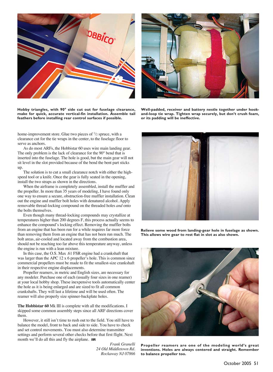
Test-fit the vertical fin into the fuselage. Mark and remove the covering from the areas that will be glued, just as you did on the stabilizer. Use a hobby square to make sure the vertical fin is vertical in relation to the level stabilizer, and epoxy it in place.
Install the elevator and its control horn just as you did for the ailerons. Attach the rudder to the vertical fin. Make sure the control horns are square against the control surfaces’ LEs and that the holes are over the center of the hinge line.
The control rods are installed in the same manner as were the ailerons; they are just longer and slide into tubes inside the fuselage. Make the servo connections as you did with the ailerons. Be sure to center the control surfaces.
Basically the only things left to install are the landing gear, propeller, receiver, battery, and switches. Wrap the receiver in foam: 1 inch on the bottom and at least 1/2 inch on the sides and top. The same goes for the battery.
A great way to hold the receiver and battery in place is with the new hook-and-loop tie wraps. They are available at any hardware or hobby store. Glue two pieces of 1/2 spruce, with a clearance cut for the tie wraps in the center, to the fuselage floor to serve as anchors.
As do most ARFs, the Hobbistar 60 uses wire main landing gear. The only problem is the lack of clearance for the 90° bend that is inserted into the fuselage. The hole is good, but the main gear will not sit level in the slot provided because of the bend—the bent part sticks up.
The solution is to cut a small clearance notch with either the high-speed tool or a knife. Once the gear is fully seated in the opening, install the two straps as shown in the directions.
When the airframe is completely assembled, install the muffler and the propeller. In more than 35 years of modeling, I have found only one way to ensure a secure, obstruction-free muffler installation. Clean out the engine and muffler bolt holes with denatured alcohol. Apply removable thread-locking compound on the threaded holes and onto the bolts themselves.
Even though many thread-locking compounds may crystallize at temperatures higher than 200 degrees F, this process actually seems to enhance the compound's locking effect. Removing the muffler bolts from an engine that has been run for a while requires far more force than removing them from an engine that has not been run much. The bolt areas, air-cooled and located away from the combustion area, should not be reaching too far above this temperature anyway, unless the engine is run with a lean mixture.
In this case, the O.S. Max .61 FSR engine had a crankshaft that was larger than the APC 12 x 6 propeller's hole. This is common since commercial propellers must be made to fit the smallest-size crankshaft in their respective engine displacements.
Propeller reamers, in metric and English sizes, are necessary for any modeler. Purchase one of each (usually four sizes in one reamer) at your local hobby shop. These inexpensive tools automatically center the hole as it is being enlarged and are sized to fit all common crankshafts. They will last a lifetime and will be used often. The reamer will also properly size spinner-backplate holes.
The Hobbistar 60 Mk III is complete with all the modifications. I skipped some common assembly steps since all ARF directions cover them.
However, it still isn't time to rush out to the field. You still have to balance the model, front to back and side to side. You have to check and set control movements. You must also determine transmitter settings and perform several other checks before that first flight. Next month we'll do all this and fly the airplane. MA
Frank Granelli 24 Old Middletown Rd. Rockaway NJ 07866
Frank Granelli
Transcribed from original scans by AI. Minor OCR errors may remain.

