
Grumman Ag-Cat
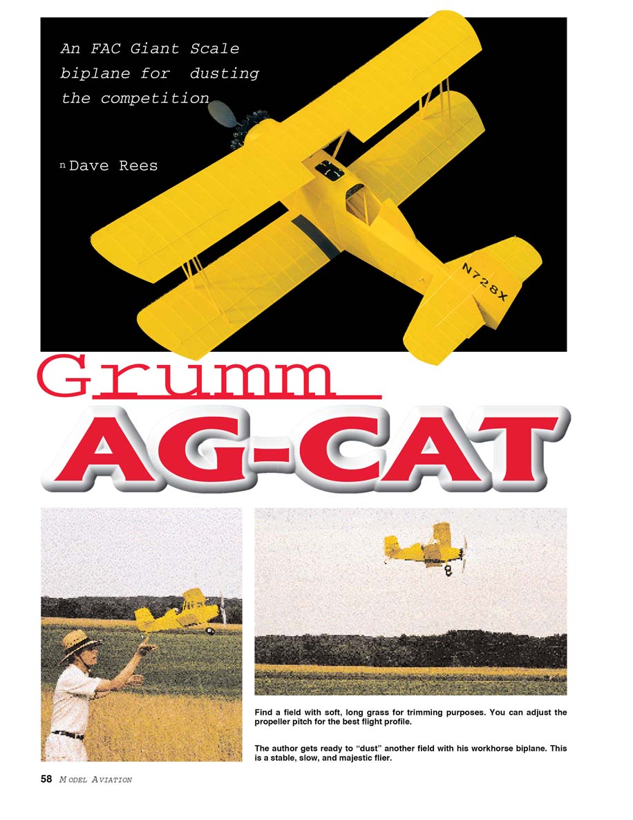
An FAC Giant Scale biplane for dusting the competition
Dave Rees
The Giant Scale event is relatively new in the Flying Aces Club (FAC) division. Not to be confused with radio-control Giant Scale, which is well-established, FAC rules state that the class is for rubber-powered scale models with wingspans of 42 inches or longer for monoplanes and 36 inches for biplanes. Nothing is more majestic than those large models floating over the field at the national meet in Geneseo, NY. However, I had dismissed the idea of making one after looking at our minivan and the amount of stuff we bring with us.
Even if taken apart, one Giant Scale model would take the space of three normal-size airplanes — that's three events I couldn't enter! (I usually fly in too many events.) I have been going through my Coconut Scale period the last few seasons, and now I am used to handling and transporting 36‑inch‑span models. So I thought, maybe if I pick the right biplane subject and use Coconut technology, I can still get everything in the minivan. The Ag‑Cat was the natural choice. If you can transport a 36‑inch‑span model, you can fly Giant Scale.
Crop‑spraying is popular in my home state of North Carolina. At work, nobody could resist leaving his or her computer and/or cubicle to look out the windows as a seemingly fearless pilot showered the field next to our parking lot. Nothing beats the sound of a big, chugging radial engine—it's quite a show!
When I began the research phase of this project, I learned that the Ag‑Cat was made near Geneseo, in Elmira, NY at the Schweizer glider factory. Several thousand Ag‑Cats were built there from the 1950s until the 1990s.
The idea for the airplane was conceived at the Grumman factory in Bethpage, Long Island, NY near the end of World War II, when the company began looking for peacetime airplanes to manufacture. The name Ag‑Cat was an extension of Grumman's famous "cat" series: Wildcat, Hellcat, Tigercat, etc. A decision was made not to manufacture the Ag‑Cat at Grumman facilities, and Schweizer was chosen as the subcontractor. Schweizer had made subcomponents for Grumman and had a good workforce of excellent airplane craftsmen.
The first model produced—the G‑164—was my choice for this project because it fits my image of how a spray plane should look. The open cockpit was enclosed when it was learned that the low‑pressure area created during flight drew in the sprayed materials, making the pilot look like a snowman! I like open cockpits. The G‑164 had the least bulk for the span of all the types, while presenting a reasonably long nose moment. One of the Coconut concepts is low wing loading, as achieved by minimum bulk. The Ag‑Cat is a simple airplane. It's all one color with few of the things judges like, such as guns, insignia, or panel lines. The scale score must be boosted by one thing: the engine. Fortunately, the 36‑inch‑span Ag‑Cat is almost one‑inch‑per‑foot scale; therefore the Williams Bros. Pratt & Whitney cylinder kits can be used to great advantage. You will spend a few evenings assembling all nine cylinders, but the result is a very convincing simulated radial that really adds to the model.
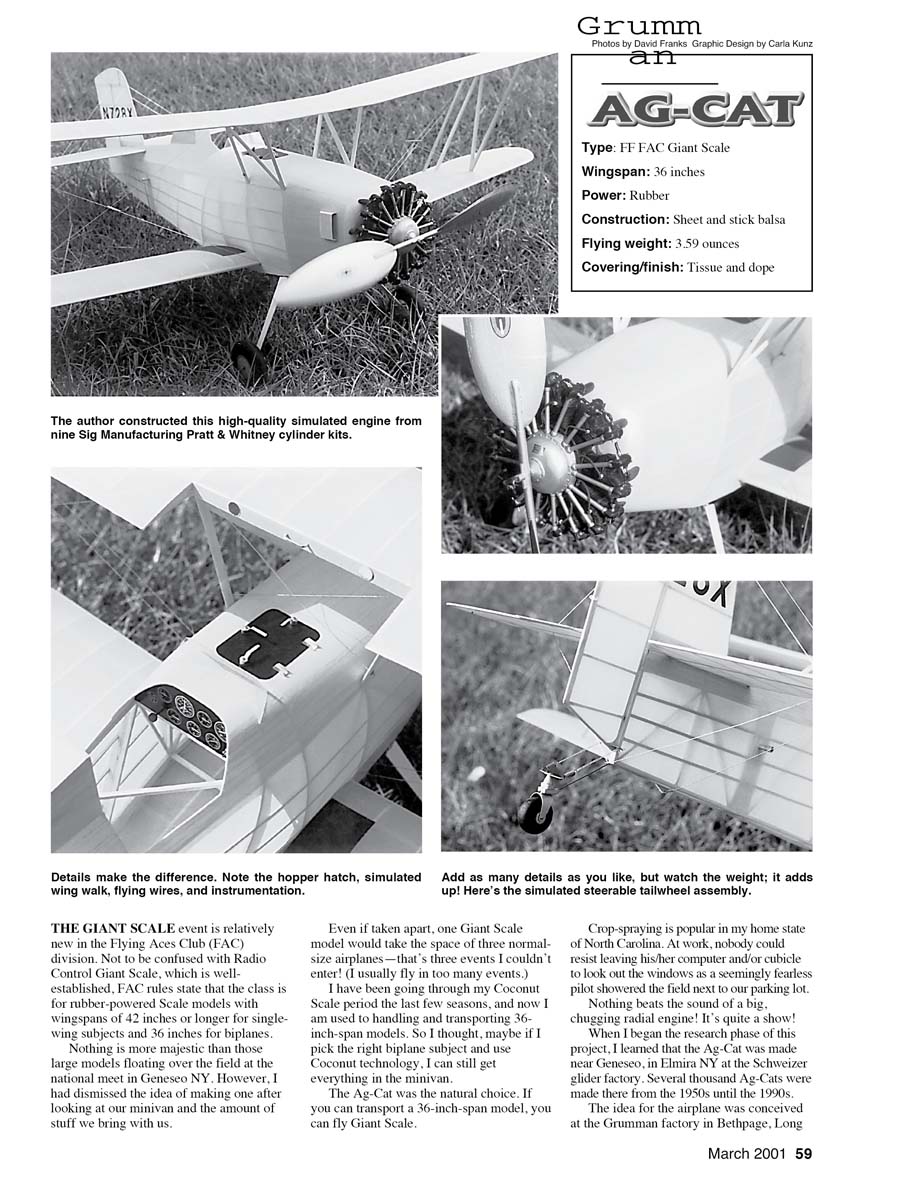
- Type: FF FAC Giant Scale
- Wingspan: 36 inches
- Power: Rubber
- Construction: Sheet and stick balsa
- Flying weight: 3.59 ounces
- Covering/finish: Tissue and dope
Add as many details as you like, but watch the weight; it adds up. Here’s the simulated steerable tailwheel assembly. The author constructed a high‑quality simulated engine from nine Sig/Williams Bros. Pratt & Whitney cylinder kits. Details make the difference. Note the hopper hatch, simulated wing walk, flying wires, and instrumentation.
CONSTRUCTION
Start with wood selection. Forget about precut sticks; they are too heavy. Choose the right sheets, then strip everything from them.
Not all structural members have the same stresses, so use the lighter wood in places where the loads are less. I weigh each sheet of wood I use, which really pays off in extra‑light structures.
The fuselage longerons take the most shock loads and torque from the motor when wound, so I use eight‑ to ten‑pound/cubic‑foot balsa for them. The cabane and interwing struts also need that weight.
Next in strength are the fuselage uprights/crossmembers and diagonals and wing leading and trailing edges; use six‑ to eight‑pound balsa. The tail members also fall in this category.
That's basically it—six‑ to ten‑pound is the range. The blocks at the nose area can be four‑ to six‑pound, but they are hard to find.
Here are some sheet weights for these grades:
- 1/16 x 3 x 36 — 10.5 grams, six pounds/cubic foot
- 3/32 x 3 x 36 — 21 grams, eight pounds/cubic foot
- 3/32 x 3 x 36 — 27 grams, ten pounds/cubic foot
- 1/8 x 3 x 36 — 28.5 grams, eight pounds/cubic foot
Be careful of nonhomogeneous sheets; they can be too hard in one place and too soft in another, but still give the correct overall weight. Look for nice, even sheets.
The full‑scale Ag‑Cat was made essentially like a model is constructed, so building up the parts won't present any challenges.
Fuselage Build the sides, one on top of the other, using Ambroid cement as an adhesive. It's plenty strong for a model this size.
The fuselage has each bay stiffened with diagonals, so it will not buckle under the torque of a fully wound motor.
I have added a hard point where you will launch the airplane. Launching with a fully wound motor can be tricky on a breezy day, and I find myself scrunching the fuselage. A little reinforcement is worth the weight penalty.
The formers and stringers on the sides and bottom, along with the 1/32‑inch sheet areas on top, complete the fuselage structure.
Assemble a box of light 3/8 and 1/2 sheets, as shown in dotted lines on the section view. Use white glue for added strength and toughness under impact.
Shape the outside and sand smooth, then hollow to a 3/32‑inch wall from the inside. I use a very sharp gouge for this operation, which results in a surprisingly light structure.
I noted many of these component weights on the plan when I remembered to weigh the items.
Notice the slight downthrust angle so the final downthrust won't look so bad. Cement the whole box to the front of the fuselage frame with white glue.
Landing gear on the Ag‑Cat is a modeler's dream—no extra braces! Bend up the .047‑inch wire over the plan. The sandwich former is an important structural member in an airplane this size, so proceed carefully.
Position the two former halves, then squeeze them in a vise to make dents for the wire. Score them slightly deeper with the end of the same wire.
Saturate the halves with ZAP cement, and quickly squeeze in the vise until cured. No gaps, please. This will stay on the wire, but you must mount it firmly.
Remove the 3/32 cross‑stick where the gear fits in the fuselage, and cement the sandwich in its place. Add the big gussets to transfer the loads to the wing saddle.
Cement scraps of 1/20 sheet to the wire legs, and cover with copy paper and white glue. This will absorb a great deal of abuse and not split off.
Engine
Purchase nine packs of #20300 or WB‑203 engine cylinder kits for Pratt & Whitney from Sig Manufacturing. They cost approximately $3 each.
Each pack comes with a small pattern for making the crankcase, which I made from balsa. The rubber runs through the case in our model, so make it with a one‑inch‑diameter hole in the center. Make the case with the grain running axially so it won't crush, and face it with 1/32 plywood cemented with ZAP to prevent splitting.
Now you can begin assembling the cylinders. I moved the ignition‑harness assembly behind the pushrods and omitted the intake manifolds to save weight. These would get knocked off easily during flight anyway.
The cement is critical. I used a styrene solvent from Plastruct, available from HO train stores. It leaves no residue and fuses the parts together so they're like a one‑piece molding.
Cement each cylinder to the crankcase with ZAP. The center part of the crankcase is also the removable nose plug, which you can make normally using the grain running axially.
The quality of the engine is very good when it's completed.
I like balsa wheels because they're lighter, but try Dave Brown's Lite Flite two‑inch‑diameter wheels if you live in an area where there is not much grass. The weight penalty is small, but you will have to bush the holes to fit the wire.
Wings
There are many wings to be built; fortunately, all ribs are alike.
I start by making an accurate template of the wing cross‑section from aluminum roofing flashing. The template can be laid on a six‑ to eight‑pound piece of 1/16 sheet, and the ribs can be sliced off quickly. There are 58 ribs, so the method must be fast.
Select and strip all the sticks for leading edges (LE), trailing edges (TE), and spars from eight‑pound wood, making sure there are no hard spots or tendencies to bow; those are sure ways to produce warps.
I design wings made in one piece rather than glued on each side of the fuselage. This removes all mismatch, and the wings are much stronger when covered through the center section.
Pin down the LE and TE using a straightedge, to avoid scallops. Glue in the lower ribs from 1/16‑inch square balsa. Notice that the lower wing has two pieces of 1/16 x 1/8 where the wing saddles fit.
While all this is drying, bend up the 1/32 x 1/16 bamboo wingtips over a hot soldering iron. They are tricky to bend, because they must match the upper rib curvature as well as the plan view. Cement the wingtips to the LE and TE with ZAP. Lay in the 1/16 sheet spars and glue them to the ribs.
Put in the 1/20 sheet diagonals and make sure to glue them to the lower ribs and to the two spars. Cut several strips 1/16‑inch wide; when cut to length, trim off a little height so each piece will fit against the rear spar. These diagonals stiffen the wings—particularly in torsion.
Slice off the upper ribs from 1/16 sheet, and cement them all in place.
Propeller
This is a very important part of the Ag‑Cat’s performance. If you feel the adjustable one I used is too complex, use one of the 11‑ or 12‑inch‑diameter plastic versions.
I am a confirmed “tweaker”; nothing bothers me more than not being able to adjust things in the endless search for better performance.
The adjustable‑pitch propeller will allow settings to suit the flying weather. For a calm day, set the pitch high and the motor seems to take forever to unwind. On a breezy day, lower the pitch until it penetrates the wind.
You must get into the habit of inspecting the propeller before launching, to make sure it has not changed from the previous flight and landing.
The blade dowels are moistened and inserted into the tube at the start of the flying session. They hold well for a day or two. If you find a setting you think works best, glue it with CyA. However, you will lose the ability to change a broken blade at the field.
I always make a duplicate set of blades in case one is broken. To make a set, cut a piece of 1/32 plywood and a piece of 10‑pound/cubic‑foot balsa for each blade. Soak the pieces in water and wrap them around a glass gallon jug at 15°, using strips of cloth to hold them in place.
Put the whole thing in the oven at 250°F for an hour, and let it cool slowly.
Remove the blades, and cement the balsa ones on top of the plywood ones with ZAP. The balsa provides a softer medium to sand to an airfoil curvature. Plane and sand all the blades until they look good, then glue the 5/32 dowels into the slots with CyA.
Wrap the blade with five‑ounce/square‑yard fiberglass to strengthen it for roughly the inner two inches; this is where they break.
Paint the blades with clear dope several times to obtain a good finish, then spray on a coat of silver. The dowels will be too tight in the hub tubes at first, so scrape and sand until you achieve a snug fit.
You may notice that I am a bobbin person; if you are an S‑hook or crocket‑hook type, feel free to use what works best for you. The same goes for latch‑type freewheelers.
Covering
My philosophy is low‑shrink; that says it all. It allows you to build light structures that don’t need to be strong enough to withstand the shrinking tissue.
The airplane also lasts longer before succumbing to warps—particularly in the tail parts. This is important—it's where all your adjustments are made. You can’t tolerate changes here.
Start by covering the tail. It is almost flat, so you can do a good job of pulling the tissue taut. I ask you not to shrink the tissue—do the best job you can.
Slit through the tissue for the aluminum hinges, and install them in one side of the stabilizer and rudder with CyA. Before installing, make sure the aluminum’s grain is lengthwise (the hinges will break if it’s crosswise). Set the tail aside for painting.
These were the easiest wings to cover I have seen in a while. There won't be any wrinkles the way the tips are made.
When both wings are covered, shrink the tissue with alcohol until it's taut. The structure is torsionally resistant enough to withstand the shrink forces.
The fuselage has no flat surfaces, so it will keep you busy and demonstrate your covering prowess. Pay particular attention around the saddle for the lower wings. Attach the tissue roughly 1/8‑inch all around the wing cutout—kind of a quirky contour. The fuselage also gets the alcohol shrink treatment.
Anyone who has flown FAC events for a while knows that tissue coloring fades under ultraviolet light. In time, it loses the brilliance so necessary for a good score from the judges. I know the rules state that painted and tissue colors are supposed to get the same points, but the brilliance factor is intangible.
For some time, I have used an overcoat of colored dope to make the tissue colors more brilliant and durable. Colored dope is effectively the same thing as clear dope plus pigment—just spray on an even coat.
Control the shrinkage with a plasticizer such as TCP, or distortion will result. I set a weight target so I don't get out of control with the amount of spraying I do. Six or seven grams are all I allow on an airplane this size.
Final assembly
As with all biplanes, getting the wings on right is the hard part. Here's one way to do it.
The painted lower wing should slip into the hole for it in the wing saddle. If it doesn't, trim the opening carefully until it fits snugly. Check for perfect alignment in all directions; then cement fast with white glue.
While this is drying, make two wing‑alignment fixtures from 1/2‑inch‑thick blue foam. Copy the wing positions from the plan side view, and make a cutout for each wing. The wing struts should have been made and painted matching the plan.
Slit the tissue at the wing‑attachment points and slide the struts in place. Make the same slits on the underside of the upper wing, and push the wing onto the struts.
If things line up well, try the cabane struts for fit. I used the foam fixtures near the fuselage to help keep the wings parallel from the front view. This is a careful process—don't rush things.
When you are satisfied, squirt CyA in each joint and it's together forever. Notice how strong the wings become when they are joined and braced like this. Light wings can be strong enough in a biplane!
The tail is the easy part. Cut the respective slots, and cement fast with white glue when the alignment is good. Note that the rudder attaches to the center of the elevator.
CyA the hinges in the elevators and rudder so all is permanent.
That's the sequence.
Details are the part I like best. Each modeler can add as much as he or she wants. Buy one of the reference books, because there is a limit to how much can be shown on a plan.
FLYING
Use the rubber sizes listed on the plan if you have controlled the weight as you built the model, and the flying weight is close to the total shown.
As weight goes up, the motor can be shortened to produce more power; however, adding more rubber could overload the carefully designed structure. Proceed with caution.
You need a "soft" field—grass or high weeds—until the Ag‑Cat is flying safely, even if it means driving some distance. You have spent a great deal of time on this project, so don't lose it during trimming. The Ag‑Cat flies very slowly, which makes trimming much smoother.
With a slightly taut motor, balance the airplane with your fingers. Your fingers should be close to the airplane's CG position, at least to start out. Ballast as needed. Crank in 300 turns, and see how it flies at a medium‑pitch position on the propeller.
Adjust flying surfaces as required. Slowly increase the winds while correcting bad characteristics.
As the Ag‑Cat climbs high enough, notice what happens in the glide phase of the flight. Fine‑tune the adjustments to optimize the glide. My Ag‑Cat climbs out at a steep angle, but slowly, which really looks strange!
Try adjusting the propeller pitch last, until you see which pitch works best and gives the longest flight.
When adjusting the propeller, make sure the blades are not twisted off the dowels. The dowels really stay put in the hub. I grab the dowels with a smooth‑jawed pair of pliers to turn them, rather than risk putting the load on the blades.
I am sure you will like this big, slow‑flying Ag‑Cat.
MA
Dave Rees 606 Walnut Creek Dr. Goldsboro, NC 27534
Transcribed from original scans by AI. Minor OCR errors may remain.

