
GRUMMAN F-4F Wildcat
by Jim Ryan
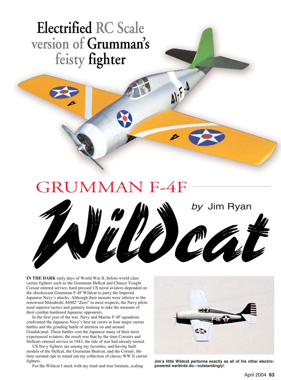
In the dark early days of World War II, before world-class carrier fighters such as the Grumman Hellcat and Chance Vought Corsair entered service, hard-pressed US naval aviators depended on the obsolescent Grumman F4F Wildcat to parry the Imperial Japanese Navy’s attacks. Although their mounts were inferior to the renowned Mitsubishi A6M2 “Zero” in most respects, Navy pilots used superior tactics and gunnery training to take the measure of their combat-hardened Japanese opponents.
In the first year of the war, Navy and Marine Wildcat squadrons confronted the Japanese Navy’s best air crews in four major carrier battles and the grinding battle of attrition on and around Guadalcanal. These battles cost the Japanese many of their most experienced aviators; by the time Corsairs and Hellcats entered service in 1943, the tide of war had already turned.
US Navy fighters are among my favorites, and having built models of the Hellcat, the Grumman Bearcat, and the Corsair, the time seemed ripe to round out my collection of classic WWII carrier fighters. For the Wildcat I stuck with my tried-and-true formula, scaling the airframe to 170 square inches of wing area and aiming for an all-up weight of 18 ounces. At this size the F4F has a proportionally fatter fuselage than any of my efforts to date, so weight control is crucial. With the F4F’s midwing configuration, I also had to pay special attention to the structure around the wing saddle. Given the fuselage’s shape, my favored practice of crutch-built construction worked especially well. The Wildcat has lived up to all my expectations and is one of my favorite models, so let’s get started!
CONSTRUCTION
The airframe was designed with AutoCAD. The fuselage is a conventional structure using formers, stringers, and balsa-sheet construction, and the wing is foam-sheeted with balsa. The weight goal for the finished empty airframe is 7 ounces. I use regular thin cyanoacrylate glue for nearly all construction and odorless cyanoacrylate for the foam wing.
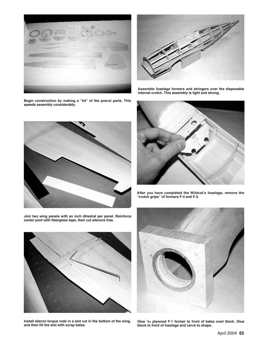
I suggest that you start with a “kit” by precutting all major parts to shape. You can accomplish this in one or two evenings, and construction will go much more quickly. I transfer the part templates to the sheet wood with the acetone transfer method, which is quick and easy to do. (I'm offering a parts pack including the foam wing cores and a vacuum-formed canopy. Send $24, including shipping, to me at the address at the end of this article.)
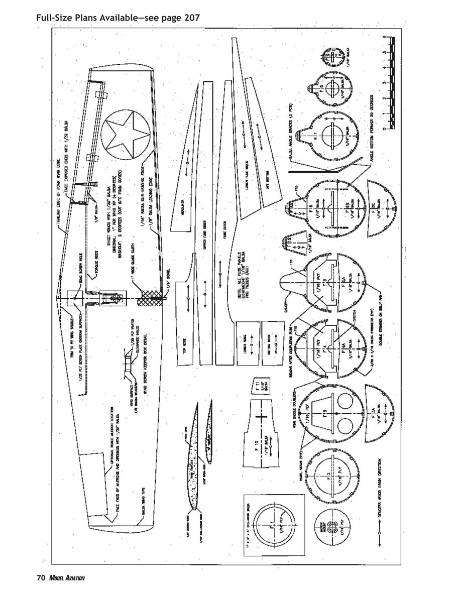
Wing
- Lightly sand the foam cores and clean them off with a Shop-Vac or tack rag.
- Install the 1/16-inch sub-leading edges (LEs) with thick odorless cyanoacrylate and trim flush.
- Glue the wing skins from 1/32 balsa and block-sand them smooth. After sanding and dusting, attach the skins with your favorite epoxy or contact adhesive. Note: 3M Super 77 contact adhesive contains acetone and is unsuitable for use on foam wing cores.
- Trim the wing skins flush with the sub-LEs, then install the 1/8-inch LE caps. Trim roots and tips flush with the cores and then trim the trailing edges (TEs) as shown on the plans.
- Install the 1/2-inch balsa wingtips and carve them to shape.
- Cut the ailerons from the wing panels as shown on the plan view. Apply 1/16 balsa strips to the exposed TE. Trim 1/4 inch from the LEs of the ailerons and install 1/8-inch balsa LEs. You can trim the ailerons shorter and face their ends with 1/32 balsa.
- Before joining panels, bevel the roots to the proper angle: align the root with the workbench edge and block up the wingtip an inch, then use a sanding block to bevel. Repeat for the other panel.
- Join the wing panels with an inch dihedral per panel. With each wingtip blocked up an inch, join the panels with thick odorless cyanoacrylate or epoxy.
- Reinforce the center joint with 1.5-ounce fiberglass tape applied with thin odorless cyanoacrylate.
- Install the aileron torque rods fabricated from 1/16-inch music wire and 3/32-inch brass tubing. The torque rods mate with the ailerons at the very end, forming the inboard hinge. The easiest installation is to cut through the bottom sheeting, remove the underlying foam, mount the rods with thick odorless cyanoacrylate, and avoid getting glue inside the brass tubing. Fill the slot with 1/8 balsa and block-sand flush.
- Cut hinge slots and dry-mount the ailerons. Install the 1/16-inch plywood aileron servo mount after finishing the wing.
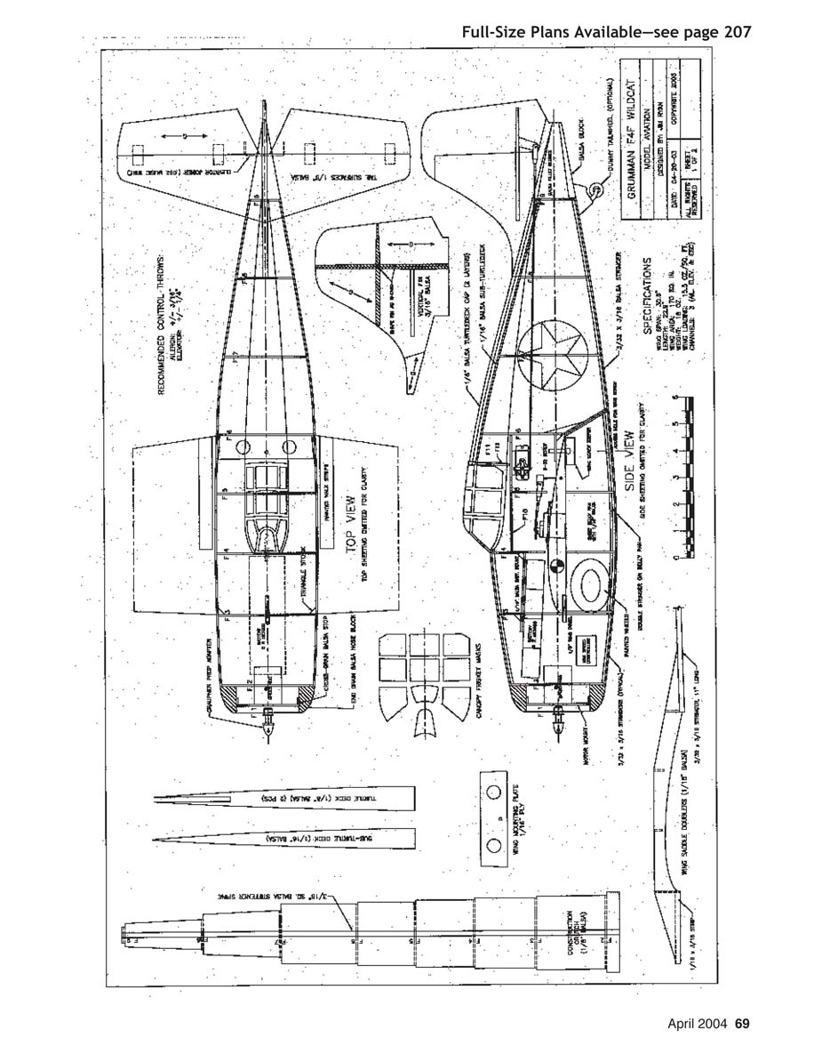
Fuselage
The fuselage is built over a disposable crutch that is indexed for each former location. Before beginning, glue a 3/16-inch square hard-balsa spine down the center of the crutch to make it more rigid. Ensure the crutch is flat and straight. Do not glue any formers to the crutch; the crutch is removed when the fuselage is complete.
- Assemble F-6, F-6-A, and F-6-B, beveling and joining them at the proper 30° angle to allow removal of the wing.
- Glue reinforcement strips and extension stringers onto the wing-saddle doublers. Note the partial cutouts in the "crutch grips" of F-4 and F-5; these sections will be removed after fuselage completion.
- Slide each former over the crutch into its indexed position. Keep F-2 square to the crutch; this former determines the motor's thrustline.
- Dry-fit the 3/32 x 3/16 stringers and wing-saddle doubler assemblies. After ensuring each former is perpendicular to the crutch, glue the stringers to the formers with thin cyanoacrylate. The stringers that are part of the wing-saddle assembly extend past F-9 by approximately two inches.
- Assemble F-10, F-11, and F-12 cockpit formers and glue them in place on F-4, F-5, and F-6. Glue the F-13 sub-turtledeck in place atop F-12, F-6, F-7, and F-8. The pointed rear tip of the turtledeck seats between the top two stringers just ahead of F-9.
- Glue the lower edge of the fuselage side panels to the side stringers with thin cyanoacrylate. Install each pair of panels simultaneously to avoid induced stresses. Make sure side panels overlap exactly half of the side stringers; a light pencil mark at each former center helps.
- If necessary, dampen fuselage panels to help bending, then carefully push them into place and glue. Glue the upper fuselage panels edge to edge with the fuselage sides, starting at the middle and working toward the ends. Add the rest of the fuselage panels.
- Once panels are in place, glue the bottom tail block and carve it to shape. Plane or block-sand the turtledeck panels flush with the subturtledeck and add the turtledeck cap laminated from two layers of 1/8 balsa.
- Remove the construction crutch. Cut away the crutch grips from F-4 and F-5 by cutting through the remaining tabs. The main fuselage structure is now complete.
Wing Installation
- Block-sand the wing's LE at the root so it will have a flat face against F-3 and trim the TE at the root to fit into the wing saddle.
- Tap the 1/16 plywood wing mount for a 6-32 nylon screw, glue the mount in place in the fuselage, and reinforce the joint with 1/4 balsa triangle stock.
- Drill the screw hole through the wing and install the 6-32 nylon wing screw.
- Square the wing with the tail of the fuselage, pinning it in the proper position. Drill the wing's LE to accept the 1/8-inch locator dowel.
Cowl Block
The cowl is a block of end-grain balsa carved to shape. The block is bored for the motor opening. Draw datum lines on the front of the block to guide installing F-1, which serves as a sanding guide. Glue the block in place onto F-2 and carve and sand to final shape. I recommend waiting until the model is covered to install the 1/16 plywood motor mount.
Empennage
- Make the vertical fin from 3/16 balsa for necessary stabilizer-mount strength. Block-sand the fin to taper from 3/16 inch at the stabilizer slot to 1/8 inch or less at the tip, and sand it to a symmetrical airfoil section.
- Cut stabilizer and elevator halves from 1/8 sheet stock. Trial-fit the empennage assembly to the fuselage.
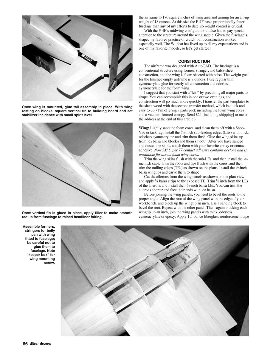
- Glue the vertical fin to the fuselage, pinning it so it's 90° to the wing and aligned with the fuselage axis.
- Glue tail fillet blocks (from 1/4 balsa stock) in place on either side of the vertical fin but do not glue them to the fin at this time. Remove the vertical fin and replace it with a spacer made from scrap 3/16 balsa.
- Carve and sand the turtledeck cap and tail fillets to shape. Remove spacers and slip the vertical fin back into place, again ensuring it is 90° to the wing.
- Dry-fit the stabilizer and check that it's at 0° incidence relative to the bottom of the wing. When satisfied, glue the vertical fin in place with thin cyanoacrylate, but leave the stabilizer loose for the moment.
- Cut elevator hinge slots and test-fit them. Install the music-wire elevator joiner (or a 1/8-inch-diameter dowel joiner). I found it easiest to permanently install the stabilizer after covering.
Belly Pan
- With the wing mounted, install the belly-pan formers on the bottom of the wing, being careful not to glue them to the fuselage.
- Dry-fit the three belly-pan stringers. The center stringer is laminated from two layers of 3/32 x 3/16 balsa.
- You may want to add a "keeper box" to hold the wing screw in place in the wing.
- Remove the wing from the fuselage, leaving the screw in place in the wing, and install 1/16-inch belly-pan sheeting. Trim and block-sand front and rear edges flush with the formers.
- Drill a 1/8-inch access hole over the wing hold-down screw and reinstall the wing. Sand the joint between the belly pan and fuselage sheeting flush, being careful not to sand through the sheeting.
Last Details
- Install servo mounts with thin cyanoacrylate.
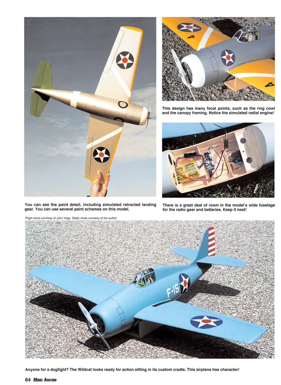
- Cut the battery mounting plate from 1/16 balsa and install it on F-3 and F-4, using 1/4 triangle stock to reinforce joints. Apply a strip of Velcro to the mounting plate to secure the battery pack.
- Use .038 music wire for pushrods to keep weight to a minimum. On a model this small, I prefer control horns from 1/32 plywood mortised into the surfaces for added strength.
Finishing
The Wildcat is suitable for film covering, but I prefer fiberglass and paint. Tissue and dope also work well. I covered the prototype with 1/32-inch fiberglass cloth and painted it with model enamel. It's a replica of the F4F-3 that Lieutenant "Butch" O'Hare flew when he earned the Medal of Honor on February 20, 1942.
You can paint the canopy framing easily using the frisket masks shown on the plans. Protect the canopy's inside surface with masking tape to prevent overspray. After painting the framing, remove the masks and glue the canopy in place with Formula 560 or equivalent canopy glue. Install the hardware, and you're ready to go.
Flight Testing
- Be careful checking the center of gravity (CG). I suggest starting with the CG two inches behind the LE of the wing where it exits the fuselage, then adjust to suit your tastes. If you keep the weight near 18 ounces, the Wildcat should fly well.
- Get a capable assistant to hand-launch the model on the first flights. It needs to be thrown straight and level. If the launcher loses it upward, it's likely to stall. Hold the wings level and begin a shallow climb.
- Landings are made with a straight-in approach; hold the model just off the ground until it settles in. With the washout in the wing, the Wildcat has forgiving stall characteristics.
I've been extremely pleased with this model's aerobatic performance. I use electric power for my warbirds and most of my flying is with a Speed 400 motor and eight HE1000 NiMH cells; endurance is in the seven- to nine-minute range. The Wildcat will do huge loops and Cuban 8s, and the roll rate is surprisingly fast. Inverted flight is solid. The Wildcat really is a joy to fly.
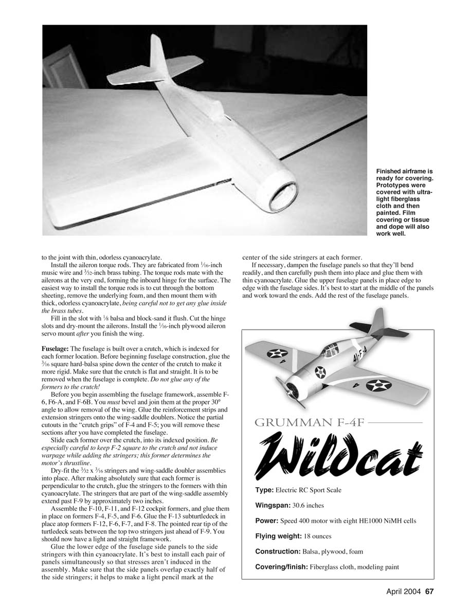
SPECIFICATIONS
- Type: Electric RC Sport Scale
- Wingspan: 30.6 inches
- Power: Speed 400 motor with eight HE1000 NiMH cells
- Flying weight: 18 ounces
- Construction: Balsa, plywood, foam
- Covering/finish: Fiberglass cloth, modeling paint
Jim Ryan 6941 Rob Vern Dr. Cincinnati, OH 45239 [email protected]
Transcribed from original scans by AI. Minor OCR errors may remain.

