
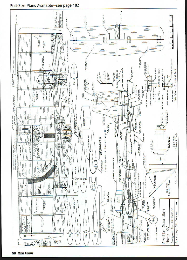
Guardian
Bill Melton
Profile
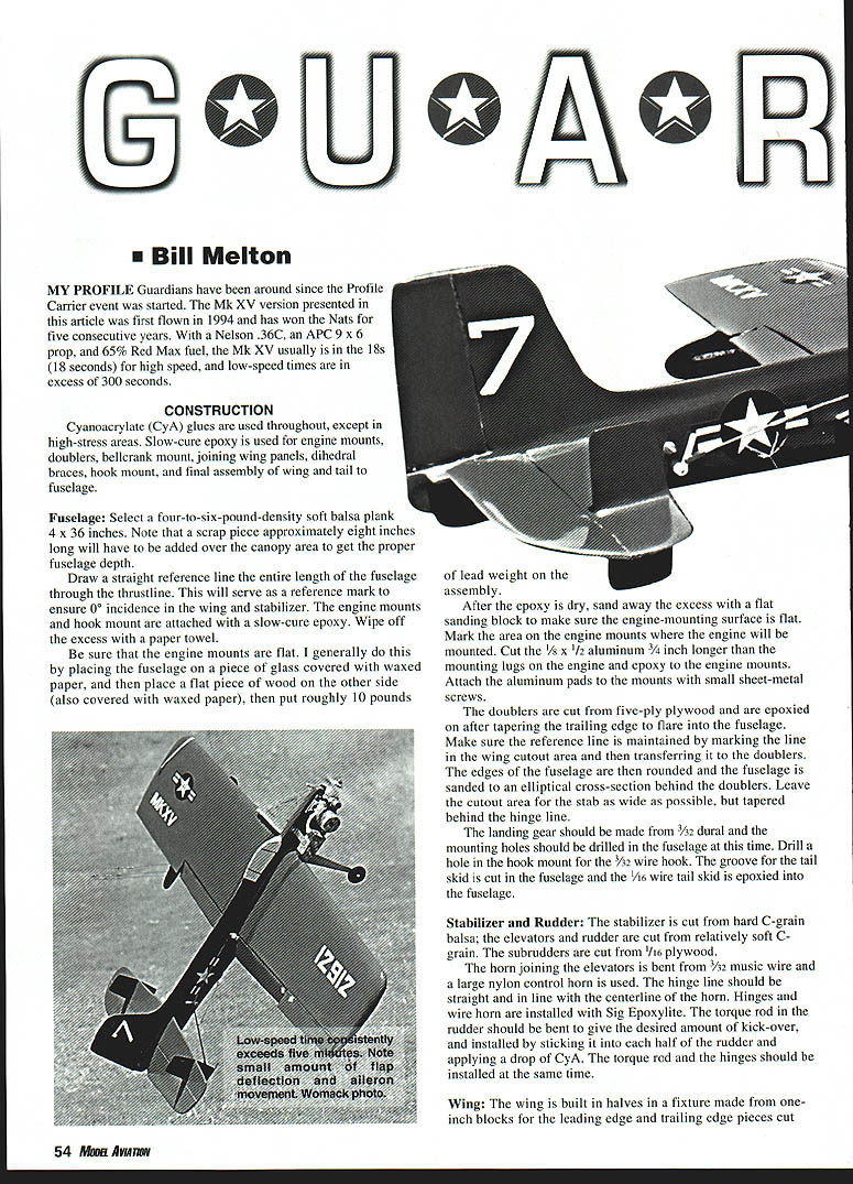
Guardians have been around since the Profile Carrier event was started. The Mk XV version presented in this article was first flown in 1994 and has won the Nats for five consecutive years. With a Nelson .36C, an APC 9 x 6 prop, and 65% Red Max fuel, the Mk XV usually is in the 18s (18 seconds) for high speed, and low-speed times are in excess of 300 seconds.
Construction
Cyanoacrylate (CyA) glues are used throughout, except in high-stress areas. Slow-cure epoxy is used for engine mounts, doublers, bellcrank mount, joining wing panels, dihedral braces, hook mount, and final assembly of wing and tail to fuselage.
Fuselage
- Select a four-to-six-pound-density soft balsa plank 4 x 36 inches. Note that a scrap piece approximately eight inches long will have to be added over the canopy area to get the proper fuselage depth.
- Draw a straight reference line the entire length of the fuselage through the thrustline. This will serve as a reference mark to ensure 0° incidence in the wing and stabilizer.
- The engine mounts and hook mount are attached with slow-cure epoxy. Wipe off the excess with a paper towel.
- Ensure the engine mounts are flat. One method is to place the fuselage on a piece of glass covered with waxed paper, place a flat piece of wood on the other side (also covered with waxed paper), then put roughly 10 pounds of lead weight on the assembly.
- After the epoxy is dry, sand away the excess with a flat sanding block to make sure the engine-mounting surface is flat.
- Mark the area on the engine mounts where the engine will be mounted. Cut the 1/8 x 1/2 aluminum 3/4 inch longer than the mounting lugs on the engine and epoxy to the engine mounts. Attach the aluminum pads to the mounts with small sheet-metal screws.
- The doublers are cut from five-ply plywood and are epoxied on after tapering the trailing edge to flare into the fuselage. Make sure the reference line is maintained by marking the line in the wing cutout area and then transferring it to the doublers.
- Round the edges of the fuselage and sand to an elliptical cross-section behind the doublers. Leave the cutout area for the stab as wide as possible, but tapered behind the hinge line.
- The landing gear should be made from 3/32 dural and the mounting holes should be drilled in the fuselage at this time.
- Drill a hole in the hook mount for the 3/32 wire hook. Cut the groove for the tail skid in the fuselage and epoxy the 1/16 wire tail skid into the fuselage.
Stabilizer and Rudder
- The stabilizer is cut from hard C-grain balsa; the elevators and rudder are cut from relatively soft C-grain. The subrudders are cut from 1/16 plywood.
- The horn joining the elevators is bent from 3/32 music wire and a large nylon control horn is used. The hinge line should be straight and in line with the centerline of the horn. Hinges and wire horn are installed with Sig Epoxylite.
- The torque rod in the rudder should be bent to give the desired amount of kick-over, and installed by sticking it into each half of the rudder and applying a drop of CyA. The torque rod and the hinges should be installed at the same time.
Wing
- The wing is built in halves in a fixture made from one-inch blocks for the leading edge and trailing edge pieces cut from a 3/8 balsa plank that is one inch tall at the root and 1-1/8–1/16 inches tall at the tip, to give the correct amount of washout. The blocks are then pinned over the plans.
- The leading edges are pinned to the blocks on edge and the bottom trailing edge planking pinned to the trailing edge jig. Note: The cutouts in the trailing edge planking for the flaps are not made until later. The ribs are then glued in. The location of the spars is marked, notches are cut, and the top spars are glued in.
- The top planking on the trailing edge is now added. Normal glue (such as Testors B) is usually used here; it is very hard to get CyA to go where you want it with everything pinned down.
- Flip the wing panels upside down to put in the bottom spar. Note: The trailing edge fixture must be reversed so that the one-inch-tall part is now at the tip and the wide part is at the root. Install the bottom spars.
- Join the wing halves. Pin scrap-balsa blocks to the plans to get the 5/8–3/4-inch dihedral under each panel. Sand the leading edges, spars, and trailing edge planking so that they fit properly.
- Epoxy these parts together after making sure that the leading edge and the trailing edge are equal distance from the building board, and that the appropriate washout remains at the tips.
- Install the leading and trailing edge reinforcements and the spar doublers. Install the bellcrank platform with epoxy. Add the reinforcement between the bottom inboard spar and the bellcrank platform and the vertical webbing between the outboard spars and between the trailing edge planking pieces.
- Prepare the bellcrank (Brodak C-24) by deburring the holes for the .027 flexible leadout cables and redrilling the hole for the elevator pushrod as far in toward the pivot point as possible, to slow down the elevator movement.
- Bushing the leadouts: place 1/2-inch-long pieces of 1/32 brass tubing over the leadout wire, then bend in a U shape around round-nose pliers. Insert this into the hole in the bellcrank and finish bending to close the bushing. Wrap the ends of the cable with copper wire, solder, and wash with baking soda or a good degreaser to prevent rusting.
- Mark the location of the bellcrank on the bellcrank mount so that the angle of the sliding slot is approximately halfway between the position of the leadouts at high and low speed.
- If the slot is angled too much, there is friction in the bellcrank when going to low speed, and a tendency for the airplane to dive as the bellcrank is moved.
- If the slot is too shallow, the bellcrank binds at low speed and it is difficult to get small throttle movement.
- Lubricate all areas of the bellcrank with a dry lubricant.
- Mark and cut out the area in the bellcrank platform to clear the sliding portion. Cut holes or slots in the ribs to clear the leadouts.
- Use 3/8-inch squares of hard 1/32 aluminum as spacers between the bellcrank and the plywood platform, and 1/2-inch squares of the same material on the other side of the platform as washers to prevent the mounting bolts from pulling through the platform.
- Mount the bellcrank and make sure everything works freely. If it does not, fix it—do not allow any binding or friction in the bellcrank operation. Put in the 1/2 thick partial rib in the center section. Solder nuts on bellcrank mounting bolts. Plank the leading edges of the wing and the bottom portion of the center section.
- Install the throttle pushrod through a 5/16-inch wide slot in the lower planking. The pushrod is shaped to allow total bellcrank movement and to emerge through the slot in the bottom planking.
- The elevator pushrod is prepared by making a Z bend in the 1/16 wire and soldering a washer on the pushrod to raise it above the leadouts. There is planking between the #3 and #4 ribs on the lower surface of the outboard panel for the passage of the pushrods from the changeover bellcrank between the flap and the aileron.
- Install the rest of the castrips.
- The line slide is cut from 1/16 plywood. The moving part is cut from tin-can stock, with Perfect eyelets as leadout guides. When soldering the eyelets to the tin, angle the eyelets as they will be in the low-speed position. Use pieces of 1/32 plywood as spacers between the tin and the plywood slide holder.
- Cut a 1/16-inch wide slot in planking next to the #4 rib between the spar and the trailing edge planking, and install the line slide mechanism—first with CyA, then epoxy.
- Make the cutout in the bottom planking to clear the leadouts at the high- to low-speed positions. Note that the bottom spar will be cut and tapered to clear the leadouts in the high-speed position and that rib #3 may also be cut through.
Low-Speed Design Considerations
Scoring in Navy Carrier is heavily dependent on low-speed performance. Important features for good low-speed flight:
- Blunt leading edge of wing to soften stall tendencies
- Symmetrical airfoil, with a minimum thickness of 12% at the root and 14% at the tip
- 3/8–3/4 inch washout in each wing panel to minimize tip stall
- Low aspect ratio to maximize allowable line sweep
- Large outboard aileron to induce "banking"
- Two to four ounces of tip weight
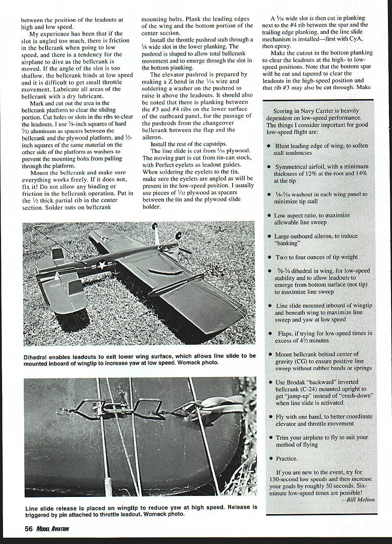
- 5/8–3/4 inch dihedral in wing for low-speed stability and to allow leadouts to emerge from bottom surface (not tip) to maximize line sweep
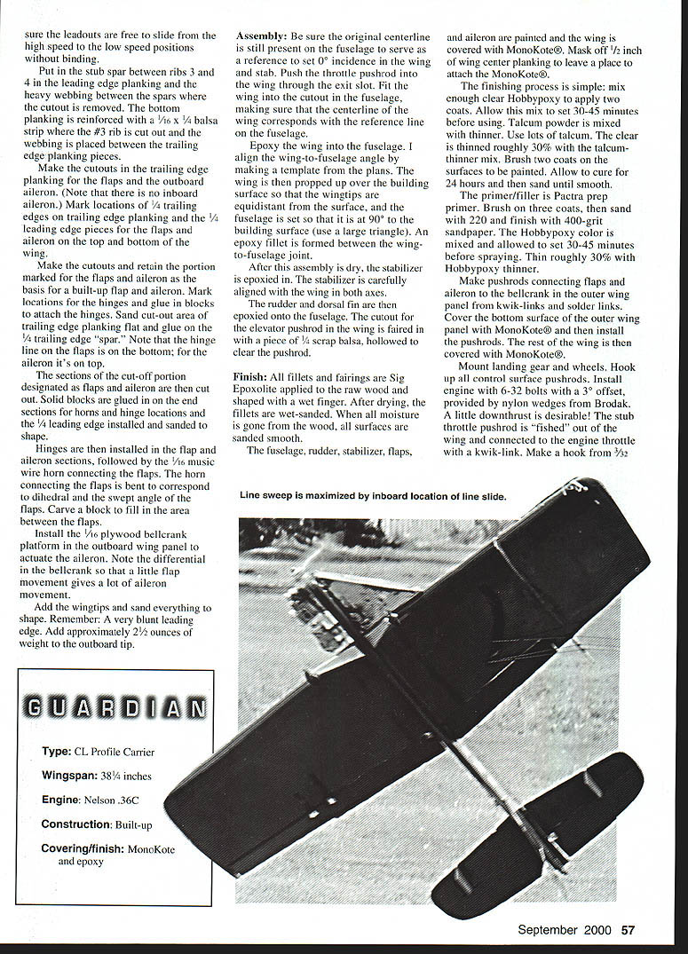
- Line slide mounted inboard of wingtip and beneath wing to maximize line sweep and yaw at low speed
- Flaps, if trying for low-speed times in excess of 4 1/2 minutes
- Mount bellcrank behind center of gravity (CG) to ensure positive line sweep without rubber bands or springs
- Use Brodak "backward" inverted bellcrank (C-24) mounted upright to get "jump-up" instead of "crash-down" when line slide is activated
- Fly with one hand to better coordinate elevator and throttle movement
- Trim your airplane to fly to suit your method of flying
- Practice
If you are new to the event, try for 150-second low speeds and then increase your goals by roughly 30 seconds. Six-minute low-speed times are possible!
—Bill Melton
Assembly
Be sure the original centerline is still present on the fuselage to serve as a reference to set 0° incidence in the wing and stab. Push the throttle pushrod into the wing through the exit slot. Fit the wing into the cutout in the fuselage, making sure that the centerline of the wing corresponds with the reference line on the fuselage.
Epoxy the wing into the fuselage. Align the wing-to-fuselage angle by making a template from the plans. Prop the wing up over the building surface so that the wingtips are equidistant from the surface, and set the fuselage so that it is at 90° to the building surface (use a large triangle). Form an epoxy fillet between the wing-to-fuselage joint.
After this assembly is dry, epoxy the stabilizer in. Carefully align the stabilizer with the wing in both axes.
Epoxy the rudder and dorsal fin onto the fuselage. Fair the cutout for the elevator pushrod in the wing with a piece of 1/4 scrap balsa, hollowed to clear the pushrod.
Finish
- Apply all fillets and fairings with Sig Expoxolite to the raw wood and shape with a wet finger. After drying, wet-sand the fillets. When all moisture is gone from the wood, sand all surfaces smooth.
- Paint the fuselage, rudder, stabilizer, flaps, and aileron; cover the wing with MonoKote®. Mask off 1/2 inch of wing center planking to leave a place to attach the MonoKote®.
- Mix enough clear hobbycoppers to apply two coats. Allow this mix to set 30–45 minutes before using. Mix talcum powder with thinner—use lots of talcum. Thin the clear roughly 30% with the talcum/thinner mix. Brush two coats on the surfaces to be painted. Allow to cure for 24 hours and then sand until smooth.
- Primer/filler is Pactra prep n primer. Brush on three coats, then sand with 220 and finish with 400-grit sandpaper.
- Mix Hobbypoxy color and allow to set 30–45 minutes before spraying. Thin roughly 30% with Hobbypoxy thinner.
- Make pushrods connecting flaps and aileron to the bellcrank in the outer wing panel from kwik-links and solder links. Cover the bottom surface of the outer wing panel with MonoKote® and then install the pushrods. Cover the rest of the wing with MonoKote®.
- Mount landing gear and wheels. Hook up all control surface pushrods.
- Install engine with 6-32 bolts with a 3° offset, provided by nylon wedges from Brodak. A little downthrust is desirable.
- Fish the stub throttle pushrod out of the wing and connect it to the engine throttle with a kwik-link. Make a hook from 3/32 and cover the wing root area with a 1/16 ply doubler.
Specifications
- Type: CL Profile Carrier
- Wingspan: 38-1/4 inches
- Engine: Nelson .36C
- Construction: Built-up
- Covering/finish: MonoKote and epoxy
Profile Guardian
Model by: Bill Melton Designed by: Bill Melton Drawn by: Bill Collins
(venturi is cut off just above the needle valve holes. The carb is filed square and held in place with JB Weld®.)
Trimming and Flying
This design has two annoying habits that often need to be removed by trimming.
- It may roll over on its back and loop into the ground. Possible causes:
- Airplane is tailheavy
- Flaps are dropped too much
- Line slide goes back too far
Remedies:
- Check center of gravity (CG), which should be 20–30% back from the wing leading edge.
- If CG adjustment does not work, check flap movement. Flaps should be lowered roughly 1/4 inch or 3/8 inch maximum.
- The line slide should not go past the trailing edge of the wing root. Too much line sweep or a line slide mounted too far inboard will also cause this roll-up reaction.
- Downthrust is a standard trim point that reduces roll-up and helps to prevent “stopping” at very low speeds.
- Tendency to change from the 60° nose-high attitude to level flight, or even into a dive, when going into the wind. Causes and remedies:
- Caused by a noseheavy condition or too much flap.
- Too little tip weight reduces line tension; too much tip weight causes hinging or “flopping” at low speed.
- Do not be afraid to temporarily hang weight out on the airplane and see what you like.
Flying is simple and straightforward. Every effort should be made to obtain a straight, level takeoff to a maximum 6–8 feet altitude. The transition to low speed will be accompanied by a “jump-up” when the line slide changes to the low-speed position. A “flick” of down elevator will drop the hook (use a rubber band for tension) and actuate the rudder, flaps, and aileron.
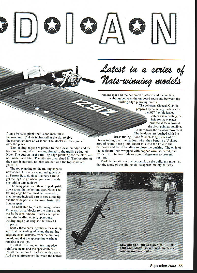
For initial flights, drop the flaps approximately 1/4 inch. On the downwind side of the circle, the airplane will tend to settle. A little up-elevator and a slight increase in throttle should result in a nose-high attitude.
Get someone in the circle with you with a 60° triangle so that you can learn where 60° really is! Remember, 60° is 2/3 of the way to vertical.
Another problem is that the airplane may stop forward motion or even back up when going into a wind. Downthrust in the engine helps, but the pilot must anticipate this tendency.
Landings are generally made by holding the airplane in the 60° attitude until it is over the deck, then cutting the throttle and allowing the airplane to back down to the deck.
Thanks should be extended to Bill Calkins for computer-drawing the plans, and to Dick Perry and John Womack for the photography.
Bill Melton <REDACTED>
Transcribed from original scans by AI. Minor OCR errors may remain.

