


Guest author explains RC electronic system - 201209
Hi, everyone. It is good to see that you have returned to the “RC Helicopters” column again this month. Some of you have requested more technical information within the heli pages here in MA. With that in mind, I want to introduce my guest author, David Buxton. David is an electrical engineer who has worked in that field since 1973. He is an avid helicopter pilot with a clear understanding of the electrical components used in our machines. Many pilots have experienced various issues setting up their onboard electronics in electric-powered helicopters. David agreed to share some of his experience to help us better understand an RC electronic system.
Is My BEC Adequate?
My T-Rex 600E dropped out of the sky like a shot goose. A couple of weeks and several flights later, it happened again. So what could be the problem? An important clue was that I had recently replaced a failed tail servo. Also, low voltages were reported in the Mikado VBar’s flybarless controller data log.
I had previously performed numerous bench tests and in-flight data logging which convinced me that the 3-amp battery eliminator circuit (BEC) built into the electronic speed controller (ESC) had plenty of excess capacity. For example, I found that manually stressing the servos brought on loads that were twice what was logged in flight. Did I need a higher-amp BEC? Was my VBar failing or was it something else? Was there anything about the new tail servo that could explain the problem?
Figure 1 shows the various components discussed in this column.
BECs
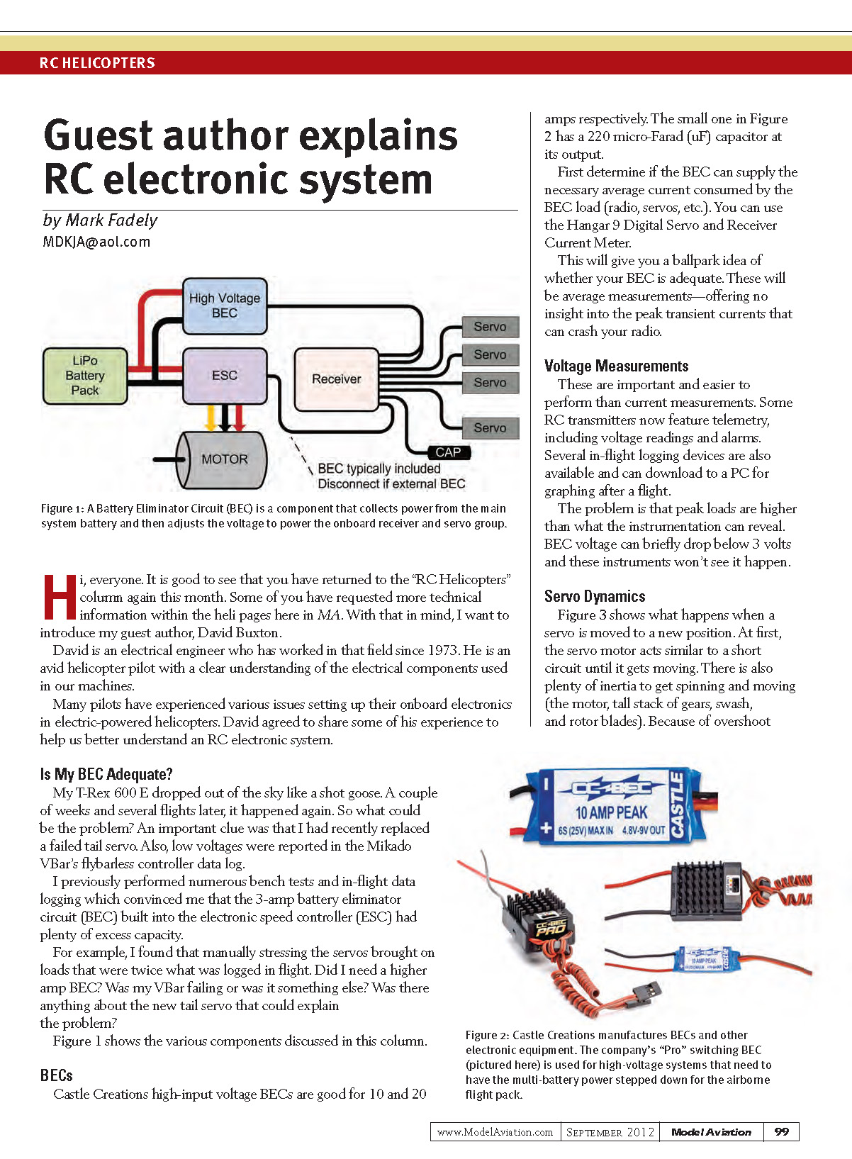
Castle Creations high-input-voltage BECs are available in 10- and 20-amp versions. The small one shown in Figure 2 has a 220 microfarad (µF) capacitor at its output.
First determine if the BEC can supply the necessary average current consumed by the BEC load (radio, servos, etc.). You can use the Hangar 9 Digital Servo and Receiver Current Meter. This will give you a ballpark idea of whether your BEC is adequate.
Note: these measurements are average values and do not reveal peak transient currents. Short voltage drops or spikes can crash your radio even when average current appears sufficient.
Voltage Measurements
Voltage measurements are important and are easier to perform than current measurements. Some RC transmitters now feature telemetry, including voltage readings and alarms. Several in-flight logging devices are also available and can download to a PC for graphing after a flight.
The problem is that peak loads are higher than what most instrumentation can reveal. BEC voltage can briefly drop below 3 volts and these instruments won’t always see it happen.
Servo Dynamics
Figure 3 shows what happens when a servo is moved to a new position. At first, the servo motor behaves similar to a short circuit until it gets moving. There is also plenty of inertia to overcome (the motor, tall stack of gears, swash, and rotor blades). Because of overshoot recovery, the servo consumes more energy coming to a stop, starting up in the other direction, and then stopping again.
These pulses of energy explain why vigorously stirring the sticks will create stronger surges of load current than manually forcing the servo arms. Start and stop currents are higher than what it takes for servos to hold position under load.
Analog Servos
The typical receiver sends its control signals to each servo one at a time. Analog servos will draw their pulse of current accordingly, one at a time. If the servos are drawing 1-amp pulses, then the peak current drawn from the BEC will be 1 amp. If the receiver is programmed for servo sync, then the associated servo currents will add together (see Figure 5).
Digital Servos
Digital servos draw pulses of current that are shorter, at a higher rate, and are not synchronized. Occasionally all four servos (three swash servos and one tail servo) will fire in unison (see Figure 4), resulting in the occasional 4-amp spike (assuming 1 amp per servo).
Caution: not all digital servos behave the same with regard to modulation (pulse width, pulse rate, and pulse amplitude). Some high-speed digital servos produce much larger start/stop transients and can draw 4-amp, 10-amp, or higher pulses.
Capacitor Analogy
Move out to the country and drill a well. To your great disappointment, it only produces two gallons per minute. Do you drill a deeper well or install a storage tank?
With a tank installed, you can quickly fill the bathtub despite the slow flow of water from the well. A larger tank will allow you to quickly fill the bathtub after watering the lawn and garden. A large capacitor for your helicopter can accomplish much the same for brief, high-current demands.
Plug-In Capacitors
The system solution for transient high-current pulses is to plug a capacitor into an unused receiver channel. Using one with a value of 4700 µF at 10 volts and an application rule of roughly 1000 µF per servo is a good starting point. Double or triple that for aggressively high-speed servos and servos used in Giant Scale aircraft. The ideal capacitor value depends on many factors specific to each setup.
For most heli pilots, a 4700 µF capacitor stands a good chance of making a 3-amp BEC safe to use. There are tests you can perform to verify the solution, just in case.
Figure references:
- Figure 1: System components overview
- Figure 2: Small Castle Creations BEC with 220 µF output capacitor
- Figure 3: Servo movement and current pulses
- Figure 4: Uncontrolled simultaneous firing of digital servos
- Figure 5: Servo sync causing additive current draw
Transcribed from original scans by AI. Minor OCR errors may remain.

