
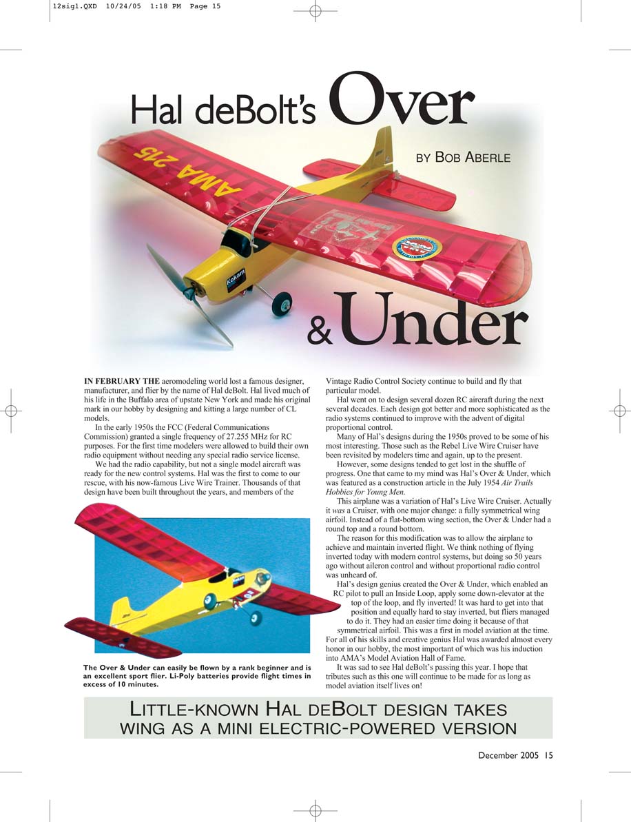
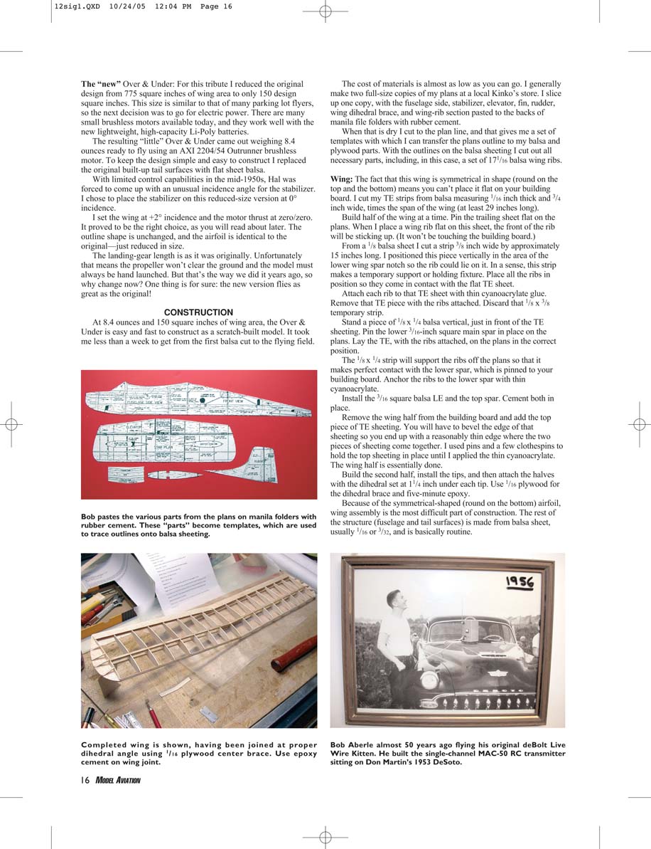
Hal deBolt’s Over & Under
BY BOB ABERLE
IN FEBRUARY THE aeromodeling world lost a famous designer, manufacturer, and flier by the name of Hal deBolt. Hal lived much of his life in the Buffalo area of upstate New York and made his original mark in our hobby by designing and kitting a large number of CL models.
In the early 1950s the FCC (Federal Communications Commission) granted a single frequency of 27.255 MHz for RC purposes. For the first time modelers were allowed to build their own radio equipment without needing any special radio service license.
We had the radio capability, but not a single model aircraft was ready for the new control systems. Hal was the first to come to our rescue, with his now-famous Live Wire Trainer. Thousands of that design have been built throughout the years, and members of the Vintage Radio Control Society continue to build and fly that particular model.
Hal went on to design several dozen RC aircraft during the next several decades. Each design got better and more sophisticated as the radio systems continued to improve with the advent of digital proportional control.
Many of Hal's designs during the 1950s proved to be some of his most interesting. Those such as the Rebel Live Wire Cruiser have been revisited by modelers time and again, up to the present.
However, some designs tended to get lost in the shuffle of progress. One that came to my mind was Hal's Over & Under, which was featured as a construction article in the July 1954 Air Trails Hobbies for Young Men.
This airplane was a variation of Hal's Live Wire Cruiser. Actually it was a Cruiser, with one major change: a fully symmetrical wing airfoil. Instead of a flat-bottom wing section, the Over & Under had a round top and a round bottom.
The reason for this modification was to allow the airplane to achieve and maintain inverted flight. We think nothing of flying inverted today with modern control systems, but doing so 50 years ago without aileron control and without proportional radio control was unheard of.
Hal's design genius created the Over & Under, which enabled an RC pilot to pull an inside loop, apply some down-elevator at the top of the loop, and fly inverted! It was hard to get into that position and equally hard to stay inverted, but fliers managed to do it. They had an easier time doing it because of the symmetrical airfoil. This was a first in model aviation at the time.
For all of his skills and creative genius Hal was awarded almost every honor in our hobby, the most important of which was his induction into AMA's Model Aviation Hall of Fame.
It was sad to see Hal deBolt's passing this year. I hope that tributes such as this one will continue to be made for as long as model aviation itself lives on!
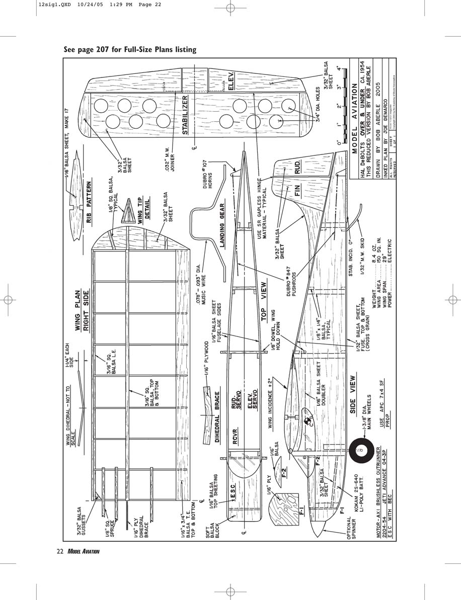
The "new" Over & Under: For this tribute I reduced the original design from 775 square inches of wing area to only 150 design square inches. This size is similar to that of many parking lot flyers, so the next decision was to go for electric power. There are many small brushless motors available today, and they work well with the new lightweight, high-capacity Li-Poly batteries.
The resulting "little" Over & Under came out weighing 8.4 ounces ready to fly using an AXI 2204/54 Outrunner brushless motor. To keep the design simple and easy to construct I replaced the original built-up tail surfaces with flat sheet balsa.
With limited control capabilities in the mid-1950s, Hal was forced to come up with an unusual incidence angle for the stabilizer. I chose to place the stabilizer on this reduced-size version at 0° incidence.
I set the wing at +2° incidence and the motor thrust at zero/zero. It proved to be the right choice, as you will read about later. The outline shape is unchanged, and the airfoil is identical to the original — just reduced in size.
The landing-gear length is as it was originally. Unfortunately that means the propeller won't clear the ground and the model must always be hand launched. But that's the way we did it years ago, so why change now? One thing is for sure: the new version flies as great as the original!
CONSTRUCTION
At 8.4 ounces and 150 square inches of wing area, the Over & Under is easy and fast to construct as a scratch-built model. It took me less than a week to get from the first balsa cut to the flying field.
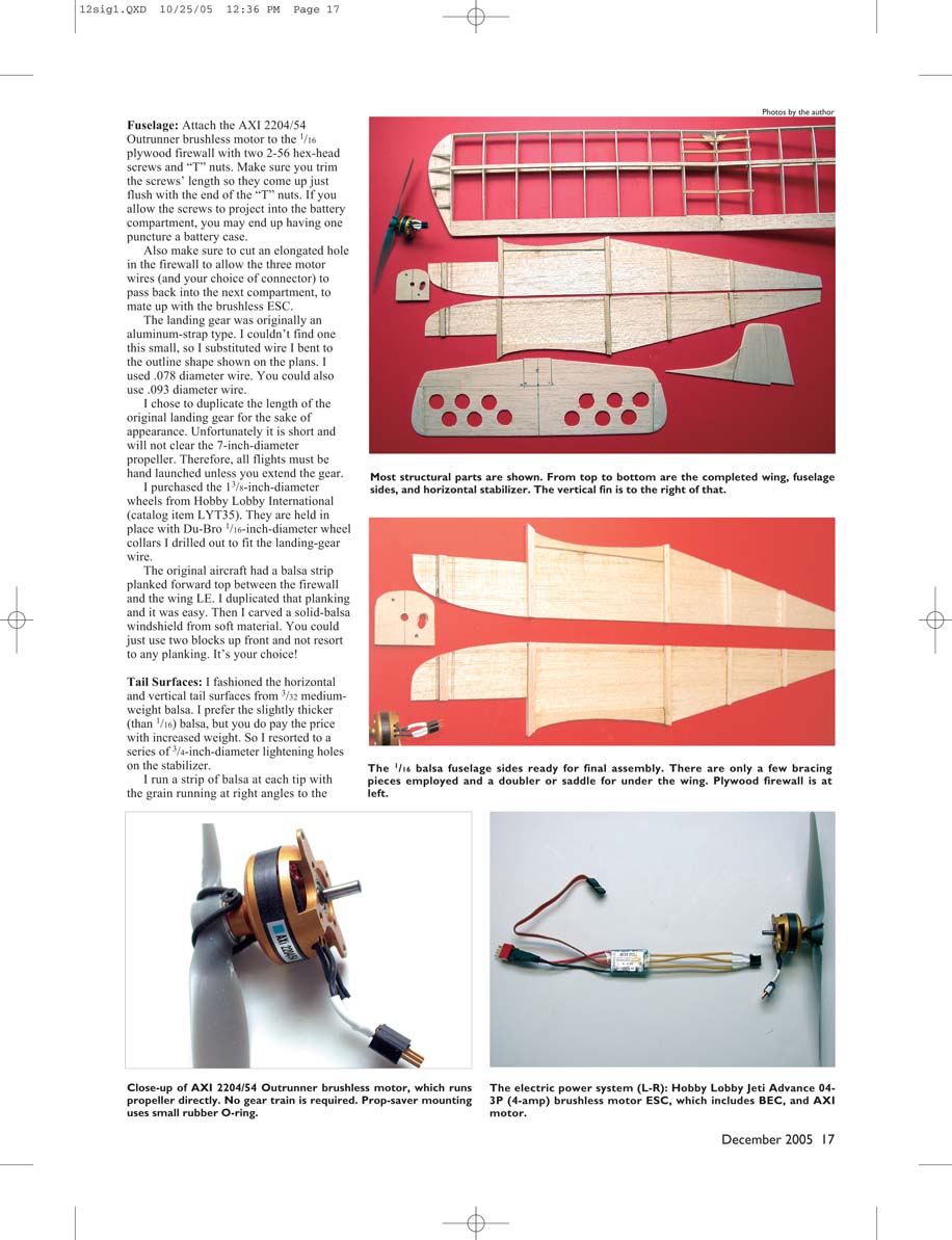
The cost of materials is almost as low as you can go. I generally make two full-size copies of my plans at a local Kinko's store. I slice up one copy, with the fuselage side, stabilizer, tailbone, fin, rudder, wing dihedral brace, and wing-rib section pasted to the backs of manila file folders with rubber cement.
When that is dry I cut to the plan line, and that gives me a set of templates with which I can transfer the plans outline to my balsa and plywood parts. With the outlines on the balsa sheeting I cut out all necessary parts, including, in this case, a set of 1/16" balsa wing ribs.
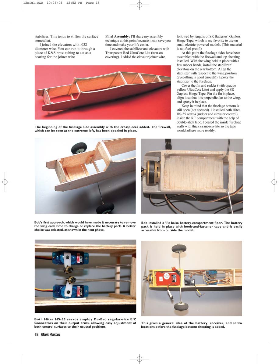
Note: The fact that this wing is symmetrical in shape (round on the top and the bottom) means you can't place it flat on your building board. I cut my TE strips from balsa measuring 1/8" thick and 3/4" wide, times the span of the wing (at least 29 inches long).
Build half of the wing at a time. Pin the trailing sheet flat on the plans. When I place a wing rib flat on this sheet, the front of the rib will be sticking up. (It won't be touching the building board.)
From a 1/8" balsa sheet I cut a strip 3/8" thick and wide by approximately 15 inches long. I positioned this piece vertically in the area of the lower wing spar notch so the rib could lie on it. In a sense, this strip acts as a temporary support or holding fixture. Place all the ribs in position so they come in contact with the flat TE sheet.
Attach each rib to that TE sheet with thin cyanoacrylate glue. Remove that TE piece with the ribs attached. Discard that 1/8" x 3/8" temporary strip.
Stand a piece of 1/8" x 1/4" balsa vertical, just in front of the TE sheeting. Pin the lower 3/16-inch square main spar in place on the plans. Lay the TE, with the ribs attached, on the plans in the correct position.
The 1/8" x 1/4" strip will support the ribs off the plans so that it makes perfect contact with the lower spar, which is pinned to your building board. Anchor the ribs to the lower spar with thin cyanoacrylate.
Install the 3/16 square balsa LE and the top spar. Cement both in place.
Remove the wing half from the building board and add the top piece of TE sheeting. You will have to bevel the edge of that sheeting so you end up with a reasonably thin edge where the two pieces of sheeting come together. I used pins and a few clothespins to hold the top sheeting in place until I applied the thin cyanoacrylate. The wing half is essentially done.
Build the second half, install the tips, and then attach the halves with the dihedral set at 1 1/4 inch under each tip. Use 1/16 plywood for the dihedral brace and five-minute epoxy.
Because of the symmetrical-shaped (round on the bottom) airfoil, wing assembly is the most difficult part of construction. The rest of the structure (fuselage and tail surfaces) is made from balsa sheet, usually 1/16 or 3/32, and is basically routine.
Fuselage
Attach the AXI 2204/54 Outrunner brushless motor to the 1/16 plywood firewall with two 2-56 hex-head screws and "T" nuts. Make sure you trim the screws' length so they come up just flush with the end of the "T" nuts. If you allow the screws to project into the battery compartment, you may end up having one puncture a battery case.
Also make sure to cut an elongated hole in the firewall to allow the three motor wires (and your choice of connector) to pass back into the next compartment, to mate up with the brushless ESC.
The landing gear was originally an aluminum-strap type. I couldn't find one this small, so I substituted wire I bent to the outline shape shown on the plans. I used .078 diameter wire. You could also use .093 diameter wire.
I chose to duplicate the length of the original landing gear for the sake of appearance. Unfortunately it is short and will not clear the 7-inch-diameter propeller. Therefore, all flights must be hand launched unless you extend the gear.
I purchased the 7/8-inch-diameter wheels from Hobby Lobby International (catalog item LYT35). They are held in place with Du-Bro 1/16-inch-diameter wheel collars I drilled out to fit the landing-gear wire.
The original aircraft had a balsa strip planked forward top between the firewall and the wing LE. I duplicated that planking and it was easy. Then I carved a solid-balsa windshield from soft material. You could just use two blocks up front and not resort to any planking. It's your choice!
Tail Surfaces
I fashioned the horizontal and vertical tail surfaces from 3/32 medium-weight balsa. I prefer the slightly thicker (than 1/16) balsa, but you do pay the price with increased weight. So I resorted to a series of 3/32-inch-diameter lightening holes on the stabilizer.
I run a strip of balsa at each tip with the grain running at right angles to the stabilizer. This tends to stiffen the surface somewhat.
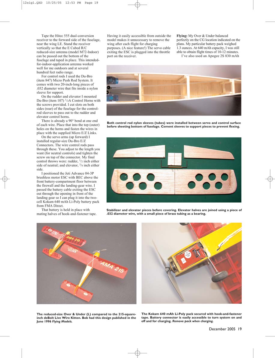
I joined the elevators with .032 diameter wire. You can run it through a piece of K&S brass tubing to act as a bearing for the joiner wire.
Final Assembly
I'll share my assembly technique at this point because it can save you time and make your life easier.
I covered the stabilizer and elevators with Transparent Red UltraCote Lite (iron-on covering). I added the elevator joiner wire, followed by lengths of SR Batteries' Gapless Hinge Tape, which is my favorite to use on small electric-powered models. (This material is not fuel-proof.)
At this point the fuselage sides have been assembled with the firewall and top sheeting installed. With the wing held in place with a few rubber bands, install the stabilizer/elevators on the rear bottom. Align the stabilizer with respect to the wing position (eyeballing is good enough!). Epoxy the stabilizer to the fuselage.
Cover the fin and rudder (with opaque yellow UltraCote Lite) and apply the SR Gapless Hinge Tape. Pin the fin in place, align it so that it is perpendicular to the wing, and epoxy it in place.
Keep in mind that the fuselage bottom is still open (not sheeted). I installed both Hitec HS-55 servos (rudder and elevator control) inside the RC compartment with the help of double-stick tape. I coated the inside fuselage walls with thick cyanoacrylate so the tape would adhere more readily.
Tape the Hitec 555 dual-conversion receiver to the forward side of the fuselage, near the wing LE. Stand the receiver vertically so that the E Cubed R/C reduced-size antenna (model M72-Indoor) can be passed out the bottom of the fuselage and taped in place. This intended-for-indoor-application antenna worked well for me outdoors and at several hundred feet radio range.
For control rods I used the Du-Bro (item 847) Micro Push Rod System. It comes with two 20-inch-long pieces of .032 diameter wire that fits inside a nylon sleeve for support.
On the rudder and elevator I mounted Du-Bro (item 107) 1/2A Control Horns with the screws provided. I cut slots on both sides (rear) of the fuselage for the control-rod sleeves to pass out to the rudder and elevator control horns.
There is already a 90° bend at one end of each wire. Place that into the top (outer) holes on the horns and fasten the wires in place with the supplied Micro E/Z Links.
On the servo arms (up forward) I installed regular-size Du-Bro E/Z Connectors. The wire control rods pass through these. You adjust to the length you want (for neutral controls) and tighten the screw on top of the connector. My final control throws were: rudder, 1/2 inch each side of neutral; and elevator, 3/8 inch either side.
I positioned the Jeti Advance 04-3P brushless motor ESC with BEC above the front battery-compartment floor between the firewall and the landing-gear wire. I passed the battery cable exiting the ESC out through the opening in front of the landing gear so I can plug it into the two-cell Kokam 640 mAh Li-Poly battery pack from FMA Direct.
That battery is held in place with mating halves of hook-and-fastener tape.
Having it easily accessible from outside the model makes it unnecessary to remove the wing after each flight for charging purposes. (A nice feature!) The servo cable exiting the ESC is plugged into the throttle port on the receiver.
Flying
My Over & Under balanced perfectly on the CG location indicated on the plans. My particular battery pack weighed 1.3 ounces. At 640 mAh capacity, I was still able to obtain flight times of 10-12 minutes.
I've also used an Apogee 2S 830 mAh Li-Poly pack, which weighs 1.5 ounces and provides flight times of 13-15 minutes. It fits into the same-size battery compartment.
As I pointed out, the Over & Under must be hand launched with the landing-gear length shown on the plans. The first flight was perfect, requiring no trim. It just flew out of Tom Hunt's hand as if it had done that for a long time.
The Over & Under is extremely smooth in flight and simple to fly. It has enough power that an easily throttle back to roughly half and still stay comfortably in flight. Going to full power, you can loop it from level flight. We even tried a few crazy maneuvers such as snap barrel rolls (I guess that's the best description). Tailspins from high altitude are fun to watch.
Oddly enough, the only thing this model didn't do well was fly inverted. Without ailerons, the best way to get it inverted is to pull half an inside loop and apply down-elevator just at the top. Then the trick is to hold in just enough down to keep the nose up. Remember that with rudder and no aileron control, your left is right and your right is left when inverted.
Probably owing to a bit too much dihedral, my Over & Under tends to fall out of inverted flight quickly. At times the recovery is a little unnerving. If you try inverted flying, do it at a higher altitude in case you get into trouble.
I wasn't disappointed by this one partial failure because I still have an excellent, small, electric-powered sport flier. Bring this airplane to a Vintage Radio Control Society fly-in, and you will surely draw a lot of attention.
You did good, Hal! MA Bob Aberle [email protected]
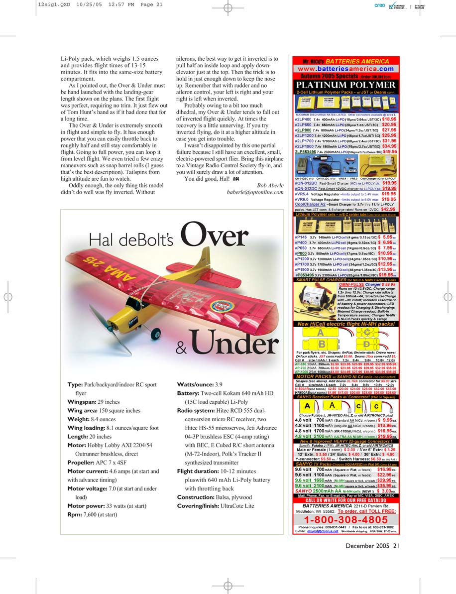
Hal deBolt's Over & Under
- Type: Park/backyard/indoor RC sport flyer
- Wingspan: 29 inches
- Wing area: 150 square inches
- Weight: 8.4 ounces
- Wing loading: 8.1 ounces/square foot
- Length: 20 inches
- Motor: Hobby Lobby AXI 2204/54 Outrunner brushless, direct
- Propeller: APC 7 x 4SF
- Motor current: 4.6 amps (at start and with advance timing)
- Motor voltage: 7.0 (at start and under load)
- Motor power: 33 watts (at start)
- Rpm: 7,600 (at start)
- Watts/ounce: 3.9
- Battery: Two-cell Kokam 640 mAh HD (15C load capable) Li-Poly
- Radio system: Hitec RCD 555 dual-conversion micro RC receiver, two Hitec HS-55 microservos, Jeti Advance 04-3P brushless ESC (4-amp rating) with BEC, E Cubed R/C short antenna (M-72-Indoor), Polk's Tracker II synthesized transmitter
- Flight duration: 10-12 minutes plus with 640 mAh Li-Poly battery with throttling back
- Construction: Balsa, plywood
- Covering/finish: UltraCote Lite
Transcribed from original scans by AI. Minor OCR errors may remain.

