
HANSA-BRANDENBURG W.29 ARF
FLY A UNIQUE WORLD WAR I FLOATPLANE
by Greg Gimlick
Wow! That was my first impression when I opened the box and worked my way through all of the protective wrap and tape. The model arrived double boxed and well prepared for its trek across the country.
The covering was well done with no wrinkles and the airplane’s design was enough to get me excited about starting the build. I’ll confess to temporarily slapping the wings and tail on so I could admire it and make airplane noises. My wife is used to this by now.
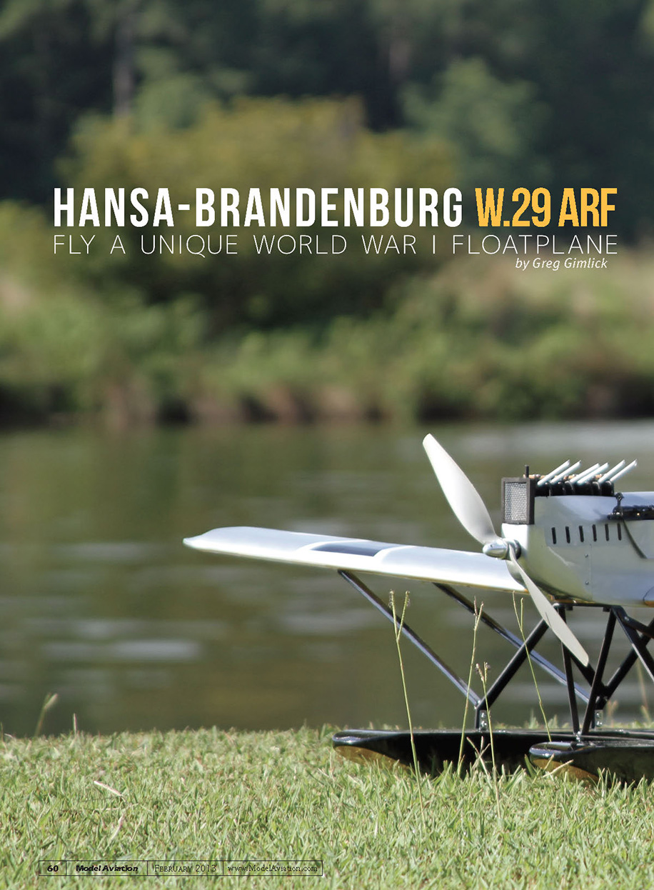
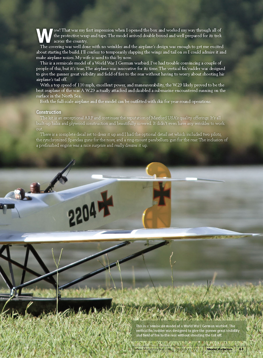
This is a semiscale model of a World War I German warbird. I’ve had trouble convincing a couple of people of this, but it’s true. The airplane was innovative for its time. The vertical fin/rudder was designed to give the gunner great visibility and field of fire to the rear without having to worry about shooting his airplane’s tail off.
With a top speed of 110 mph, excellent power, and maneuverability, the W.29 likely proved to be the best seaplane of the war. A W.29 actually attacked and disabled a submarine encountered running on the surface in the North Sea.
Both the full-scale airplane and the model can be outfitted with skis for year-round operations.
Construction
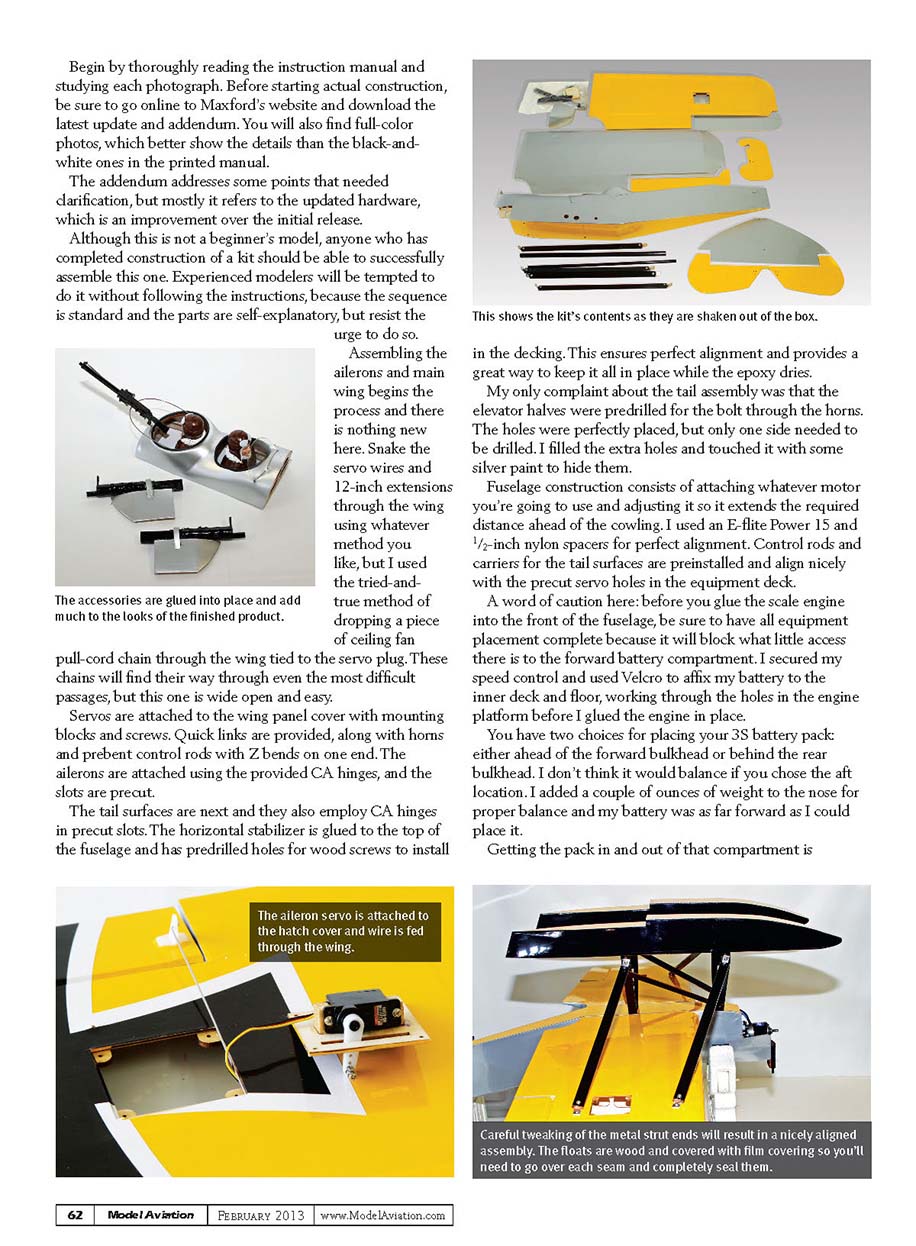
The kit is an exceptional ARF and continues the reputation of Maxford USA’s quality offerings. It’s all built-up balsa and plywood construction and beautifully covered. It didn’t even have any wrinkles to work out.
There is a complete decal set to dress it up and I had the optional detail set which included two pilots, the synchronized Spandau guns for the nose, and a ring-mount parabellum gun for the rear. The inclusion of a prefinished engine was a nice surprise and really dresses it up.
My only complaint about the tail assembly was that the elevator halves were predrilled for the bolt through the horns. The holes were perfectly placed, but only one side needed to be drilled. I filled the extra holes and touched them with some silver paint to hide them.
Fuselage construction consists of attaching whatever motor you're going to use and adjusting it so it extends the required distance ahead of the cowling. I used an E-flite Power 15 and 1/2-inch nylon spacers for perfect alignment. Control rods and carriers for the tail surfaces are preinstalled and align nicely with the precut servo holes in the equipment deck.
A word of caution here: before you glue the scale engine into the front of the fuselage, be sure to have all equipment placement complete because it will block what little access there is to the forward battery compartment. I secured my speed control and used Velcro to affix my battery to the inner deck and floor, working through the holes in the engine platform before I glued the engine in place.
You have two choices for placing your 3S battery pack: either ahead of the forward bulkhead or behind the rear bulkhead. I don't think it would balance if you chose the aft location. I added a couple of ounces of weight to the nose for proper balance and my battery was as far forward as I could place it.
Getting the pack in and out of that compartment is challenging and I have to trust the Velcro, because there is no way to reach in and secure it with a wraparound strap. So far, that has not been an issue.
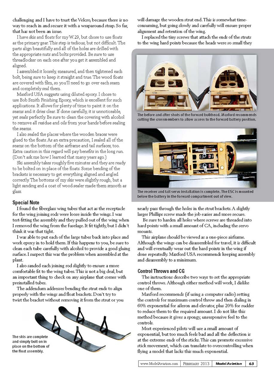
I have skis and floats for my W.29, but chose to use floats as the primary gear. This step is tedious, but not difficult. The parts align beautifully and all of the holes are drilled with the appropriate nuts and bolts provided. Be sure to use threadlocker on each one after you get it assembled and aligned.
I assembled the floats loosely, measured, and then tightened each bolt, being sure to keep everything straight and true. The wood floats are covered with film, so you'll need to go over each seam and completely seal them.
Maxford USA suggests using diluted epoxy. I chose to use Bob Smith Finishing Epoxy, which is excellent for such applications. It allows for plenty of time to paint it on the seams and it dries clear. If done carefully, it is unnoticeable, yet seals perfectly. Be sure to clean the covering with alcohol to remove all residue and oils from your hands before sealing the seams.
I also sealed the places where the wooden braces were glued to the floats. As an extra precaution, I sealed all of the seams on the bottom of the airframe and tail surfaces, too. Extra caution in this regard will pay benefits in the long run. (Don't ask me how I learned that many years ago.)
Ski assembly takes roughly five minutes and they are ready to be bolted on in place of the floats. Some bending of the brackets is necessary to get everything aligned and angled correctly. The bottoms of my skis were slightly rough, but a light sanding and a coat of wood sealer made them smooth as glass.
Special Note
I found the fiberglass wing tubes that act as the receptacle for the wing joining rods were loose inside the wings. I was test-fitting the assembly and they pulled out of the wing when I removed the wing from the fuselage. It fit tightly, but I didn't think it was that tight.
I was able to put each of the large tubes back into place and work epoxy in to hold them. If this happens to you, be sure to clean each tube carefully with alcohol to provide a good gluing surface. I suspect this was the problem when assembled at the plant.
I also sanded each joining rod slightly to ensure a more comfortable fit to the wing tubes. This is not a big deal, but an important thing to check on any airplane that comes with preinstalled tubes.
The addendum addresses bending the strut ends to align properly with the wings and float brackets. Don't try to twist the bracket without removing it from the strut or you will damage the wooden strut end. This is somewhat time-consuming, but going slowly and carefully will ensure proper alignment and retention of the wing.
I replaced the tiny screws that attach the ends of the struts to the wing hard points because the heads were so small they nearly pass through the holes in the strut brackets. A slightly larger Phillips screw made the job easier and more secure.
Be sure to harden all holes where screws are threaded into hard points with a small amount of CA, including the servo mounts.
This airplane should be viewed as a one-piece airframe. Although the wings can be disassembled for travel, it is difficult and will eventually wear out the hard points in the wing if done repeatedly. Maxford USA recommends keeping assembly and disassembly to a minimum.
Control Throws and CG
The instructions describe two ways to set the appropriate control throws. Although either method will work, I dislike one of them.
Maxford recommends (if using a computer radio) setting the controls for maximum control throw and then dialing in 60% exponential for aileron and elevator, plus 20% for rudder to reduce them to the required amount. I do not like this method because it gives a spongy, unresponsive feel to the controls.
Most experienced pilots will use a small amount of exponential, but too much feels bad and all the deflection is at the extreme ends of the sticks. This can promote excessive stick movement, which can translate to overcontrolling when flying a model that lacks this much exponential.
I prefer the second method recommended (for non-computer radios). This uses mechanical adjustments with the servo wheels and control horns to achieve the proper throws. This method has been taught for years. It gives the perfect throws without resorting to electronic means. When things are set up in this manner, you can trim as necessary with your preferred exponential amounts. The suggested control throws and CG location worked nicely.
The CG, as it sets in the water, is nearly perfect, although the airplane sets slightly tail low. It levels out as soon as you apply some throttle. Because there is no water rudder, you will find yourself using a lot of rudder to keep it taxiing straight on the water if you’re too aggressive on the throttle.
Flying
This is why I bought it in the first place, isn’t it? Doing a test flight off of water is always a nervous moment for me, but this one didn’t show me any new tricks to scare me. The takeoff run was almost nonexistent on the first flight.
The motor has a lot of torque and I powered it up faster than I should have, so it needed some immediate rudder input to counteract the torque. As it broke the surface I was afraid that it would veer off because of the amount of rudder I had in, but it was easily controllable and the airplane climbed gracefully.
After a couple of circuits and the addition of a click or two of trim, the airplane felt like a big trainer. Controls were adequate on low rates and comfortable on high. I used my standard 20% exponential and that worked for me. Stalls were uneventful and the nose dropped off gently, but it tends to drop a wing.
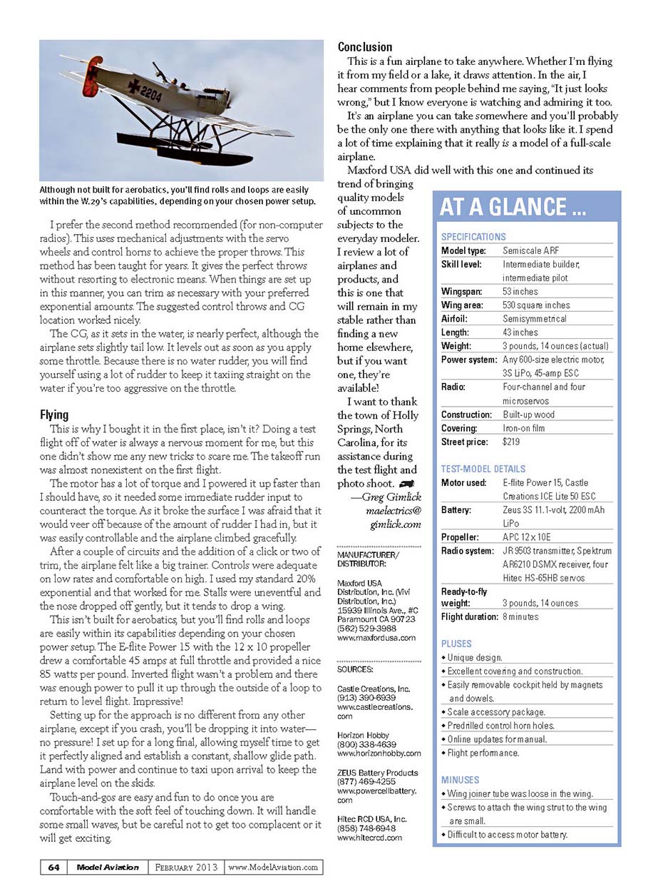
This isn’t built for aerobatics, but you’ll find rolls and loops are easily within its capabilities depending on your chosen power setup. The E-flite Power 15 with the 12 x 10 propeller drew a comfortable 45 amps at full throttle and provided a nice 85 watts per pound. Inverted flight wasn’t a problem and there was enough power to pull it up through the outside of a loop to return to level flight. Impressive!
Setting up for the approach is no different from any other airplane, except if you crash, you’ll be dropping it into water—no pressure! I set up for a long final, allowing myself time to get it perfectly aligned and establish a constant, shallow glide path. Land with power and continue to taxi upon arrival to keep the airplane level on the skids.
Touch-and-goes are easy and fun to do once you are comfortable with the soft feel to the touchdown. It will handle some small waves, but be careful not to get too complacent or it will get exciting.
Conclusion
This is a fun airplane to take anywhere. Whether I’m flying it from my field or a lake, it draws attention. In the air, I hear comments from people behind me saying, “It just looks wrong,” but I know everyone is watching and admiring it too.
It’s an airplane you can take somewhere and you’ll probably be the only one there with anything that looks like it. I spend a lot of time explaining that it really is a model of a full-scale airplane.
Maxford USA did well with this one and continued its trend of bringing quality models of uncommon subjects to the everyday modeler. I review a lot of airplanes and products, and this is one that will remain in my stable rather than finding a new home elsewhere, but if you want one, they’re available!
I want to thank the town of Holly Springs, North Carolina, for its assistance during the test flight and photo shoot.
— Greg Gimlick
AT A GLANCE ...
SPECIFICATIONS
- Model type: Semiscale ARF
- Skill level: Intermediate builder, intermediate pilot
- Wingspan: 53 inches
- Wing area: 530 square inches
- Airfoil: Semisymmetrical
- Length: 43 inches
- Weight: 3 pounds, 14 ounces (actual)
- Power system: Any 600-size electric motor, 3S LiPo, 45-amp ESC
- Radio: Four-channel and four micro servos
- Construction: Built-up wood
- Covering: Iron-on film
- Street price: $219
TEST-MODEL DETAILS
- Motor used: E-flite Power 15, Castle Creations ICE Lite 50 ESC
- Battery: Zeus 3S 11.1-volt, 2200 mAh LiPo
- Propeller: APC 12 x 10E
- Radio system: JR 9503 transmitter, Spektrum AR6210 DSMX receiver, four Hitec HS-65HB servos
- Ready-to-fly weight: 3 pounds, 14 ounces
- Flight duration: 8 minutes
PLUSES
- Unique design
- Excellent covering and construction
- Easily removable cockpit held by magnets and dowels
- Scale accessory package
- Predrilled control horn holes
- Online updates for manual
- Flight performance
MINUSES
- Wing joiner tube was loose in the wing
- Screws to attach the wing strut to the wing are small
- Difficult to access motor battery
Transcribed from original scans by AI. Minor OCR errors may remain.

