
Heinkel 100D Stunt - 2009/01
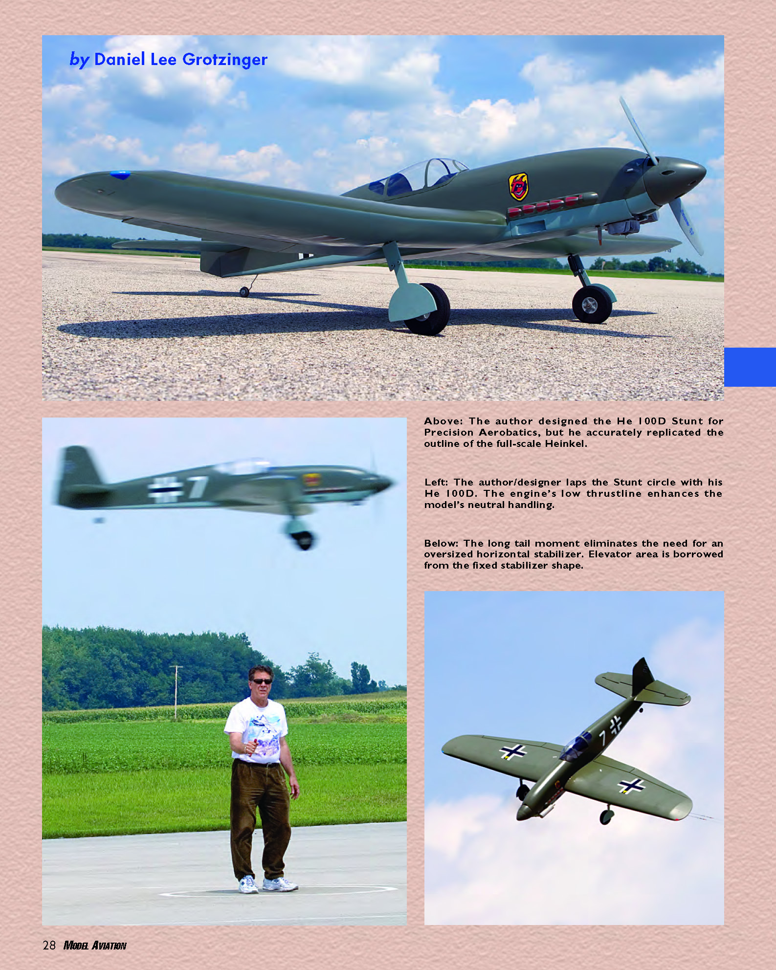
by Daniel Lee Grotzinger
THE HEINKEL He 100D is a little-known, seldom-modeled aircraft that could have become the mainstay of the Luftwaffe during World War II. It was built as a follow-up to the He 112; Heinkel’s original design entry when the Reich Air Ministry issued specifications for a new fighter in 1935.
The He 100, sometimes designated “He 113,” was in many ways superior to the Messerschmitt Me 109, which had initially won the Reich Air Ministry’s competition over the He 112. But Heinkel was not awarded a production contract, mostly because of politics. As with the Bell P-39, there was little margin for weight-increasing modifications.
For a short time, clipped-wing preproduction model He 100 V8 held an absolute world speed record at 463.92 mph. For more information see Schiffer Military History volume 52 and Aero Publishers number 12.
You never forget your first love; that is certainly true of my experience in model aviation. I was an avid control-line (CL) Precision Aerobatics (Stunt) builder and flier from 1960 until 1966. During those formative years I devoured every article I could find about aerodynamics, especially pertaining to Stunt application.
During the next 30 years I alternated between activity and inactivity in CL and RC because of military service, college, raising a family, and work. However, I followed the design articles—especially those by Al Rabe—and I agreed with the direction he was taking Stunt design.
I learned about the He 100 while researching for an RC scale Focke-Wulf Fw 190D. Later I acquired a 1/5-scale He 100D from Dennis Wann in Bryan, Ohio. I loved it and kept thinking that it deserved to be made into a close-to-scale Stunter, although that would be a challenge. I got fired up and started drawing after the 2002 Nats. Then the balsa chips started flying.
Large models fly better because of a somewhat more favorable Reynolds number. My bad shoulder did not want the pull of a .60 engine, so I compromised on a .51 (which I already had). Rather than force a scale appearance on a set of Stunt design numbers, I worked backward and altered the scale three-views as little as possible to arrive at what my instincts told me would work.
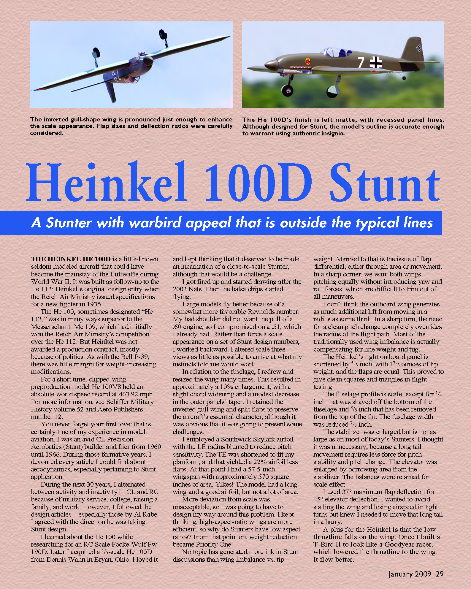
In relation to the fuselage I redrew and resized the wing many times. This resulted in approximately a 10% enlargement, with a slight chord widening and a modest decrease in the outer panels’ taper. I retained the inverted gull wing and split flaps to preserve the aircraft’s essential character, although it was obvious that it was going to present some challenges.
I employed a Southwick Skylark airfoil with the leading-edge radius blunted to reduce pitch sensitivity. The trailing edge was shortened to fit my planform, yielding a 22% airfoil (less flaps). At that point I had a 57.5-inch wingspan with approximately 570 square inches of area. The model had a long wing and a good airfoil, but not a lot of area.
More deviation from scale was unacceptable, so I was going to have to design my way around this problem. I kept thinking: high-aspect-ratio wings are more efficient, so why do Stunters have low aspect ratios? From that point on, weight reduction became Priority One.
No topic has generated more ink in Stunt discussions than wing imbalance vs. tip weight. Married to that is the issue of flap differential, either through area or movement. In a sharp corner we want both wings pitching equally without introducing yaw and roll forces, which are difficult to trim out of all maneuvers. I don’t think the outboard wing generates as much additional lift from moving in a radius as some think. In a sharp turn, the need for a clean pitch change completely overrides the radius of the flight path. Most of the traditionally used wing imbalance is actually compensating for line weight and tug.
For the Heinkel:
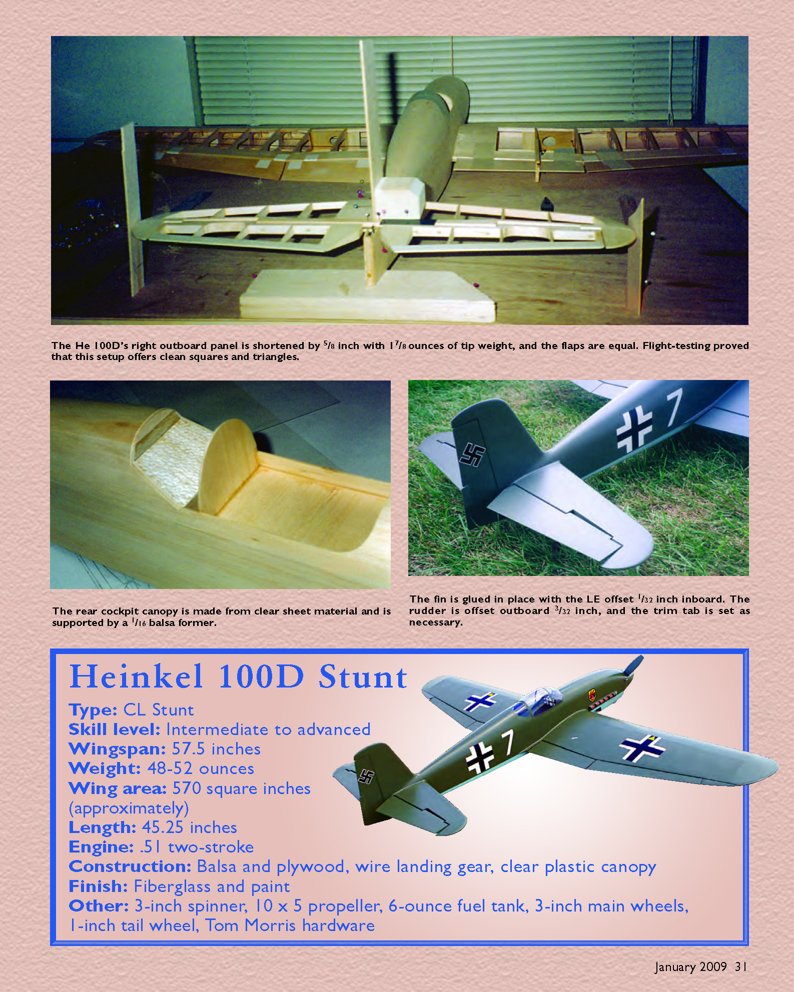
- The right outboard panel is shortened by 5/8".
- Tip weight is 1 7/8 oz on the right outboard panel.
- The flaps are equal (no flap-area differential).
This proved to give clean squares and triangles in flight-testing.
The fuselage profile is scale except for minor reductions: 1/4" shaved off the bottom of the fuselage, 3/8" removed from the top of the fin, and fuselage width reduced by 7/8". The stabilizer was enlarged but is not as large as on many modern Stunters; I thought a long tail movement requires less force for pitch stability and pitch change, so excessive stabilizer wasn't necessary. The elevator was enlarged by borrowing area from the stabilizer; the balances were retained for scale effect.
I used 37° maximum flap deflection with 45° elevator deflection. I wanted to avoid stalling the wing and losing airspeed in tight turns but knew I needed to move that long tail quickly.
A plus for the Heinkel is that the low thrustline falls on the wing. I once built a T-Bird II to look like a Goodyear racer, which lowered the thrustline to the wing; it flew better. The engine, tank, and spinner fall near the wing, giving a favorable vertical CG despite the tall fuselage profile.
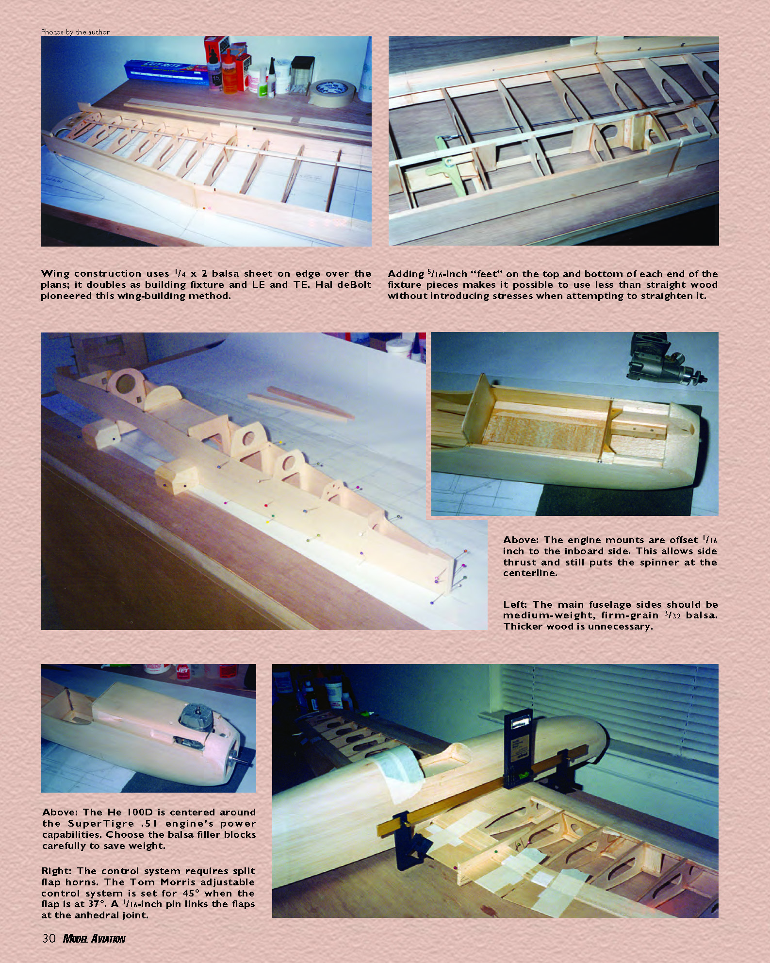
The He 100D is centered around the SuperTigre .51 engine's power capabilities. Choose the balsa filler blocks carefully to save weight. The He 100D employs a wide-blade, large-diameter, low-pitch propeller (Graupner 12 x 5). This allows the airplane to fly at a modest speed, but the wide center-section of the wing and tail gets a large volume of faster airflow and helps compensate for a small wing and long tail.
I used slightly more than 1° of engine side thrust to hold the Heinkel on the lines at a lower speed in overhead maneuvers. Very little rudder offset is used. I let the engine do the work for me; I don’t consider side thrust a loss of efficiency—it doesn’t create the problems that flap differential and rudder offset do.
Please realize that any airplane is an aerodynamic package. Making any one change on an existing design may or may not improve it. Together the changes I describe have worked well for the Heinkel He 100D Stunt.
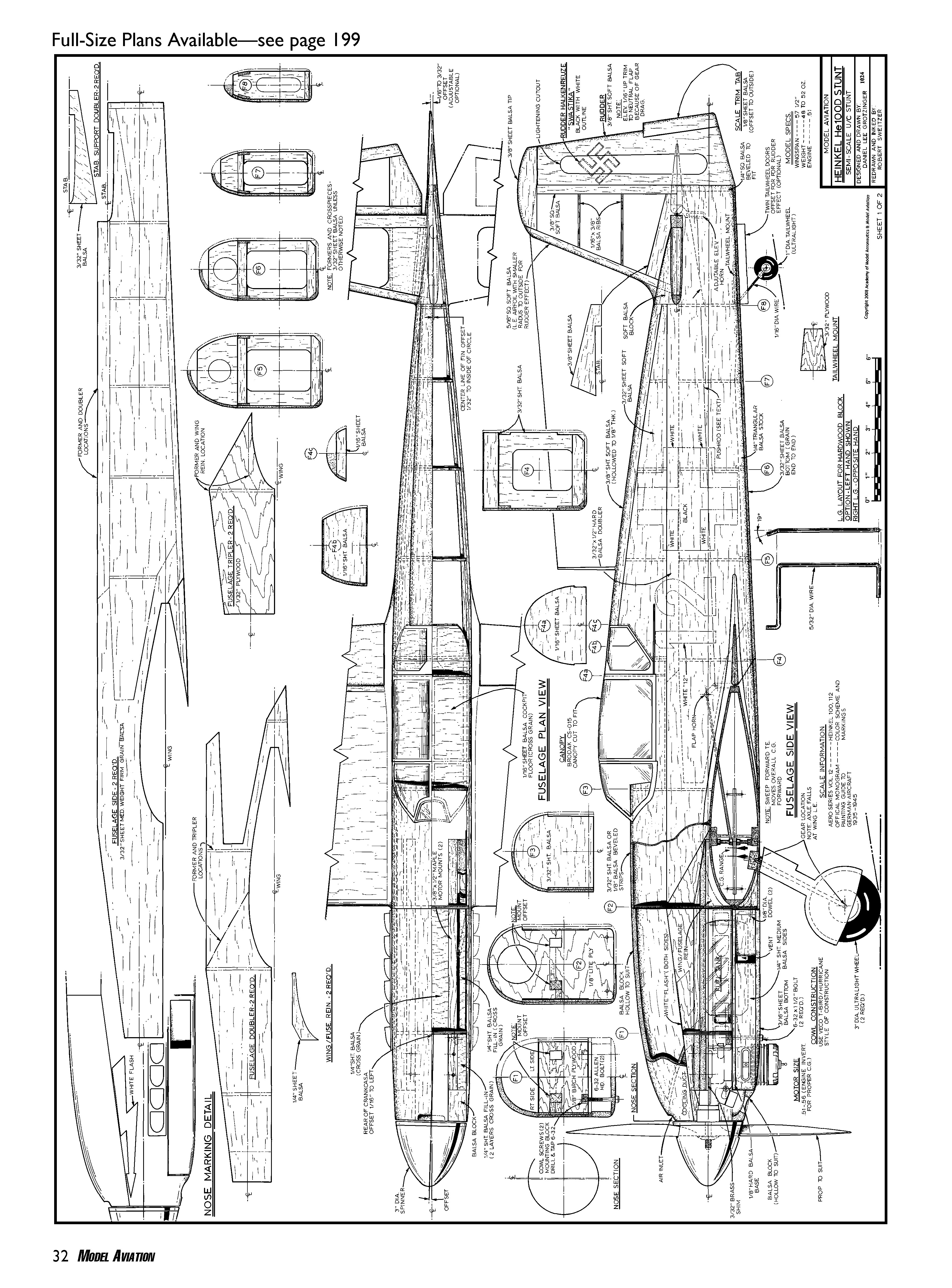
CONSTRUCTION
This section focuses on important points that differ from the usual. Because of closer adherence to scale dimensions, weight and alignment become especially important.
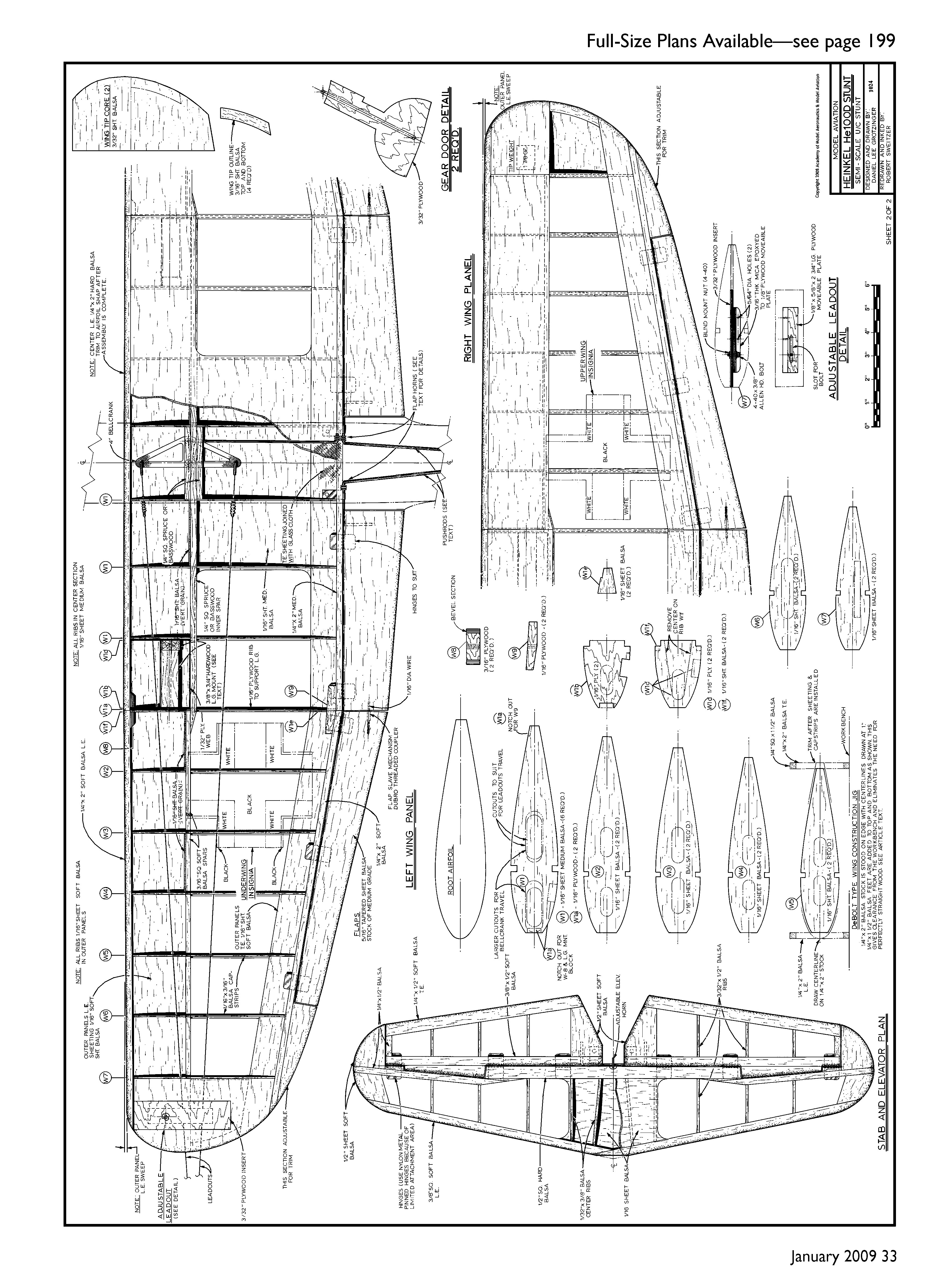
Wing
- Construction uses 1/4" x 2" balsa sheet on edge over the plans; this doubles as the building fixture and as the leading- and trailing-edge. Hal deBolt pioneered this wing-building method; I refined it by adding 5/16" "feet" on the top and bottom of each end of the fixture pieces. That allows use of less-than-straight wood without introducing stresses while straightening it.
- Draw lines on the center of the fixture width end-to-end for rib placement. Set a small adjustable square to 2 5/8" and sand all fixture ends to the same height.
- For a flat typical Stunt wing those center lines would be 1 5/16" from the top/bottom edges. To accommodate the Heinkel’s anhedral and dihedral:
- Mark the anhedral break (top-view aircraft centerline) 1/8" above the true fixture centerline (1 7/16" above the plans surface). The center section has no sweep or taper, so no joint is needed in the fixture at the anhedral break.
- Marks at each dihedral break are 5/16" lower than the anhedral mark (1 1/8" above the plans surface).
- Tip marks are 3/8" higher than the dihedral joint marks (1 1/2" above the plans surface).
- Connect these marks to create the centerline for rib placement with anhedral and dihedral built in.
- Place centerlines on each rib and glue ribs to the LE and TE by matching lines. Extend a line up from the plans onto the LE and TE with a square to position ribs accurately.
- Build the wing in one piece so you can remove it from the building surface for control installation, etc. When gluing all sheeting and cap strips, pin it flat. The wing should lay flat up or down with all feet touching the work surface; if not, check the work surface or fixture ends for accuracy.
- After sheeting and capping, remove excess fixture material and shape the LE and TE. Read the wing construction section several times while referring to the plans and photos to fully understand it.
Control System
- The control system requires split flap horns.
- Use a Tom Morris flap horn for the right flap with the left side cut off. Only this horn is connected to the bellcrank. It is also connected through the 1" hole to the elevator horn, which is a Morris adjustable set for 45° elevator when the flap is at 37°.
- Use a Tom Morris 1" elevator horn for the left flap with the right side cut off. A pushrod connects it as a soldered Y joint to the elevator pushrod roughly 10" back. This setup eliminates play, rotational inaccuracy, and differential.
- Outer flaps are slaved by a 1/16" diameter music-wire pin that enters a female receptacle (Du-Bro threaded brass connector). Install the female end first, approximately two-thirds of the way back from the hinge line.
- Carefully start a pilot hole with a straight pin, then use progressively larger drill bits turned with your fingertips for precise adjustments.
- The connector requires a stepped hole to fit properly and tight. Before pressing it in place, make pinholes in the flap surface to wick in cyanoacrylate (CA) glue and adhere the connector after it is seated.
- Temporarily mount the flaps with strong-tack masking tape to simulate cloth hinges. Mark the male pin’s position and inset it similarly (do not glue yet).
- The gap between the flaps should be a strong 1/16", beveling to approximately 5/32" at the rear to accommodate up movement. In neutral the pin should enter the brass receptacle by roughly 5/32"; neutral fit must be perfect.
- Test up and down with tape hinges tightly in place (they will bind initially because of geometry). Use a drill bit to slightly oval the mouth of the brass coupler front-to-rear. Remove the male pin, bevel and round the bottom and rear of its end, reinstall, and test again. Make small changes patiently until it is right; if needed, make a new pin.
- When satisfied, glue the flap in with CA. As a precaution, dig a trench in the bottom of the flap to expose part of the pin and fill the trench with epoxy flush to the surface to prevent loosening over time.
- Permanently mount the flaps with Tom Morris Dacron hinges, which allow freedom of movement and some tolerance for slight inaccuracy in the male/female parts.
Fuselage
- Main fuselage sides should be medium-weight, firm-grain 3/32" balsa. Thicker wood is unnecessary. Think in terms of trusses and T-beams: lots of wood is fine as long as it is kept rigid.
- Engine mounts are offset 1/16" to the inboard side; this allows side thrust while keeping the spinner on the centerline.
- The 1/2" square stabilizer center trailing-edge is hard balsa; all other tail structure is light contest balsa.
- The fin leading-edge radius is offset slightly to direct more air on the inboard side; glue the fin with the LE offset 1/32" inboard. The rudder is offset 3/32" outboard and the scale trim tab is significantly offset.
- Landing-gear legs and their composite trunnion mount (taken from a set of B & D retracts) are inset into a plywood pocket mounted in the wing. A piece of 1/16" plywood angled from the back of the top spar to the front of the bottom spar forms the back wall of this pocket and doubles as shear webbing for the wing.
- Wing center spars should be spruce or bass. The axles fall just below the LE, and the gear extends 4 1/4" from wing to axle. A traditional torsion gear and block may be used, but I prefer the inset trunnion mount method.
Finish
- Keep it light. The entire bare Heinkel was painted with one coat of AeroGloss clear.
- I applied 1/2-oz glass cloth on the fuselage with finishing resin thinned 50% with denatured alcohol. When cured, I applied a second coat to fill the pores and then sanded until the cloth surface was cut.
- Cover all open surfaces with Polyspan filled with three coats of AeroGloss clear. Use chart tape to simulate scale panel lines. Apply one generous coat of Perfect Primer and then remove the chart tape to give the panel lines depth. Then apply two coats of scale-accurate Perfect military flat. Except for markings, that’s it. The He 100D is extremely light and scale.
- Note on judging: The rule book stipulates that the airplane be judged for perfection of appearance; nowhere does it mention a high-gloss mirror finish. An accurate military finish should score as well as a nonrealistic high gloss. In this case, weight and scale appearance enter the equation.
Acknowledgments
I thank the following:
- John Florio (deceased), for being my mentor in the early years.
- Dave Gatewood (deceased), for getting me back into Stunt and his support during this project's design and building phases.
- Jack Sheeks, for his support in test-flying and encouragement to publish the design.
- Bob Hunt, for being open-minded and enthusiastic after test-flying the prototype.
Good luck with your Heinkel. Please call or write if you have questions or comments; I don’t have a computer, so I rarely check e-mail.
Daniel L. Grotzinger 6710 Greenshire Dr. Indianapolis, IN 46220 (317) 585-4808 [email protected]
Sources
- Tom Morris Accessories: J & J Hobbies—Control Line Central, (505) 332-8007, www.clcentral.com
- B&D Enterprises, (304) 753-4636, http://bdretracts.com
Transcribed from original scans by AI. Minor OCR errors may remain.

