
HET Super Sniper XL
Greg Moore [email protected]
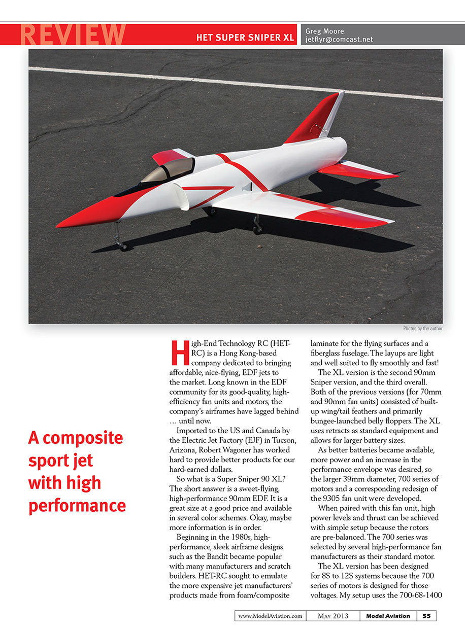
High-End Technology RC (HET-RC) is a Hong Kong-based company dedicated to bringing affordable, nice-flying, EDF jets to the market. Long known in the EDF community for its good-quality, high-efficiency fan units and motors, the company's airframes have lagged behind ... until now.
Imported to the US and Canada by the Electric Jet Factory (EJF) in Tucson, Arizona, Robert Wagoner has worked hard to provide better products for our hard-earned dollars.
So what is a Super Sniper 90 XL? The short answer is a sweet-flying, high-performance 90mm EDF. It is a great size at a good price and available in several color schemes. Okay, maybe more information is in order.
Beginning in the 1980s, high-performance, sleek airframe designs such as the Bandit became popular with many manufacturers and scratch builders. HET-RC sought to emulate the more expensive jet manufacturers' products made from foam/composite laminate for the flying surfaces and a fiberglass fuselage. The layups are light and well suited to fly smoothly and fast!
The XL version is the second 90mm Sniper version, and the third overall. Both of the previous versions (for 70mm and 90mm fan units) consisted of built-up wing/tail feathers and primarily bungee-launched belly floppers. The XL uses retracts as standard equipment and allows for larger battery sizes.
As better batteries became available, more power and an increase in the performance envelope was desired, so the larger 39mm diameter, 700 series of motors and a corresponding redesign of the 9305 fan unit were developed.
When paired with this fan unit, high power levels and thrust can be achieved with simple setup because the rotors are pre-balanced. The 700 series was selected by several high-performance fan manufacturers as their standard motor.
The XL version has been designed for 8S to 12S systems because the 700 series of motors is designed for those voltages. My setup uses the 700-68-1400 motor.
The hinges were fitted next. I used large Du-Bro pinned hinges for the ailerons because they are essentially top hinged, and Robart hinge points for the flaps. I secured my hinges with Hysol, and used a drop of melted Vaseline on the pins.
The wing is supported with a carbon-fiber tube/spar, and the roots are epoxied together. Because the roots are painted, a good sanding with 40- to 80-grit sandpaper is needed to expose the bare fiberglass and create a solid bond. I like to create small dimples with a burr to make locks and create additional strength.
I also opened the small hole to fish the thread through for the servo wires. This allows a 3/8-inch dowel to fit snugly as an antirotation feature. Open the servo wire access holes in the top of the wing, secure the pull twine, run the retract airlines, and tape them to the surface.
Next, line the wing saddle with wax paper and epoxy the wings (with the spar/tube and dowel covered with epoxy in place) and bolt the wing to the fuselage, ensuring that everything aligns. Secure it with masking tape and let it thoroughly dry.
The steering arm is too wide for its opening, so I trimmed it and drilled new holes. I chose to mount the Hitec HS-85 servo at an angle toward the steering arm, which provided a short and precise link with minimal chance of fouling the lines when the gear retracts.
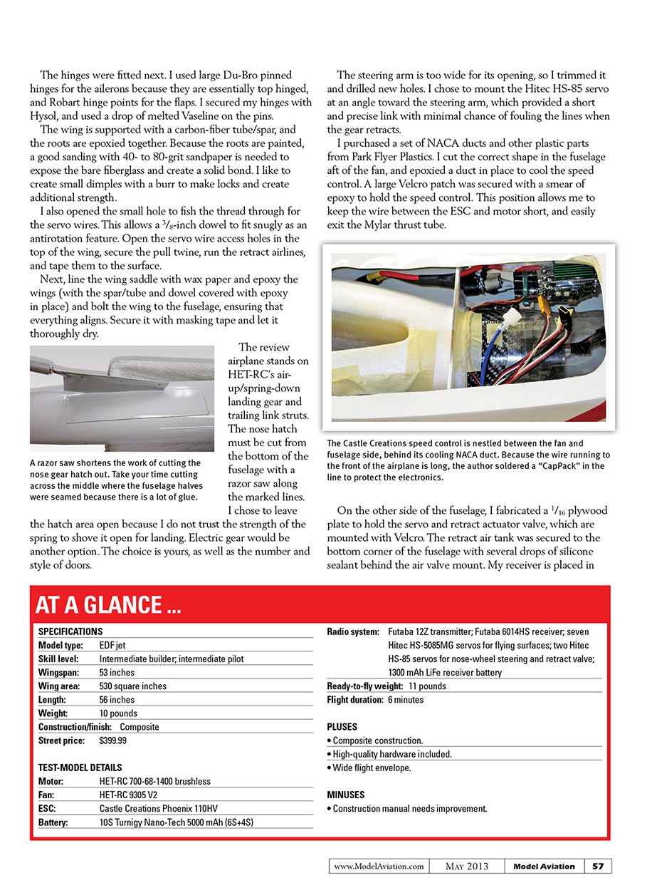
I purchased a set of NACA ducts and other plastic parts from Park Flyer Plastics. I cut the correct shape in the fuselage aft of the fan, and epoxied a duct in place to cool the speed control. A large Velcro patch was secured with a smear of epoxy to hold the speed control. This position allows me to keep the wire between the ESC and motor short, and easily exit the Mylar thrust tube.
On the other side of the fuselage, I fabricated a 1/16 plywood plate to hold the servo and retract actuator valve, which are mounted with Velcro. The retract air tank was secured to the bottom corner of the fuselage with several drops of silicone sealant behind the air valve mount. My receiver is placed in front of the fan bulkhead, between the intake and fuselage side, and secured with Velcro.
The fin presented a small challenge. There is no way for the servo mounted in the fuselage to align with the control arm without a large angle and a ball link. I created a hatch in the fin similar to what I did in the wings. I also added balsa TE to allow for more meat for the Robart hinge points.
Because I changed the servo location to enable a straight throw perpendicular to the hinge line, I had to move the control arm. I heated it with a heavy-duty soldering iron while pulling up with a pair of pliers, and the horn came free. I cut a new slot and a large amount of fiberglass millings and microballoons were mixed with Bob Smith 15-Minute Epoxy to close the original slot and secure the horn.
Two balsa blocks were provided for additional glue area and support to the fin. They were epoxied to the mount and shaped to securely fit the fin. Drill a hole large enough for the servo wire to pass through and epoxy the fin in place.
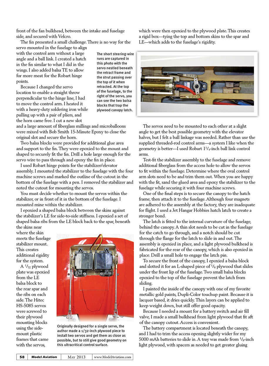
I used Robart hinge points for the stabilizer/elevator assembly. I mounted the stabilizer to the fuselage with the four machine screws and marked the outline of the cutout in the bottom of the fuselage with a pen. I removed the stabilizer and noted the cutout for mounting the servos.
You must decide whether to mount the servos within the stabilizer, or in front of it in the bottom of the fuselage. I mounted mine within the stabilizer.
I epoxied a shaped balsa block between the skins against the stabilizer's LE for side-to-side stiffness. I epoxied a set of shaped balsa ribs from the LE block back to the spar, beneath the skins near where the skin meets the fuselage stabilizer mount. This creates additional rigidity for the system.
A 1/32 plywood plate was epoxied from the LE balsa block to the rear spar and the ribs on each side. The Hitec HS-5085 servos were screwed to their plywood mounting blocks using the side-mount plastic frames that came with the servos, which were then epoxied to the plywood plate. This creates a rigid box—tying the top and bottom skins to the spar and LE—which adds to the fuselage's rigidity.
The servos need to be mounted to each other at a slight angle to get the best possible geometry with the elevator halves, but I felt a ball linkage was needed. Rather than use the supplied threaded-rod control arms—a system I like when the geometry is better—I used Robart 1 1/4-inch ball link control arms.
Test-fit the stabilizer assembly to the fuselage and remove additional fiberglass from the access hole to allow the servos to fit within the fuselage. Determine where the oval control arm slots need to be and trim them out. When you are happy with the fit, sand the glued area and epoxy the stabilizer to the fuselage while securing it with four machine screws.
One of the final steps is to secure the canopy to the hatch frame, then attach it to the fuselage. Although four magnets are adhered to the assembly at the factory, they are inadequate for flight. I used a Jet Hanger Hobbies hatch latch to create a stronger bond.
The latch is fitted to the internal curvature of the fuselage, behind the canopy. A thin slot needs to be cut in the fuselage for the catch to go through, and a notch should be cut through the flange for the latch to slide in and out. The assembly is epoxied in place, and a light plywood bulkhead is fabricated for the rear of the canopy, which is also epoxied in place. Drill a small hole to engage the latch pin.
To secure the front of the canopy, I epoxied a balsa block and slotted it for an L-shaped piece of 1/8 plywood that slides under the front lip of the fuselage. Two small balsa blocks epoxied to the top of the fuselage prevent the latch from sliding.
I painted the inside of the canopy with one of my favorite metallic gold paints, Dupli-Color touchup paint. Because it is lacquer based, it dries quickly. Thin layers can be applied to keep weight down, but still offer good opacity.
Because I needed a mount for a battery switch and air fill valve, I made a small bulkhead from light plywood that fit aft of the canopy cutout. Access is convenient.
The battery compartment is located beneath the canopy, and I had to trim the access opening slightly wider for my 5000 mAh batteries to slide in. A tray was made from 1/8-inch light plywood, with spacers as needed to get greater gluing surface and battery fit area and to allow a Velcro strap to go around it. The batteries are secured with Velcro on the floor of the tray, and on the wraparound strap.
Because it has nine servos, a 1300 mAh LiFe receiver pack is located on the tray in front of the canopy. Its accessibility allows for easy charging and balancing.
AT A GLANCE ...
SPECIFICATIONS
- Model type: EDF jet
- Skill level: Intermediate builder; intermediate pilot
- Wingspan: 53 inches
- Wing area: 530 square inches
- Length: 56 inches
- Weight: 10 pounds
- Construction/finish: Composite
- Street price: $399.99
TEST-MODEL DETAILS
- Motor: HET-RC 700-68-1400 brushless
- Fan: HET-RC 9305 V2
- ESC: Castle Creations Phoenix 110HV
- Battery: 10S Turnigy Nano-Tech 5000 mAh (6S+4S)
- Radio system: Futaba 12Z transmitter; Futaba 6014HS receiver; seven Hitec HS-5085MG servos for flying surfaces; two Hitec HS-85 servos for nose-wheel steering and retract valve; 1300 mAh LiFe receiver battery
- Ready-to-fly weight: 11 pounds
- Flight duration: 6 minutes
PLUSES
- Composite construction.
- High-quality hardware included.
- Wide flight envelope.
MINUSES
- Construction manual needs improvement.
Flying
Now for the fun part! I was able to easily balance the Sniper at the recommended CG by positioning my two battery packs on the battery tray. The recommended CG is spot-on.
The control throws are good to start with, but the throws, the amount of exponential, and the feel are individual preferences. Start with the recommended throws, and adjust as desired.
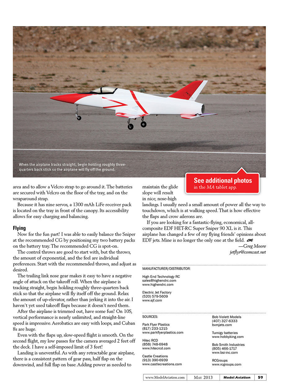
The trailing-link nose gear makes it easy to have a negative angle of attack on the takeoff roll. When the airplane is tracking straight, begin holding roughly three-quarters back stick so that the airplane will fly itself off the ground. Relax the amount of up-elevator, rather than jerking it into the air. I haven't yet used takeoff flaps because it doesn't need them.
After the airplane is trimmed out, have some fun! On 10S, vertical performance is nearly unlimited, and straight-line speed is impressive. Aerobatics are easy with loops, and Cuban 8s are huge.
Even with the flaps up, slow-speed flight is smooth. On the second flight, my low passes for the camera averaged 2 feet off the deck. I have a self-imposed limit of 3 feet!
Landing is uneventful. As with any retractable gear airplane, there is a consistent pattern of gear pass, half flap on the downwind, and full flap on base. Adding power as needed to maintain the glide slope will result in nice, nose-high landings. I usually need a small amount of power all the way to touchdown, which is at walking speed. That is how effective the flaps and crow ailerons are.
If you are looking for a fantastic-flying, economical, all-composite EDF, the HET-RC Super Sniper 90 XL is it. This airplane has changed a few of my flying friends' opinions about EDF jets. Mine is no longer the only one at the field.
— Greg Moore [email protected]
MANUFACTURER/DISTRIBUTOR
High End Technology RC [email protected] www.highendrc.com
Electric Jet Factory (520) 579-5609 www.ejf.com
SOURCES
Park Flyer Plastics (817) 233-1215 www.parkflyerplastics.com
Hitec RCD (858) 748-6948 www.hitecrcd.com
Castle Creations (913) 390-6939 www.castlecreations.com
Bob Violett Models (407) 327-6333 bvmjets.com
Turnigy batteries www.hobbyking.com
Bob Smith Industries (805) 466-1717 www.bsi-inc.com
RCGroups www.rcgroups.com
Transcribed from original scans by AI. Minor OCR errors may remain.

