
HIGH-LIFT DEVICES: FOR MODELS
Part II
A. G. Lennon
The next time you build a sport model, why not boost its realism by incorporating high-lift devices in the design? This is the conclusion of a two-part article.
One often overlooked solution to the quest for more realistic sport flying is to incorporate flaps or other high-lift devices (HLDs) in the model. Part One discussed the theory and application of HLDs for model airplanes. This concluding installment explains the design, construction, and actuation of these underappreciated devices.
The high-lift devices that I have successfully used fall into two broad categories:
- Trailing-edge slotted flaps, either internally or externally hinged
- Leading-edge devices: fixed slots or the NASA-developed leading-edge droop
Each group comprises two subcategories. What follows is a discussion of all four types of high-lift devices.
Slotted flaps
Slotted flaps must be designed so that the slot narrows steadily from the lower to the upper surface when the flap is deployed. The airflow from the slot should merge smoothly into the airflow around the wing and flap. An appreciable length of lip—the upper surface of the slot—is an advantage. Ideally, the upper contours of the wing and flap should form a smooth curve. Deployment is limited to about 40°; greater extension results in high added drag with little increase in lift.
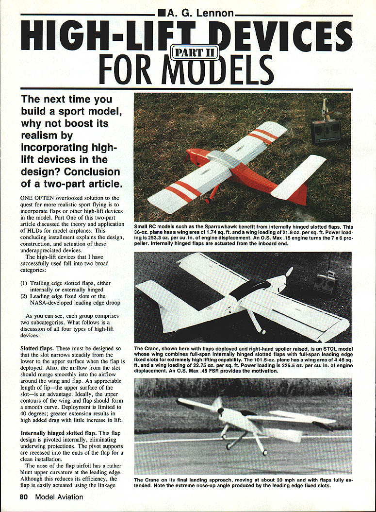
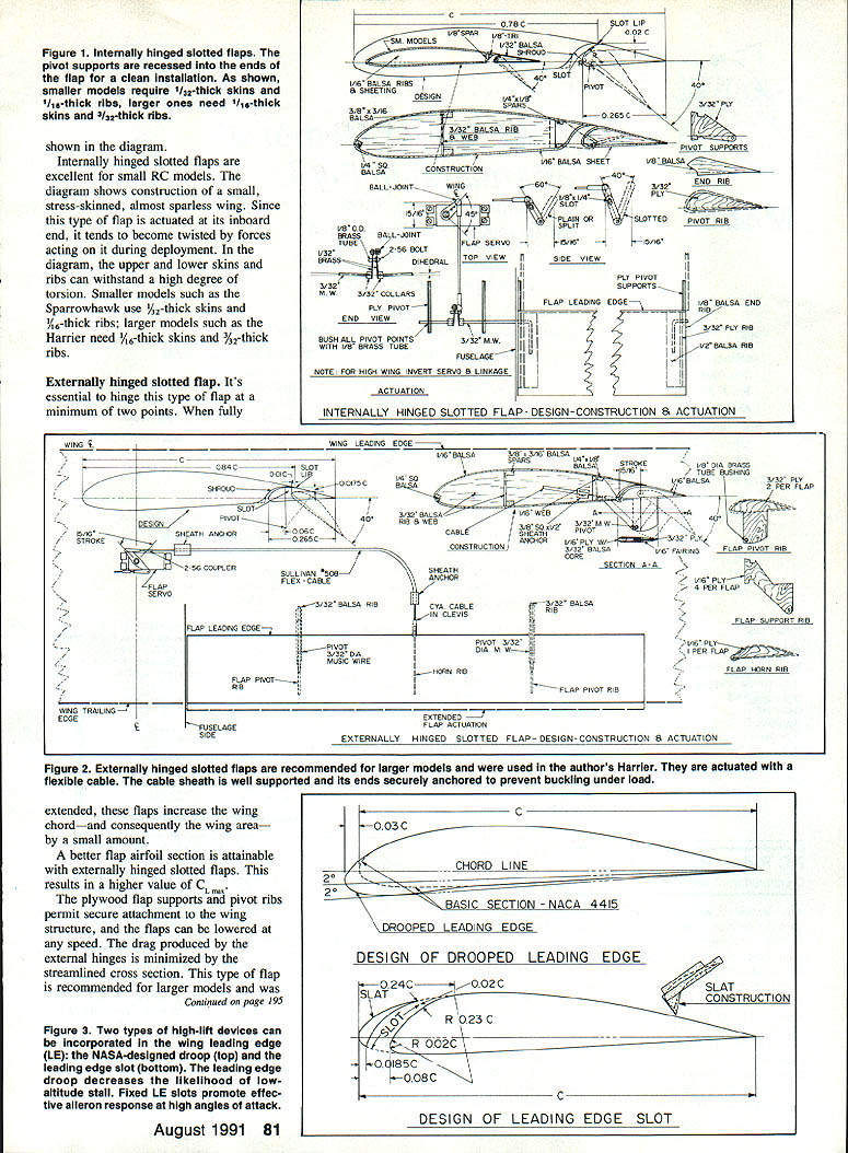
#### Internally hinged slotted flap This flap design is pivoted internally, eliminating underwing protrusions. The pivot supports are recessed into the ends of the flap for a clean installation.
The nose of the flap airfoil has a rather blunt upper curvature at the leading edge. Although this reduces its efficiency, the flap is easily actuated using the linkage. Internally hinged slotted flaps are excellent for small RC models.
The accompanying diagram shows construction of a small, stress-skinned, almost sparless wing. Since this type of flap is actuated at its inboard end, it tends to become twisted by forces acting on it during deployment. In the diagram, the upper and lower skins and ribs can withstand a high degree of torsion. Smaller models such as the Sparrowhawk use 1/32" skins and 1/16" ribs; larger models such as the Harrier need 1/8" skins and 3/32" ribs.
#### Externally hinged slotted flap It's essential to hinge this type of flap at a minimum of two points. When fully extended, these flaps increase the wing chord—and consequently the wing area—by a small amount.
A better flap airfoil section is attainable with externally hinged slotted flaps, resulting in a higher CLmax. The plywood flap supports and pivot ribs permit secure attachment to the wing structure, and the flaps can be lowered at any speed. The drag produced by the external hinges is minimized by a streamlined cross section. This type of flap is recommended for larger models.
Probably the simplest way to actuate these flaps is by a flexible cable or Nylrod, as shown in the diagram. The sort of bellcrank-and-rod arrangement that is frequently used to operate ailerons would also do the job. If using cables, be sure to anchor the sheath ends securely and support the sheath at its passage through each rib. This keeps the sheath from buckling under load.
Recommended dimensions, deflection, and maximum lift coefficient values for both types of slotted flaps:
- Fig. No. 17 — Slotted, internal hinge: percent of wing chord 25%, angle of deflection 40°, C_Lmax = 2.20
- Fig. No. 18 — Slotted, external hinge: percent of wing chord 25%, angle of deflection 40°, C_Lmax = 2.40
Leading-edge fixed slots
The fixed leading-edge slot provides an additional incremental CLmax of about 0.4 at a stall angle that is roughly 8° higher. Thus, a wing with both full-span leading-edge fixed slots and full-span internally hinged slotted flaps would generate a total CLmax of 2.20 + 0.40 = 2.60. Leading-edge slots promote effective aileron response at high angles of attack because of the acceleration of air passing through them forward of the ailerons.
Figure 3 shows the design and suggested construction of leading-edge fixed slots using balsa strips sanded to shape. Note the conical shape of the slot. Used full span on my Crane, these slots benefited the model greatly (see photo).
Leading-edge droop
This is a NASA development recently introduced in full-scale lightplanes to help prevent low-altitude stalls. As Figure 3 shows, the droop occupies the outboard 38% of the wing leading edge. The sharp corner between the drooped and undrooped portions produces a chordwise vortex that effectively separates the inner and outer panels at higher angles of attack. The drooped portion behaves like a very low aspect-ratio wing, substantially increasing both the stall angle and the effectiveness of the ailerons. This results in an additional increase of CL of about 0.2 at roughly a 10° higher angle of attack.
In flying three models incorporating the drooped leading edge, I found that while the craft sometimes entered a spin, after one or two turns the spin changed to a fast spiral dive that ended instantly when I neutralized the controls.
Calculating maximum coefficient of lift (CLmax) for combinations
The maximum coefficient of lift for any combination of high-lift devices can be determined with a few easy calculations.
- The flapped areas will develop the CLmax given in the table above when the flaps are fully lowered. Do not adjust these figures for the increase in wing area produced by the flaps; that has already been done.
- The unflapped areas will generate the CLmax of the basic wing airfoil.
- For leading-edge slots, add a lift increment of 0.4 to the basic section values.
- Add 0.2 for the drooped leading edge.
Example — Harrier wing:
- Flapped wing area: 356 sq. in. × CL of 2.40 = 854.4
- Unflapped area with drooped leading edge: 220 sq. in. × (CLmax 1.2 + 0.2) = 220 × 1.4 = 308
- Total area: 576 sq. in.
- Total lift (sum): 854.4 + 308 = 1162.4
- Total CLmax = 1162.4 ÷ 576 = 2.02
Trim considerations
Because of the increased lift and drag they induce and the increase in nose-down (negative) pitching moment, all types of flaps cause a marked change in trim when deployed. It is recommended that elevators comprising at least 40% of the horizontal tail-plane area be installed to counter this pitching action and permit flaring the model as it touches down in ground effect.
Try slotted flaps on your next model. They'll add realism of performance and appearance. You'll have a better-looking craft that gives you more fun and variety in the air.
Transcribed from original scans by AI. Minor OCR errors may remain.

