
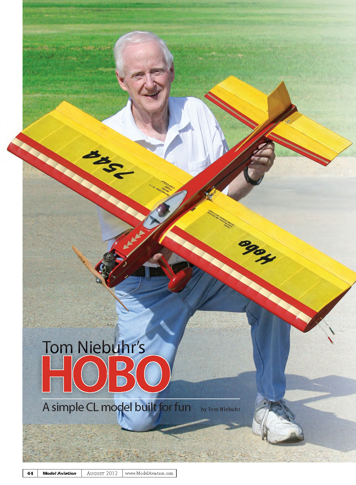
Tom Niebuhr's HOBO
A simple CL model built for fun
by Tom Niebuhr
Many have told me they were not ready for a full-bodied airplane, yet in most cases profile airplanes were holding up their progress. Many of the available profile kits are simply recreations of airplanes from the 1950s with thin airfoils and short moments. This is nostalgic, but does not present an ideal platform. A twisting, vibrating fuselage does nothing to help engine runs or the aerodynamic capabilities of the airplane. A simple airplane is needed to provide the step up from the profiles.
Although I thrive on competing in Stunt with the best equipment available (see Top Hat in the March 2009 Flying Models, and the Jerseyan in the September 2004 MA), I need a fun airplane as a relief from the days of hard practice—an airplane that will address all of the previous criteria.
I realize most people are not interested in the demanding practice sessions required for top-level competition. Even those who might regularly attend contests and strive to improve their flying skills might not be interested in campaigning at an expert level. From that idea the Hobo was born.
In the last 20 to 25 years there has been little attention given to building a full-bodied fun airplane. No airplane has been designed with the Hobo’s options. This is a sport airplane, but is it really enough? Visualize a multipurpose airplane capable of performing the CL Stunt pattern, but offering much more. It doesn’t have to be pretty. It must have a full fuselage to avoid vibration and twisting exhibited with profile layouts. It must be simple for fast construction.
I wanted an airplane with capabilities that may not have been addressed in the past: a convertible airplane with a changeable appearance. I encourage kitbashing! It must be capable of quick-change control ratios and line sweep, allowing for sane and insane maneuvers, from extremely tight loops to the Sabre Dance. It should be capable of performing the Stunt pattern or any maneuver you can imagine. All of this should be packaged with the simplicity of a monoplane.
The Hobo can be built with many variables. The controls can be internal, or installed with an old-style external pushrod that allows easy transition of the elevator-to-flap ratio from the standard one-to-one to the excessive elevator movement that accommodates wild maneuvers. The wing sheeting is minimal for simple, fast construction. The wingtips are flat, allowing the inboard one to have a simple slot for a wingtip slider that can be adjusted for Stunt trim or moved aft for crazy Hobo maneuvers. The outboard wingtip has a blind nut installed to accept additional external weight. No blocks are used in the fuselage. The engine is upright and uncowled. The nose allows for tank changes and adjustments.
The Hobo is a multipurpose, convertible airplane that does not require six months or more to build. It is a simple step up from a profile, providing a better aerodynamic platform for Intermediate or Advanced competition or just plain fun.
Fuselage
The top of the fuselage sides has only a short segment parallel to the thrustline. The plans show tabs used so the fuselage can be assembled upside down; the tabs are cut off after the basic fuselage sides and formers are installed.
Most tanks are slightly wider than 2 inches, requiring the end caps to be squeezed in a vise. The Hobo’s nose is 1/32 inch wider than the standard 2 inches to allow the fuel tank to slide in. The F-1 and F-2 plywood formers have tabs that key into the fuselage, ensuring the engine mounts are properly aligned.
Use a long straightedge to align the top of the fuselage building tabs, then glue the forward and rear fuselage sides together. Next, glue the 1/32-inch plywood doublers in place. Make one left-hand and one right-hand doubler.
Make the engine crutch and trim the balsa spacers to fit between plywood formers F-1 and F-2. Leave at least 1/8 inch of the engine mounts at the aft end to extend through F-2. The tank shelf (F-3) fits into slots in the fuselage to ensure proper alignment of the engine mounts. (Note: the engine mounts can be drilled for the engine before the crutch is installed.)
Install the crutch and plywood formers F-1 through F-3 onto one fuselage side. Use a 90° triangle to make sure all parts are perpendicular to the fuselage side. When the glue has dried, position the fuselage upside down on the building tabs and install the other fuselage side. Using the notches and tabs, the parts snap into place. The basic fuselage can be built in one day. I recommend using 30-minute or 1-hour epoxy for installing the 1/32 doublers, engine mounts, and all plywood parts.
When the nose parts are dry, use a centerline drawn on your table or a fuselage jig to align the fuselage sides, and install the remaining balsa formers. Do not remove the building tabs at this time.
Wing
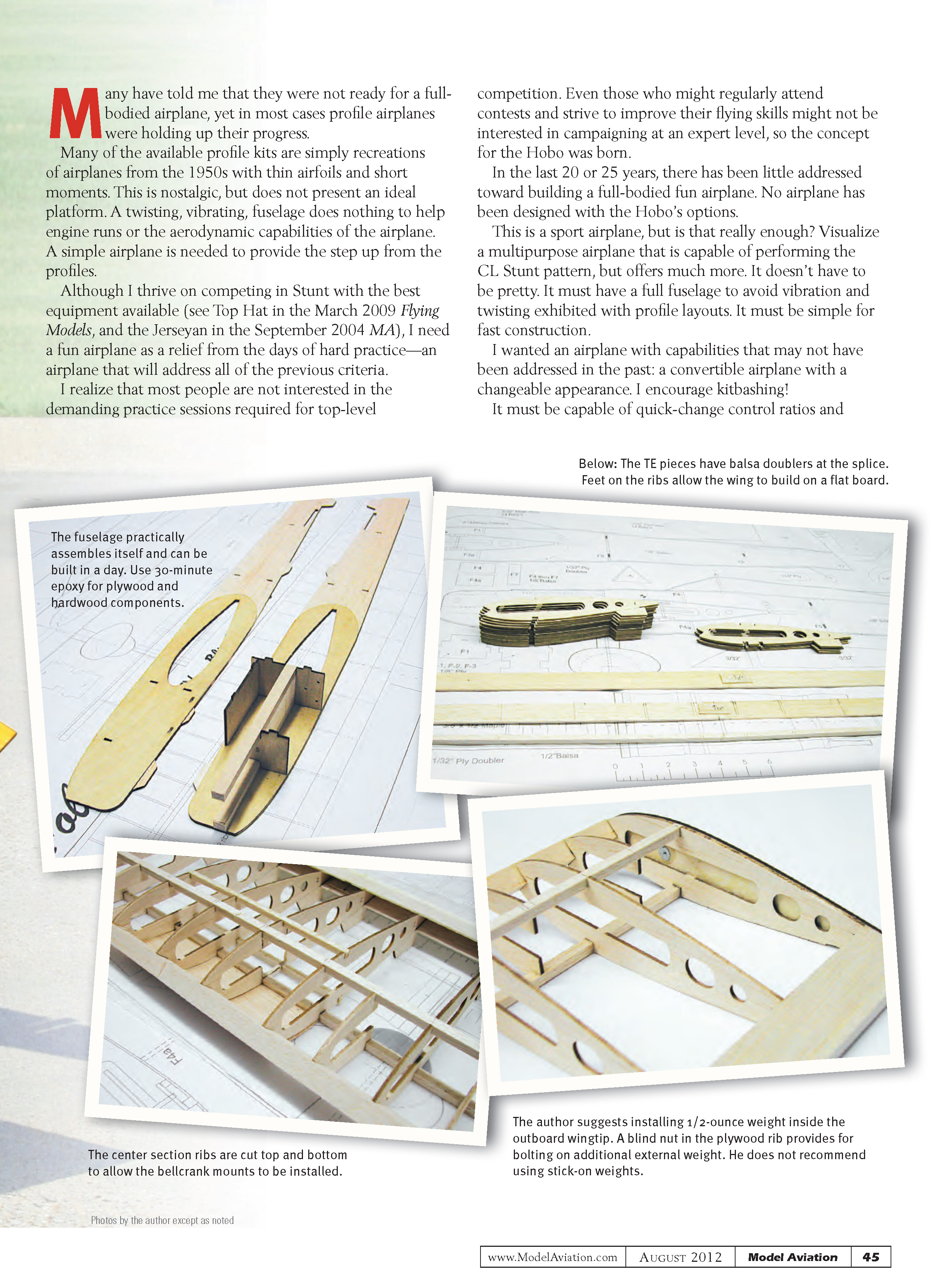
The Hobo’s wing can be assembled in one evening. Laser-cut ribs are available from Blue Sky Models. Splice the spars and TEs as shown on the plans, and mark the rib locations on the spars and TE.
Place the ribs onto the 1/4-inch spars but do not glue them into place. Use a long straightedge at the rear of the rib jigging feet to make sure the wing’s TE will be straight and ensure the ribs are vertical and 90° to the spars and TE. Using thin CA, attach each rib to the lower TE and the main spars. Use cotton swabs to wipe away excess glue before it sets.
Check the alignment and glue the LE and main 1/4-inch spars in place along with the lower 3/16-inch center spar and the top TE sheet. Use aliphatic glue and masking tape to install the 1/4-inch TE cap. Turn the wing over and install the 3/32-inch center section sheeting. Don’t remove the rib jigging feet at this time.
The 1/4-inch spars will be flush with the center section sheeting. I advise placing light weights over the ribs during assembly to ensure the wing remains straight. Use care installing the half ribs—they are delicate until glued into place.
Controls and wingtips
You can choose internal or external controls, which is a unique feature of the Hobo. External controls allow easy control-ratio adjustment for competition-type maneuvers or outlandish fun maneuvers.
The inner center rib must be trimmed slightly to allow installation of the bellcrank mount on top of the 1/4-inch and 3/16-inch lower spars. Install the upper center section’s 3/16-inch spar, complete the bellcrank-to-flap controls, and install the upper center section sheeting.
Install the inboard 1/8-inch light plywood wingtip rib and slider. Then install a 4-40 blind nut on the inside of the outboard 1/8-inch light plywood wingtip. I suggest permanently installing approximately 1/2 ounce of weight inside the outboard wingtip. Final weight can be added externally using bolt-on weights available from Sig Manufacturing or Brodak Manufacturing. Trim and sand the LE and TE caps to shape to complete the wing.
Assembly
If you are using external controls, the fuselage can slide onto the wing. If you choose internal controls you can place the fuselage upside down on the building tabs, cut out a section of the fuselage to install the wing, and then replace the cutout sections.
If you cut the fuselage, install internal 1/32-inch plywood doublers across the slice. These can be made from scrap and should extend 1 inch at each side of the joint. I suggest making wingtip jigs to help ensure the wing is installed square into the fuselage.
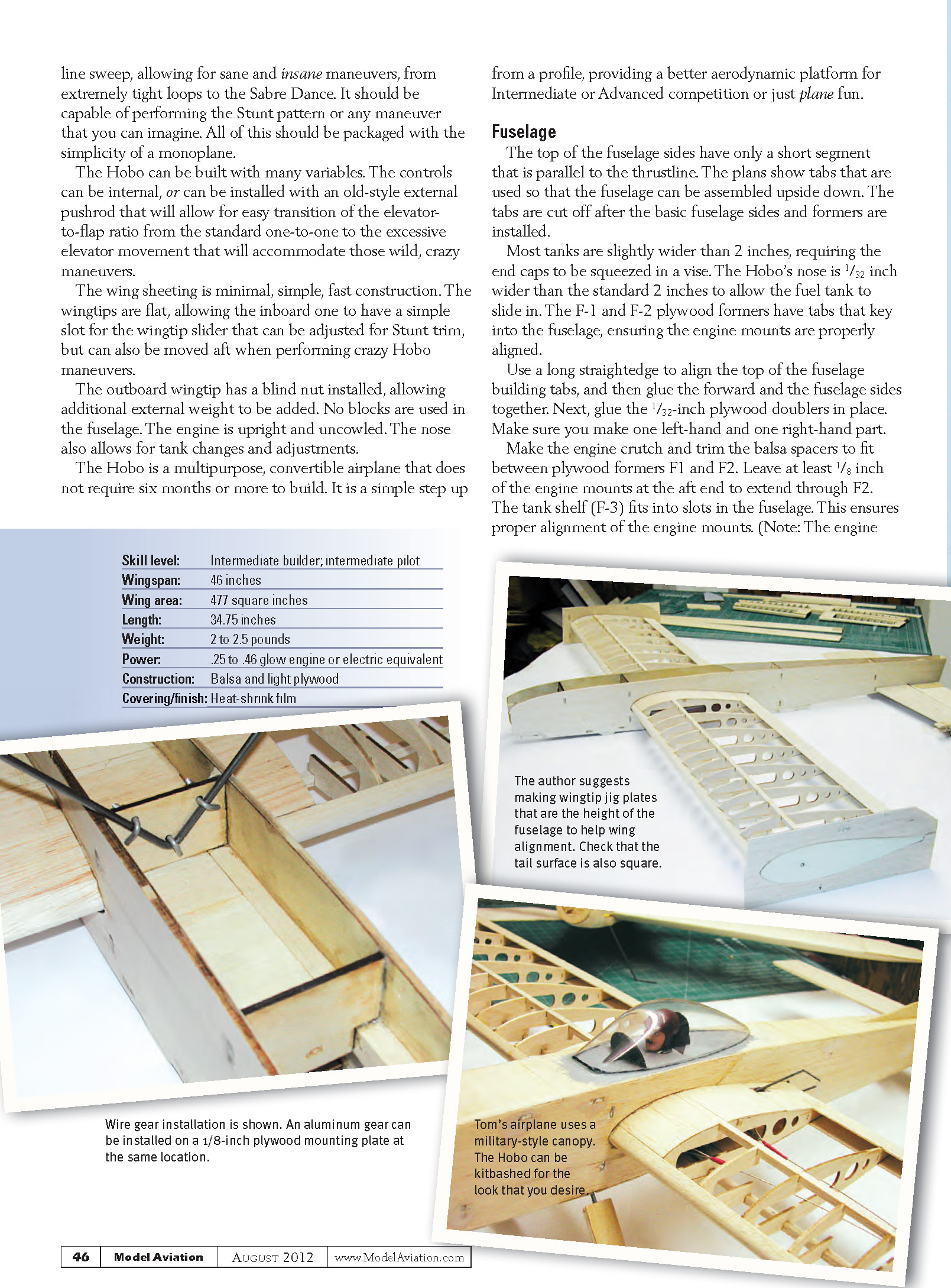
Use either a 1/8-inch wire landing gear installed with J-bolts or .093-inch aluminum gear. A 1/8-inch plywood plate is made and two sets of blind nuts can be installed so the gear can be moved forward for grass applications. Installing wheel pants is easier with the aluminum gear. Install a 6-32 blind nut in the plywood pant clip, and use a jam nut on the inside of the landing gear. The forward fuselage side view on the plans shows this installation.
The LEs and TEs of the flaps, stabilizer, and elevator are sanded round. Double- and triple-check alignments while installing the tail surfaces, and then install the tail wheel mount.
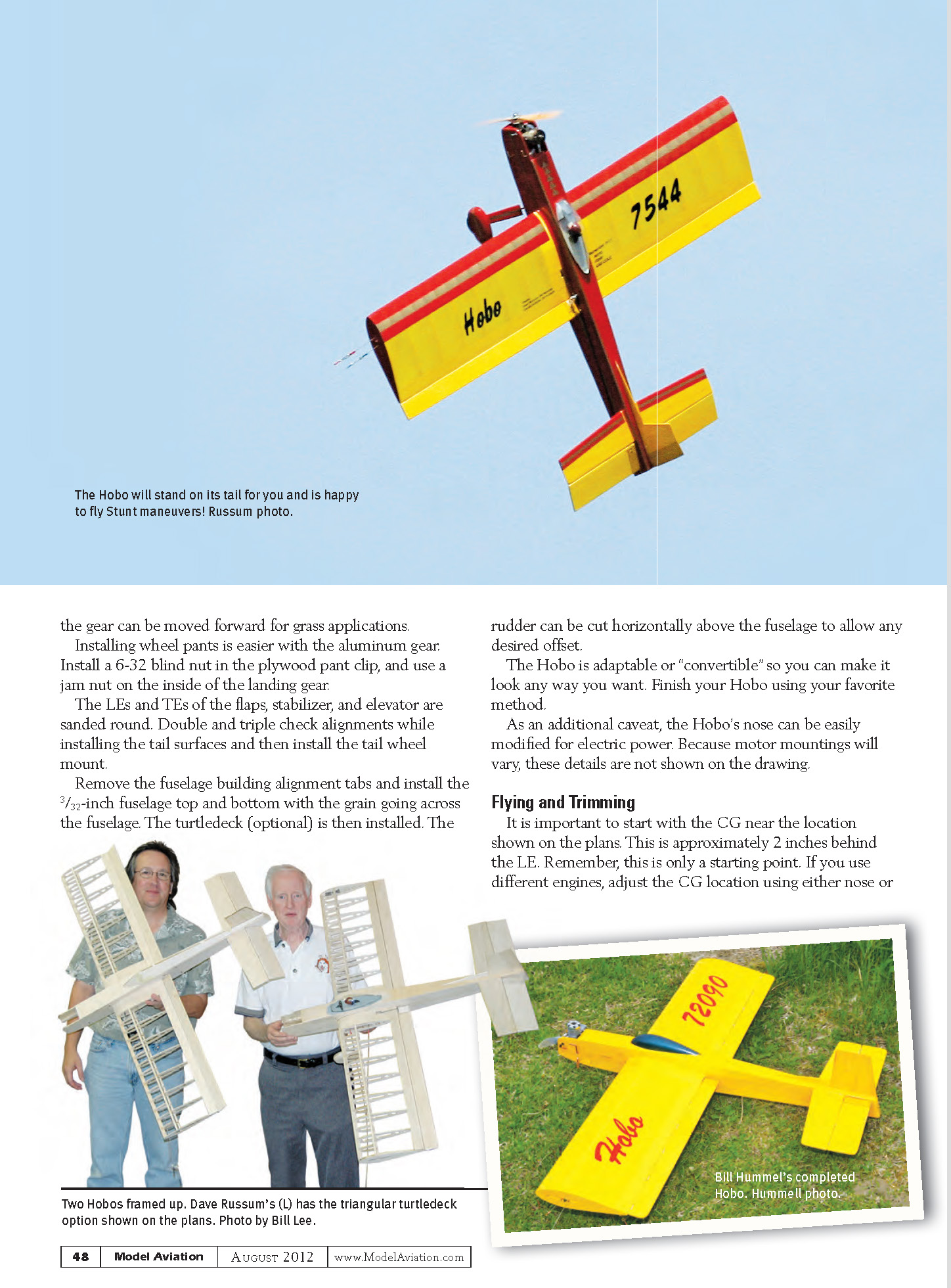
Remove the fuselage building alignment tabs and install the 3/32-inch fuselage top and bottom with the grain going across the fuselage. The turtledeck (optional) is then installed. The rudder can be cut horizontally above the fuselage to allow any desired offset.
The Hobo is adaptable or "convertible" so you can make it look any way you want. Finish your Hobo using your favorite method.
As an additional caveat, the Hobo's nose can be easily modified for electric power. Because motor mountings will vary, these details are not shown on the drawing.
Flying and Trimming
Start with the CG near the location shown on the plans—approximately 2 inches behind the LE. This is only a starting point; if you use different engines, adjust the CG location using either nose or tail ballast.
The author suggests installing 1/2 ounce of weight inside the outboard wingtip. A blind nut in the plywood rib provides for bolting on additional external weight. He does not recommend using stick-on weights.
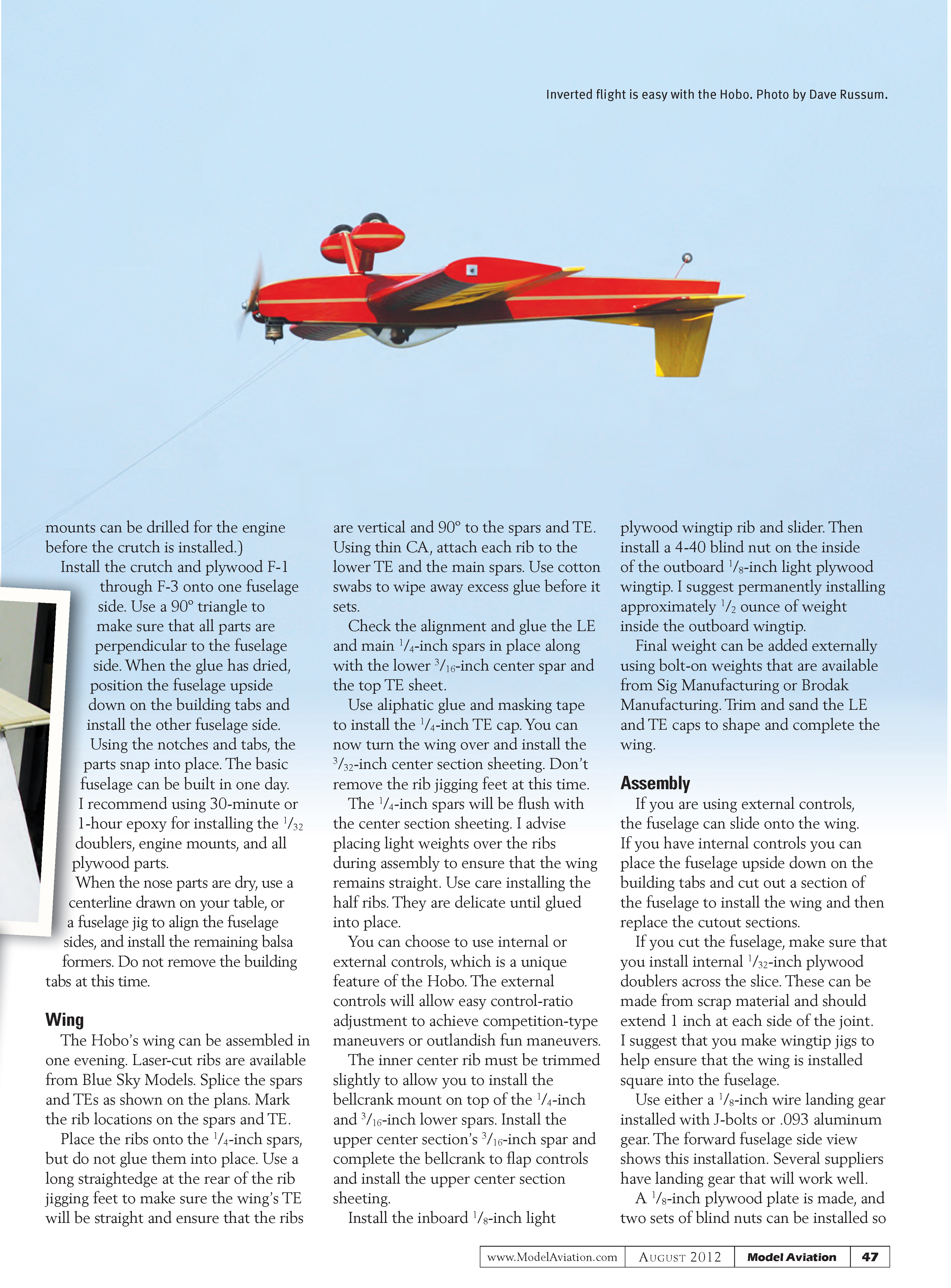
The centerline sweep allows for a wide range of maneuvers, from extremely tight loops to the Sabre Dance. The Hobo should be capable of performing the Stunt pattern or any maneuver you can imagine. Quick-change control ratios and line sweep let you go from sane to wild maneuvers.
There are many methods of adding nose weight. Examples include:
- Prather-type weights installed on the engine shaft
- Harry Higley aluminum and brass propeller nuts
- Tongue- or tube-type mufflers
- Adding weight under the engine
Adjusting tail weight can be as simple as using different size tail wheels.
The prototype Hobos have been test beds for several different engines. For easy tailweight adjustments on those prototypes I cut a square section out of the inboard side of the fuselage under the elevator, then installed a 4-40 post bolt on a 1/8-inch plywood plate on the inside of the outboard fuselage side. This allows bolt-on weights to be installed on the 4-40 post and held in place with a 4-40 locknut. I reinstalled the square cutout as a hatch cover held in place with clear packing tape.
Start with about 1/2 ounce of additional weight outside the wingtip and then adjust as required. For novelty maneuvers, the leadouts should be farther aft; additional wingtip weight is generally recommended.
Hobos using Fox .35s or Double Star .40s generally have the CG range close to the desired location. Nearly all airplanes require adjustments in line sweep, wingtip weight, and forward or aft CG.
Hobos have also been flown with various line lengths. Engines in the .25 or .35 size might require shorter lines in the 55-foot range; larger engines might require longer lines. Handle line spacing is another trim consideration—if the airplane is happy but slightly sensitive, reduce the line spacing at the handle.
In Conclusion
I want to thank Bill Hummel, Dave Russum, and Gerald Schamp for help with the prototype airplanes and photographs. Here is Bill's assessment of his prototype Hobo:
"I flew eight more flights with the Hobo on Wednesday—all full patterns. The ship continues to perform admirably!
"Using both the Double Star .40 plain bearing and a souped-up Fox 35, the Hobo performs all the tricks nicely! I also did a little fooling around with some maneuvers not in the book ... this little guy has character to spare, and will do anything you ask of it! Reminds me of a terrier we once had—no fear, and all attitude!
"I don't believe I would change anything on future versions. It's a sweet ship to fly! Thanks again for a really nice and innovative design, Tom!"
—Tom Niebuhr [email protected]
SOURCES
- Brodak Manufacturing
(724) 966-2726 or (724) 966-9131 www.brodak.com
- Blue Sky Models
(469) 487-1256 www.blueskymodels.net
- Sig Manufacturing
(641) 623-5154 www.sigmfg.com
Transcribed from original scans by AI. Minor OCR errors may remain.

