


Hotchek
C. Brent Dane
Hotchek is a small, easy-to-build device based on the LM3914 voltage-measurement integrated circuit (IC) and can be used to measure the output voltage of rechargeable battery packs. A built-in discharge circuit places a 300 mA load on the battery that can be activated by the press of a button. The application of this load is very important, since the stability of the battery's voltage under current drain is an important indication of its charge state.
Hotchek's small size and weight allow it to be installed onboard an RC vehicle, or it can be used as a "pocket-sized" battery checker. Component values are provided for four- and five-cell Ni-Cd receiver packs, as well as for eight-cell transmitter packs. A simple set of formulas is presented to adjust the voltage range for other battery testing applications, including 12 V lead-acid field batteries.
The rechargeable Ni-Cd batteries that we use to power our equipment have fairly flat discharge curves; they deliver their stored energy (charge) with only a moderate reduction in output voltage. This allows our radio transmitter, receiver, and servos to operate near full power between battery charging.
The disadvantage comes when one wants to determine how much of the remaining stored charge is available in the pack. Since the voltage doesn't dramatically decrease as the battery charge is exhausted, it is not necessarily a simple matter to determine the state of charge of the battery pack by measuring its voltage.
The capacity of a rechargeable battery (or battery pack) is generally specified in milliampere-hours (mAh). Typical Ni-Cd or NiMH (nickel metal hydride) cells range in capacity from 250 to more than 2,000 mAh.
The most reliable way to determine the amount of stored energy in a battery pack is to completely discharge it—sometimes referred to as cycling. If the pack is discharged at constant current, the capacity can be calculated by multiplying the discharge rate in milliamperes by the discharge time in hours. For Ni-Cd batteries, the discharge time is usually defined as the time required for each cell to reach a voltage of 1.1 V.
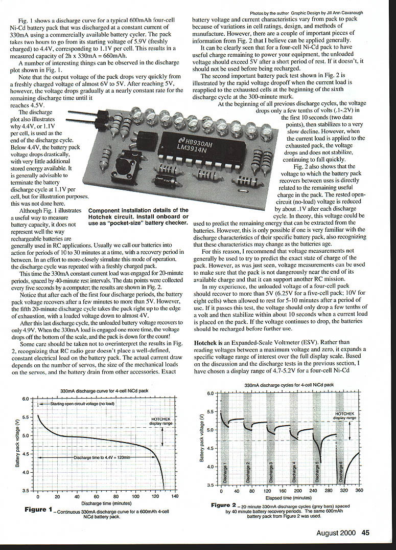
A number of interesting things can be observed in the discharge plot shown in Fig. 1.
Note that the output voltage of the pack drops very quickly from a freshly charged voltage of almost 6 V to 5 V. After reaching 5 V, however, the voltage drops gradually at a nearly constant rate for the remaining discharge time until it reaches 4.5 V.
The discharge plot also illustrates why 4.4 V, or 1.1 V per cell, is used as the end of the discharge cycle. Below 4.4 V, the battery pack voltage drops drastically, with very little additional stored energy available. It is generally advisable to determine the battery discharge cycle at 1.1 V per cell, but for illustration purposes, this was not done here.
Although Fig. 1 illustrates a useful way to measure battery capacity, it does not represent well the way rechargeable batteries are generally used in RC applications. Usually we call our batteries into action for periods of 10 to 30 minutes at a time, with a recovery period in between. In an effort to more closely simulate this mode of operation, the discharge cycle was repeated with a freshly charged pack.
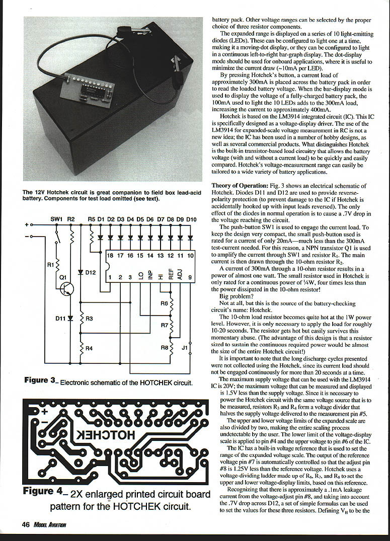
This time the 330 mA constant-current load was engaged for 20-minute periods, spaced by 40-minute rest intervals. The data points were collected every five seconds by a computer; the results are shown in Fig. 2.
Notice that after each of the first four discharge periods, the battery pack voltage recovers after a few minutes to more than 5 V. However, the fifth 20-minute discharge cycle takes the pack right up to the edge of exhaustion, with a loaded voltage down to almost 4 V.
After this last discharge cycle, the unloaded battery voltage recovers to only 4.9 V. When the 330 mA load is engaged one more time, the voltage drops off the bottom of the scale, and the pack is down for the count!
Some care should be taken not to overinterpret the results in Fig. 2, recognizing that RC radio gear doesn't place a well-defined, constant electrical load on the battery pack. The actual current draw depends on the number of servos, the size of the mechanical loads on the servos, and the battery drain from other accessories. Exact battery voltage and current characteristics vary from pack to pack because of variations in cell ratings, design, and methods of manufacture. However, there are a couple of important pieces of information from Fig. 2 that I believe can be applied generally.
It can be clearly seen that for a four-cell Ni-Cd pack to have useful charge remaining to power your equipment, the unloaded voltage should exceed 5 V after a short period of rest. If it doesn't, it should not be used before being recharged.
The second important battery pack test shown in Fig. 2 is illustrated by the rapid voltage dropoff when the current load is reapplied to the exhausted cells at the beginning of the sixth discharge cycle at the 300-minute mark.
At the beginning of all previous discharge cycles, the voltage drops only a few tenths of volts in the first 10 seconds (two data points), then stabilizes to a very slow decline. However, when the current load is applied to the exhausted pack, the voltage drops and does not stabilize, continuing to fall quickly.
Fig. 2 also shows that the voltage to which the battery pack recovers between uses is directly related to the remaining useful charge in the pack. The rested open-circuit (no-load) voltage is reduced by about 0.1 V after each discharge cycle. In theory, this voltage could be used to predict the remaining energy that can be extracted from the batteries. However, this is only possible if one is very familiar with the discharge characteristics of their specific battery pack, also recognizing that these characteristics may vary with the battery's age.
For this reason, I recommend that voltage measurements not generally be used to try to predict the exact state of charge of the pack. However, as was just seen, voltage measurements can be used to make sure that the pack is not dangerously near the end of its available charge and that it can support another RC mission.
In my experience, the unloaded voltage of a four-cell pack should recover to more than 5 V (6.25 V for a five-cell pack; 10 V for eight cells) when allowed to rest for 5–10 minutes after a period of use. If it passes this test, the voltage should only drop a few tenths of a volt and then stabilize within about 10 seconds when a current load is placed on the pack. If the voltage continues to drop, the batteries should be recharged before further use.
Hotchek is an expanded-scale voltmeter (ESV). Rather than reading voltages between a maximum voltage and zero, it expands a specific voltage range of interest over the full display scale. Based on the discussion and the discharge tests in the previous section, I have chosen a display range of 4.7–5.2 V for a four-cell Ni-Cd battery pack and 5.7–6.2 V for a five-cell Ni-Cd pack. This allows the meter to show small changes in the useful operating range of the pack so that the user can quickly determine whether a pack is safe to use or should be recharged.
Other voltage ranges can be selected by the proper choice of three resistor components.
The expanded range is displayed on a series of 10 light-emitting diodes (LEDs). These can be configured to light one at a time, making it a moving-dot display, or they can be configured to light in a continuous left-to-right bar-graph display. The dot-display mode should be used for onboard applications, where it is useful to minimize the current draw (~10 mA per LED).
By pressing Hotchek's button, a current load of approximately 300 mA is placed across the battery pack in order to read the loaded battery voltage. When the bar-display mode is used to display the voltage of a fully charged battery pack, the 100 mA used to light the 10 LEDs adds to the 300 mA load, increasing the current to approximately 400 mA.
Hotchek is based on the LM3914 integrated circuit (IC). This IC is specifically designed as a voltage-display driver. The use of the LM3914 for expanded-scale voltage measurement in RC is not a new idea; the IC has been used in a number of hobby designs, as well as several commercial products. What distinguishes Hotchek is the built-in transistor-based load circuitry that allows the battery voltage (with and without a current load) to be quickly and easily compared. Hotchek's voltage-measurement range can easily be tailored to a wide variety of battery applications.
Theory of Operation
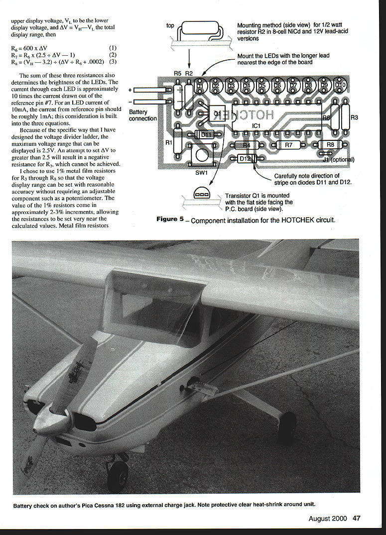
Fig. 3 shows an electrical schematic of Hotchek. Diodes D11 and D12 are used to provide reverse-polarity protection (to prevent damage to the IC if Hotchek is accidentally hooked up with input leads reversed). The only effect of the diodes in normal operation is to cause a 0.7 V drop in the voltage reaching the circuit.
The push-button SW1 is used to engage the current load. To keep the design very compact, the small push-button used is rated for a current of only 20 mA—much less than the 300 mA test current needed. For this reason, an NPN transistor Q1 is used to amplify the current through SW1 and resistor R1. The main current is then drawn through the 10-ohm resistor R2.
A current of 300 mA through a 10-ohm resistor results in a power of almost one watt. The small resistor used in Hotchek is only rated for a continuous power of 1/4 W, four times less than the power dissipated in the 10-ohm resistor!
Big problem?
Not at all, but this is the source of the battery-checking circuit's name: Hotchek.
The 10-ohm load resistor becomes quite hot at the 1 W power level. However, it is only necessary to apply the load for roughly 10–20 seconds. The resistor gets hot but easily survives this momentary abuse. (The advantage of this design is that a resistor sized to sustain the continuous required power would be almost the size of the entire Hotchek circuit!)
It is important to note that the long discharge cycles presented were not collected using the Hotchek, since its current load should not be engaged continuously for more than 20 seconds at a time.
The maximum supply voltage that can be used with the LM3914 IC is 20 V; the maximum voltage that can be measured and displayed is 1.5 V less than the supply voltage. Since it is necessary to power the Hotchek circuit with the same voltage source that is to be measured, resistors R3 and R4 form a voltage divider that halves the supply voltage delivered to the measurement pin #5.
The upper and lower voltage limits of the expanded scale are also divided by two, making the entire scaling process undetectable by the user. The lower limit of the voltage-display scale is applied to pin #4 and the upper voltage to pin #6 of the IC. The IC has a built-in reference that is used to set the range of the expanded voltage scale. The output of the reference voltage pin #7 is automatically controlled so that the adjust pin #8 is 1.25 V less than the reference voltage. Hotchek uses a voltage-dividing ladder made up of R6, R7, and R8 to set the upper and lower voltage-display limits, based on this reference.
Recognizing that there is approximately a 0.1 µA leakage current from the voltage-adjust pin #8, and taking into account the 0.7 V drop across D12, a set of simple formulas can be used to set the values for these resistors. Defining Vh to be the upper display voltage, Vl to be the lower display voltage, and ΔV = Vh − Vl, the total display range, then:
R5 = 600 × ΔV
R7 = R6 × (2.5 ÷ ΔV − 1)
R8 = (Vl − 3.2) ÷ (ΔV ÷ R6 + 0.0002)
The sum of these three resistances also determines the brightness of the LEDs. The current through each LED is approximately 10 times the current drawn out of the reference pin #7. For an LED current of 10 mA, the current from reference pin #7 should be roughly 1 mA; this consideration is built into the three equations.
Because of the specific way that I have designed the voltage-divider ladder, the maximum voltage range that can be displayed is 2.5 V. An attempt to set ΔV to greater than 2.5 V will result in a negative resistance for R7, which cannot be achieved.
I chose to use 1% metal-film resistors for R3 through R8 so that the voltage display range can be set with reasonable accuracy without requiring an adjustable component such as a potentiometer. The value of the 1% resistors come in approximately 2–3% increments, allowing the resistances to be set very near the calculated values.
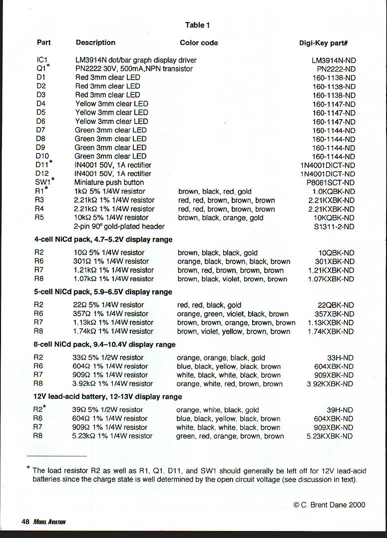
Parts (Table 1)
- IC1: LM3914N dot/bar graph display driver — Digi-Key: LM3914N-ND
- Q1*: PN2222 30 V, 500 mA, NPN transistor — PN2222-ND
- D1–D10: LEDs
- D1–D3: Red 3 mm clear LED — 160-1138-ND
- D4–D6: Yellow 3 mm clear LED — 160-1147-ND
- D7–D10: Green 3 mm clear LED — 160-1144-ND
- D11*: 1N4001 50 V, 1 A rectifier — 1N4001DICT-ND
- D12: 1N4001 50 V, 1 A rectifier — 1N4001DICT-ND
- SW1*: Miniature push button — P8081SCT-ND
- R1*: 1 kΩ 5% 1/4 W resistor — 1.0KQBK-ND (brown, black, red, gold)
- R3: 2.21 kΩ 1% 1/4 W resistor — 2.21KXBK-ND
- R4: 2.21 kΩ 1% 1/4 W resistor — 2.21KXBK-ND
- R5: 10 kΩ 5% 1/4 W resistor — 10KQBK-ND
- 2-pin 90° gold-plated header — S1311-2-ND
4-cell NiCd pack, 4.7–5.2 V display range:
- R2: 10 Ω 5% 1/4 W resistor — 10QBK-ND (brown, black, black, gold)
- R6: 301 Ω 1% 1/4 W resistor — 301XBK-ND
- R7: 1.21 kΩ 1% 1/4 W resistor — 1.21KXBK-ND
- R8: 1.07 kΩ 1% 1/4 W resistor — 1.07KXBK-ND
5-cell NiCd pack, 5.9–6.5 V display range:
- R2: 22 Ω 5% 1/4 W resistor — 22QBK-ND
- R6: 357 Ω 1% 1/4 W resistor — 357XBK-ND
- R7: 1.13 kΩ 1% 1/4 W resistor — 1.13KXBK-ND
- R8: 1.74 kΩ 1% 1/4 W resistor — 1.74KXBK-ND
8-cell NiCd pack, 9.4–10.4 V display range:
- R2: 33 Ω 5% 1/2 W resistor — 33H-ND
- R6: 604 Ω 1% 1/4 W resistor — 604XBK-ND
- R7: 909 Ω 1% 1/4 W resistor — 909XBK-ND
- R8: 3.92 kΩ 1% 1/4 W resistor — 3.92KXBK-ND
12 V lead-acid battery, 12–13 V display range:
- R2*: 39 Ω 5% 1/2 W resistor — 39H-ND
- R6: 604 Ω 1% 1/4 W resistor — 604XBK-ND
- R7: 909 Ω 1% 1/4 W resistor — 909XBK-ND
- R8: 5.23 kΩ 1% 1/4 W resistor — 5.23KXBK-ND
Notes:
- The load resistor R2 as well as R1, Q1, D11, and SW1 should generally be left off for 12 V lead-acid batteries since the charge state is well determined by the open-circuit voltage.
© C. Brent Dane 2000
Construction
Table 1 is a complete parts list, with the Digi-Key Electronics catalog numbers. Fig. 4 is a 2× enlarged pattern for the printed circuit board. Those interested in building a circuit but who do not want to manufacture a PC board may contact the author; a complete unassembled kit can also be obtained (a complete unassembled kit for the etched PC board is $10).
The best way to make this board is with a product called Press-n-Peel, manufactured by Techniks. It is a blue plastic film that can be run through a conventional photocopy machine or printed onto directly with a laser printer.
Following the instructions supplied with the film, the image in Fig. 4 should be copied onto the dull side with 50% reduction. It is then ironed onto a copper-clad board (Radio Shack 276-1499) using a household or sealing iron.
When experimenting to find the best temperature, I find it useful to securely tape the film to the board along one edge. I then carefully peel back a small portion to test the adhesion of the pattern to the board. If the transfer is incomplete, the film is let back down and additional pressure and higher temperature used.
After successful image transfer, the board is etched in a solution of ferric chloride (Radio Shack 276-1535) for 30–60 minutes or until all of the unwanted copper is gone. Note that the blank board is two-sided, so the copper will be completely removed from the back side.
After etching, the mounting holes should be drilled with a #65 drill bit. Fig. 5 shows a diagram of the installation of the components onto the board. They should be inserted from the side opposite from the copper circuit pattern. Table 1 is a list of the components with their required values.
Special attention should be given to L1, Q1, and D1–D12, since the direction they are installed is very important. The LEDs often have a small flat on one side that should be oriented as shown in Fig. 5. If the LEDs don't have the flat, the positive lead (upper lead in the figure) can be identified by the fact that it is longer than the negative lead. Diodes D11 and D12 have a stripe identifying one of the leads.
I have found that LEDs with clear lenses are most visible in sunlight conditions. However, note that it is not possible to distinguish among the three colors until they are installed in the circuit and operating. For this reason, take care not to lose track of which color LED is which.
The 1% metal-film resistors are blue with five color bands. The last band is always brown, indicating 1%, and is spaced a bit farther from the other four bands to identify it. I find that the color of the bands is sometimes difficult to make out against the blue background, so good lighting and patience is suggested here. I often resort to confirming the resistances with a digital multimeter.
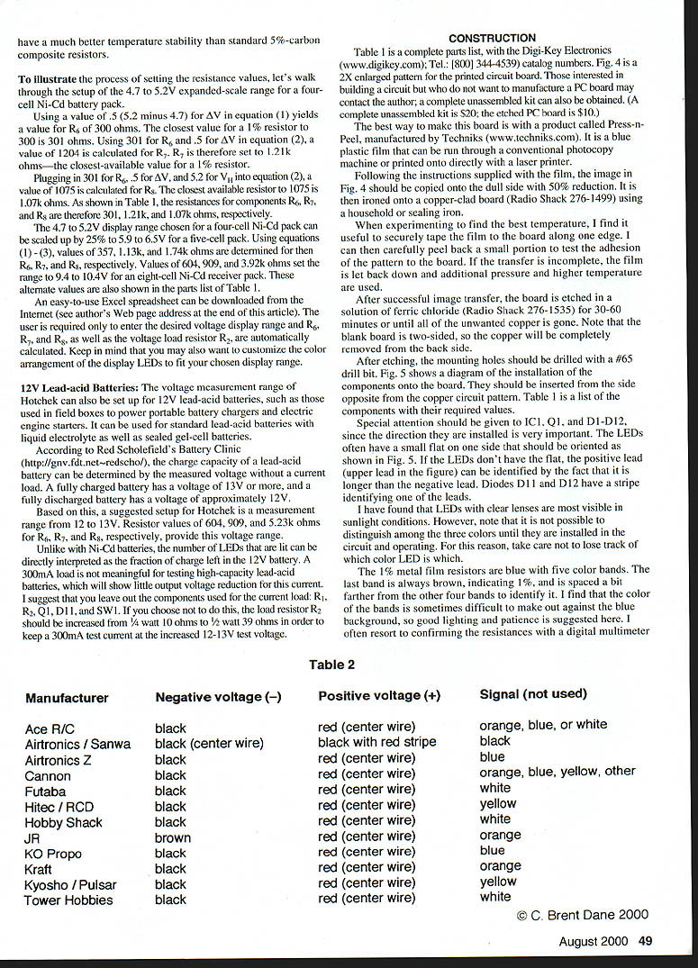
Servo Wire Color Codes (Table 2)
Manufacturer - Negative voltage (–) - Positive voltage (+) - Signal (not used)
- Ace R/C: black - red (center wire) - orange, blue, or white
- Airtronics / Sanwa: black (center wire) - black with red stripe - black
- Airtronics Z: black - red (center wire) - blue
- Cannon: black - red (center wire) - orange, blue, yellow, other
- Futaba: black - red (center wire) - white
- Hitec / RCD: black - red (center wire) - yellow
- Hobby Shack: black - red (center wire) - white
- JR: brown - red (center wire) - orange
- KO Propo: black - red (center wire) - blue
- Kraft: black - red (center wire) - orange
- Kyosho / Pulsar: black - red (center wire) - yellow
- Tower Hobbies: black - red (center wire) - white
Users of older Airtronics equipment should be cautioned that the V+ and V− wires are reversed in the servo harness from those for Futaba, JR, and RCD radio systems. Since the Airtronics harness has two wires of the same color (black), carefully note which one is the center wire in Table 2.
Optional jumper J1 can be made from a short piece of trimmed resistor lead. If J1 is left out, the display will be a single moving-dot display. If J1 is installed, the bar mode is activated.
Carefully solder the installed components to the copper circuit pattern, taking care to avoid solder bridges across gaps between the traces. It is extremely important to use a good-quality resin-core electronics-grade solder, and to brighten the copper traces with fine steel wool or a Scotchbrite pad before starting. Advice and/or instruction from a fellow modeler with circuit assembly experience could be useful here.
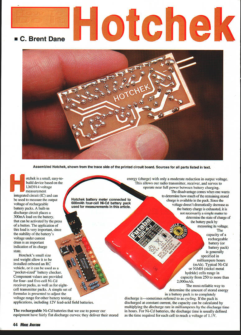
A photo shows the completed soldering job on the trace side of the board. The excess resin left from soldering can be easily removed with a solvent such as lacquer thinner, and an epoxy brush with the bristles cut back to 1/4 inch.
A 90° two-pin header can be used for the input voltage as shown. As an alternate for onboard applications, a servo wiring harness can be soldered into the board so that Hotchek can be plugged directly into the receiver. Using Fig. 5, carefully attach the leads according to the chart above.
For onboard installations, you may want to omit the current-loading circuitry (R1, R2, Q1, D11, and SW1) to prevent possible binding against the test button and accidental engagement of the test load during operation of the RC vehicle. As previously discussed, the loading section of the circuit also has little utility for 12 V lead-acid batteries, and can be omitted.
Using Hotchek
Hotchek can be used as a very compact handheld ESV or as a voltage monitor mounted in the RC vehicle. Remove jumper J1 to minimize current draw for onboard installations. It is often very useful to watch the onboard voltage display while the servos and other onboard equipment are exercised before a flight.
For the "pocket ESV" approach, I like to insert Hotchek into a short length of one-inch clear heat-shrink tubing to protect the circuit. Care should be exercised not to overheat the components when shrinking. After shrinking, a small hole can be cut through the covering over the test button, using the sharpened end of a 3/16-inch diameter brass tube. The prongs from Hotchek's 90° header can be easily inserted into the external charging jack on the RC vehicle to check the battery voltage.
As is shown in Fig. 2, the open-circuit voltage (no load) of a four-cell Ni-Cd receiver pack should be at least 5 V (6.25 V for five cells). One of the four green LEDs, or at least the rightmost yellow LED, should be lit.
When the 300 mA load is engaged, the voltage should drop by one to two LEDs, then stabilize within about 10 seconds. It is important to note that there is the possibility of voltage losses through the receiver battery wiring harness and connectors onboard the RC vehicle. These losses could cause another 0.1 V or more drop when the load is engaged.
If the voltage drop due to the battery wiring harness is excessive with a freshly charged pack, this may indicate that shorter leads to the battery or heavier-gauge wire is required. In this case Hotchek is helping to identify a separate problem from a simple case of a discharged battery pack.
It is not unusual for the display range to be as far as one LED in error in one direction or the other. Since there are no adjustable components, small variations in component values can cause this small offset. The major source of possible errors is the result of variations in the leakage current from the reference adjust pin #8 on the LM3914.
If you would like to fine-tune the display range, adjust resistor R3 up to the next available value to raise the display range, or down to the next available value to make a small adjustment downward. However, if you choose not to do this, a small offset should not cause problems in using Hotchek as a general battery diagnostic tool for comparing the unloaded and loaded battery voltage. In practice, I have found that the component values shown in Table 1 produce acceptable results.
Does it sound like Hotchek is the ultimate answer for all of your battery-checking needs? If so, you may have missed something and should go back and carefully read this article again.
The use and maintenance of rechargeable batteries is a challenging task, and there is no single magic bullet to prevent battery-related RC failures. The most important thing you can do is to know the behavior of your specific battery packs, and carefully monitor them before, during, and after use. Hotchek can be a very valuable tool for helping you to do this.
I also strongly suggest that the condition of your packs be checked on a regular basis with a good-quality commercial battery cycler. Remember: your safety, as well as the safety of others, depends on the health of the batteries that power your RC equipment.
MA
C. Brent Dane 678 Crane Ave. Livermore, CA 94550 [email protected] http://home.pacbell.net/cbdare
Transcribed from original scans by AI. Minor OCR errors may remain.

