
How to Adjust That High-Powered AMA Gas Free Flight
Illustrations by Jim Newman
This extraordinary two-part series is based upon interviews with top fliers. This installment deals with the nature of the machine and the many factors which govern its performance. The fun part comes next month . . . — Ralph Prey
Two words sum it all up . . . "Very Carefully." Experienced competition-minded free-flight fliers, representing untold numbers and hours of flight testing, echo these words. "Very Carefully." I'd like to share with you this experience, and much-needed know-how, to help you adjust high-powered, high-performance models. Whether you're a sport flier or already competition-minded, if you understand the aerodynamic theory and apply the construction and adjusting techniques, you'll be spared traumatic test flights, fatal crashes, and even improve the caliber of your competitive flying.
To begin with, let's put the problem in perspective. What is a high-powered, high-performance AMA Gas free-flight model? High-powered refers to the engine. For example, it has features such as Schnuerle porting; ABC (aluminum-bronze-chrome) piston and sleeve; uses fuels containing more than 50% nitromethane; operates only on a pressure fuel system; no muffler; and turns in excess of 20,000 rpm. High performance refers to the model's climb and glide, which is consistently capable of maxing out in dead air. AMA Gas refers to the AMA Gas classes, such as A, B, C, etc., for free-flight models, flown according to the free-flight categories with either 2-, 3-, or 5-minute maxes.
Let's also face the fact that a high-powered, high-performance free-flight model is more demanding than earlier generation free-flight models. Consider, too, that a model of this type has characteristics such as:
- A very fast steep climb.
- Responds very quickly to the slightest adjustment.
- Is less forgiving to unnoticed minor warps or misalignment.
- Critical with regard to center of gravity location on the plans compared to actual construction.
- Requires quick DT for flight testing.
- May require auto-rudder, or auto-stabilizer, or both.
As you ponder what adjustments to make, you will see there's a lot at stake to achieve a better climb or glide. In the final analysis, before you can logically proceed to adjust your new-generation model, you must understand basic aerodynamic theory. Also try to anticipate the model's flight paths, and build in adjustments to control the anticipated flight paths.
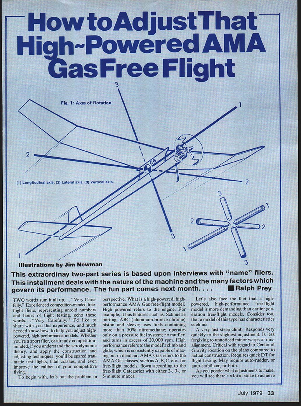
Aerodynamically, the model flies around three axes of rotation that pass through the center of gravity (CG, or balance point) of the model. These axes of rotation are known as the Longitudinal, Lateral, and Vertical axis (Fig. 1).
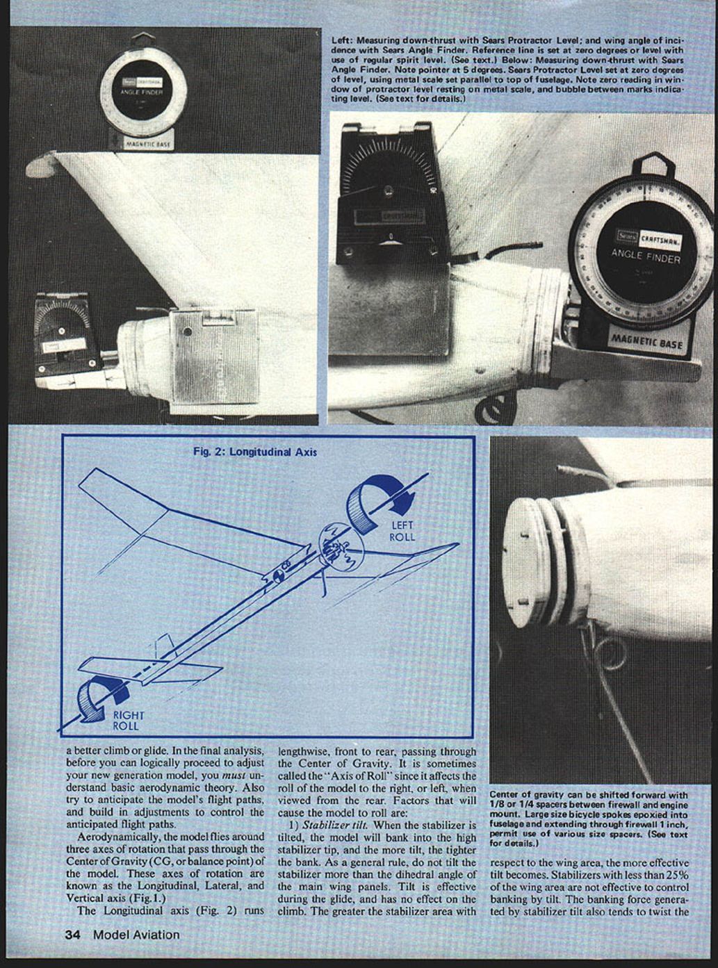
Longitudinal axis (Fig. 2)
The longitudinal axis runs lengthwise, front to rear, passing through the center of gravity. It is sometimes called the "axis of roll" since it affects the roll of the model to the right or left when viewed from the rear. Factors that will cause the model to roll are:
- Stabilizer tilt.
- When the stabilizer is tilted, the model will bank into the high stabilizer tip, and the more tilt, the tighter the bank.
- As a general rule, do not tilt the stabilizer more than the dihedral angle of the main wing panels.
- Tilt is effective during the glide, and has no effect on the climb.
- The greater the stabilizer area with respect to the wing area, the more effective tilt becomes. Stabilizers with less than 25% of the wing area are not effective to control banking by tilt.
- The banking force generated by stabilizer tilt also tends to twist the fuselage. Therefore, the fuselage must be built rigid to resist twisting, which could change the effectiveness of the stabilizer tilt.
- Wing tilt.
- Wing tilt tends to roll the model into the high wing tip and is used to trim the glide circle, particularly when only a very small increase in turn is desired.
- Wing wash-in or wash-out.
- A wing panel has wash-in when it is twisted so that the trailing edge is lower than the leading edge. Wash-in increases lift on that panel, causing the model to roll away from the washed-in panel. For example, when viewed from the rear, if the right main wing panel is washed-in, the model will roll to the left.
- The amount and rate of roll depend upon the degree of wash-in and the speed of the model. The more wash-in, the more roll. As speed increases, the rate of roll increases; conversely, as speed decreases, lift decreases and the rate of roll decreases.
- Wash-out is the opposite: the trailing edge is higher than the leading edge, reducing lift and causing the model to roll into the washed-out wing panel. The amount and rate of roll depend on the degree of wash-out and the model speed.
- The most generally accepted method of controlling the right roll caused by propeller slipstream is with wash-in or wash-out on a main wing panel. Preferably, wash-in or wash-out should be built into the main wing panel during construction, rather than twisting or warping with heat after covering and doping. Warping after covering affects the wing tip panel, which must then be warped back to its former position.
- To build in wash-in into the right main wing panel, place shims of the desired thickness (e.g., 3/32", 1/8") under the leading edge at the outboard dihedral joint. Then proceed as usual with ribs, spars, etc.
- As a general practice, wash-out is used in both wing tip panels to improve wing stall characteristics and reduce drag in the glide caused by the wing tips. Wash-out should be built into the tip panels during construction: shim up the trailing edge of the tip panel to the desired thickness and complete as usual.
- Stabilizer wash-in or wash-out.
- Like wing wash-in, stabilizer wash-in will cause the model to roll away from the wash-in. Stabilizer wash-out will cause the model to roll into the washed-out side. Speed affects the amount of roll; as speed increases, the roll increases.
- Propeller slipstream.
- On a right-hand-rotating propeller, when viewed from the rear, slipstream tends to bank the model to the right. The slipstream effect increases as engine rpm increases. Slipstream effect is greater on a pylon model than on a high-thrust model.
- Propeller torque.
- Torque is the reactive force generated by the turning propeller that tends to revolve the model opposite to the direction of rotation of the propeller. On a conventional glow engine with a right-hand-rotating propeller, when viewed from the rear, the propeller torque tends to roll the model to the left. As engine rpm increases, torque also increases.
- Propeller pitch affects propeller torque. As the pitch or blade angle is increased, propeller torque also increases.
- Cocking the wing off perpendicular to the centerline of the pylon, or placing the wing asymmetrically on the pylon.
- Cocking the wing so that one side leads the other will tend to roll the model into the trailing wing half.
- Placing the wing off center on the pylon, so that one side has more area than the other, will tend to roll the model into the wing half with less area.
- Wing heaviness.
- The wing should be balanced so that both sides are equal in weight. If one side is heavier than the other, the model will tend to roll into the heavy side.
Dutch roll
- Dutch roll describes a rolling followed by a yaw to the right, a stable return taking it past neutral into a yaw and roll to the left in pendulum fashion. Dutch roll is caused by insufficient rudder area and too much dihedral.
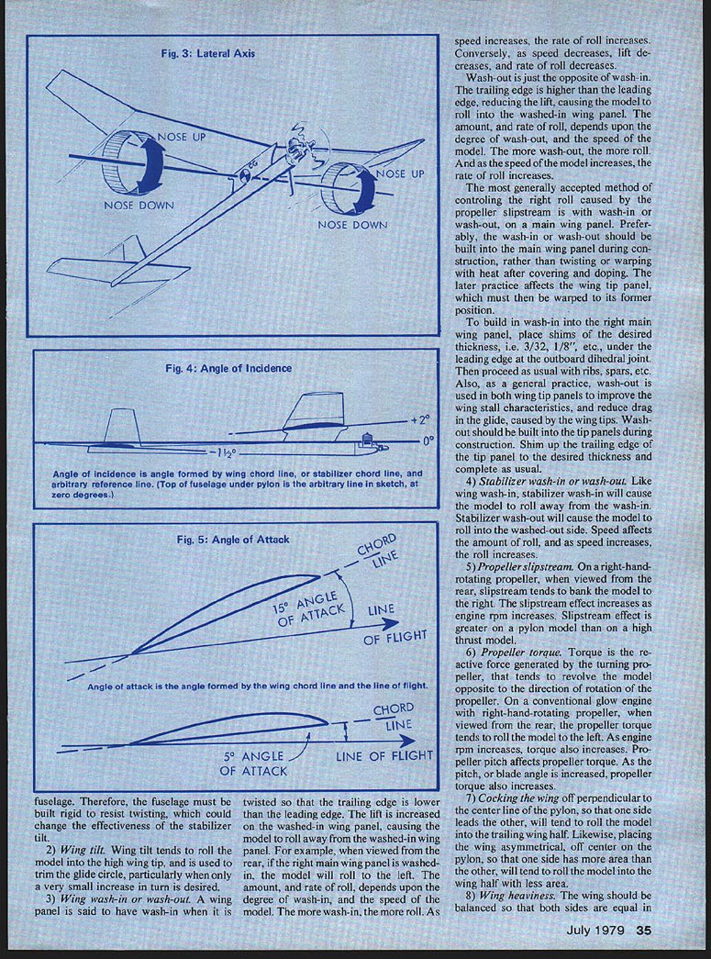
Lateral axis (Pitch)
The lateral axis runs wingtip to wingtip, passing through the center of gravity. It is sometimes called the "pitch" axis. Factors that affect pitching (nose up or down) behavior include:
- Center of Gravity (balance point) location.
- Since the three axes of rotation pass through the center of gravity, its location is the single most important point in the model.
- Under power, the farther forward the CG (toward the leading edge of the wing), the more the model will tend to nose up. Conversely, the farther rearward the CG (toward the trailing edge), the more the model will tend to nose down.
- In a glide, the opposite effects occur: the farther forward the CG, the more the model will tend to nose down; the farther rearward, the more the model will tend to nose up.
- For this reason, do not attempt to flight test the model until the location of the CG is exactly as shown on the plans.
- The CG can be found by balancing the completely assembled model on the index fingers placed under a wing rib on each side of the wing mount. It may be necessary to add weight to the tail or nose to bring the CG to the exact location on the plans.
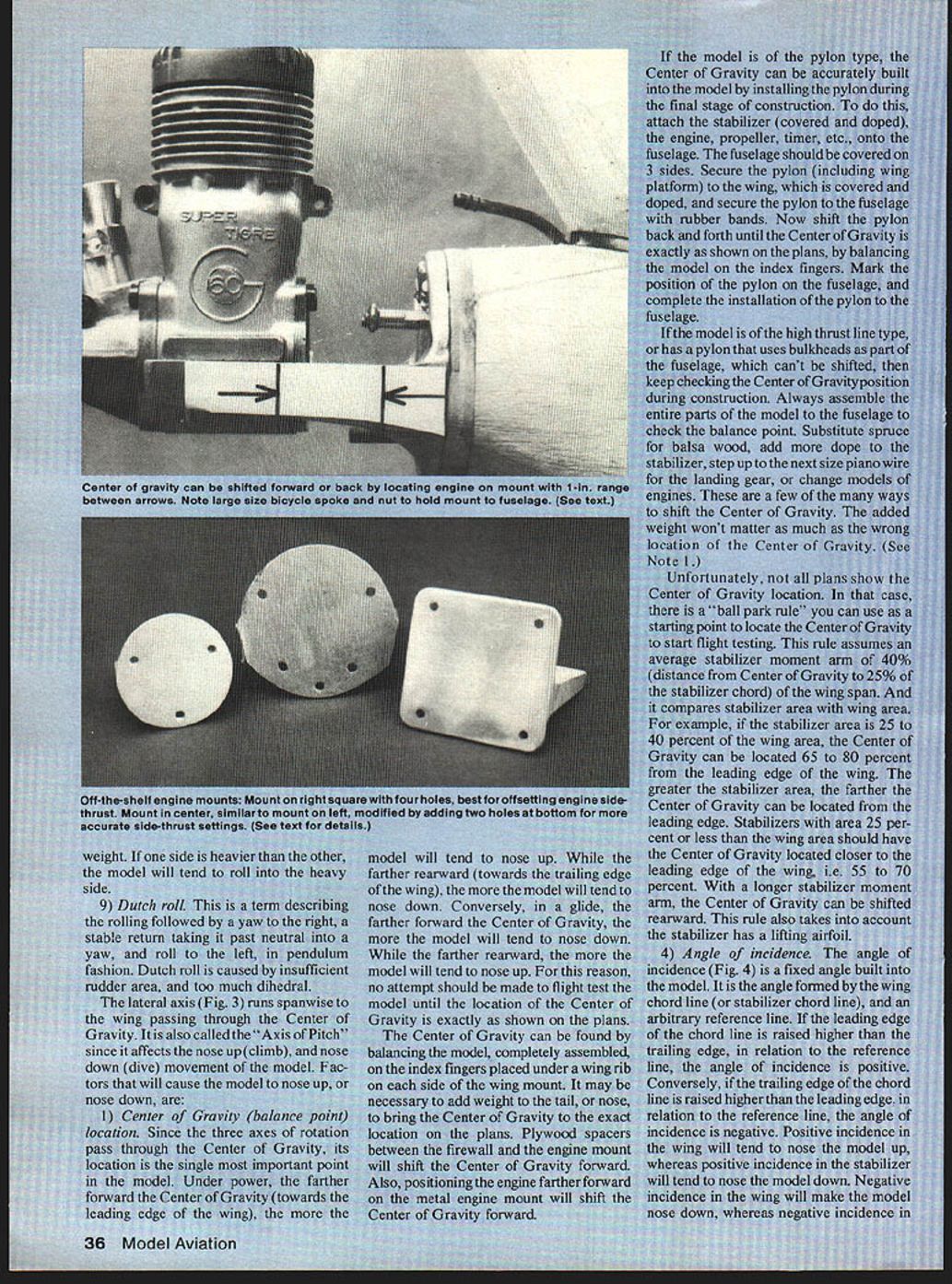
- Plywood spacers between the firewall and the engine mount will shift the CG forward. Also, positioning the engine farther forward on the metal engine mount will shift the CG forward.
- If the model is of the pylon type, the CG can be accurately built into the model by installing the pylon during final construction: attach the stabilizer (covered and doped), the engine, propeller, timer, etc., to the fuselage (covered on three sides). Secure the pylon (including wing platform) to the wing and secure the pylon to the fuselage with rubber bands. Shift the pylon back and forth until the CG is exactly as shown on the plans by balancing the model on the index fingers. Mark the pylon position on the fuselage and complete the installation.
- If the model is of the high-thrust-line type or has a pylon that uses bulkheads as part of the fuselage (which can't be shifted), keep checking the CG position during construction. Always assemble the entire parts of the model to the fuselage to check the balance point. Substitute spruce for balsa, add more dope to the stabilizer, step up to the next size piano wire for the landing gear, or change engine models. These are a few ways to shift the CG. The added weight won't matter as much as the wrong CG location.
Ballpark rule for CG when plans don't show it:
- This rule assumes an average stabilizer moment arm (distance from CG to 25% of the stabilizer chord) of 40% of the wing span and compares stabilizer area with wing area.
- If stabilizer area is 25–40% of wing area, locate the CG 65–80% from the leading edge of the wing. The greater the stabilizer area, the farther aft the CG can be.
- Stabilizers with area 25% or less of wing area should have the CG closer to the leading edge (about 55–70%).
- With a longer stabilizer moment arm, the CG can be shifted rearward. This rule assumes the stabilizer has a lifting airfoil.
- Decalage.
- Decalage is the angular difference between the wing and stabilizer. The greater the angular difference, the more the model will tend to nose up; conversely, the less the angular difference, the more the model will tend to nose down.
- Angle of incidence.
- The angle of incidence is a fixed angle built into the model. It is the angle formed by the wing chord line (or stabilizer chord line) and an arbitrary reference line (for convenience, often the top of the fuselage under the pylon is used as zero degrees).
- If the leading edge is raised higher than the trailing edge relative to the reference, the incidence is positive; if the trailing edge is higher, incidence is negative.
- Positive incidence in the wing will tend to nose the model up, whereas positive incidence in the stabilizer will tend to nose the model down. Negative incidence in the wing makes the model nose down, whereas negative incidence in the stabilizer makes it nose up.
- Key point when changing stabilizer incidence, especially when tilt is used in the stabilizer for glide turn: removing shims from under the trailing edge also removes some of the turn; adding shims under the leading edge also increases the turn.
- Engine down-thrust and up-thrust.
- Down- or up-thrust, when viewed from the side, is the angle formed by the thrust line (centerline of the crankshaft) and an arbitrary reference line.
- If the thrust line points down (negative angle), it causes the nose to go down. If it points up (positive angle), it causes the nose to go up.
- Engine power.
- Increased engine power will cause the model to nose up depending on CG location. If the CG is too far back, increased power may tend to nose the model down into a dive. If the CG is too far forward, increased power will cause the nose to go up.
- Stabilizer airfoil section.
- If the stabilizer shape is similar to the wing airfoil, the stabilizer will generate lift. Airfoil thickness and shape determine lift characteristics.
- As a general rule, stabilizer airfoil thickness should be less than the wing airfoil thickness, and not more than about 2% difference. For example, if the wing airfoil thickness is 10% of the wing chord, the minimum stabilizer thickness should be about 8% of the stabilizer chord.
- Angle of attack (Fig. 5).
- Angle of attack is the angle formed by the wing chord line and the line of flight. It changes according to wing attitude relative to the line of flight and determines the amount of lift.
- As angle of attack increases, lift increases until the stall angle. Angle of attack should not be confused with angle of incidence—the two have different reference lines (line of flight vs. an arbitrary fixed reference).
- Pylon height and thrust line position.
- Lowering the pylon height or raising the thrust-line position produces the same effect: reducing nose-up tendency during the climb.
- Raising the pylon height or lowering the thrust-line position tends to increase the nose-up attitude.
- Stabilizer position in relation to wing downwash.
- Positioning the stabilizer in the wing downwash will cause the model to nose up in the climb because the downwash strikes the top surface of the stabilizer, forcing the stabilizer down and the nose up.
- The longer the stabilizer moment arm (distance from the wing), the less effective downwash becomes on the stabilizer. For this reason, a smaller stabilizer size can be used with a long moment arm.
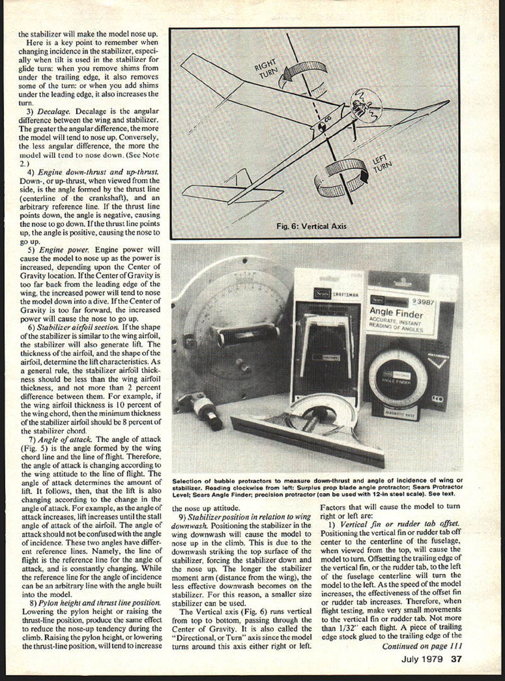
Vertical axis (Fig. 6)
The vertical axis runs vertical, top to bottom, passing through the center of gravity. It is also called the "directional" or "yaw" axis since the model turns around this axis either right or left. Factors that will cause the model to turn right or left:
- Vertical fin or rudder tab offset.
- Positioning the vertical fin or rudder tab off center of the fuselage centerline, when viewed from the top, will cause the model to turn.
- Offsetting the trailing edge of the vertical fin or rudder tab to the left of the fuselage centerline will turn the model left.
- As model speed increases, the effectiveness of the offset fin or rudder tab increases. Therefore, during flight testing make very small movements of the vertical fin or rudder tab (use 1/32" flight-piece stock glued to the trailing edge).
- A piece of trailing-edge stock glued to the trailing edge of the tab near the top of the vertical fin will tend to cause a rolling effect around the longitudinal axis as well as a turn, and thereby may not achieve the desired results.
- Right-or-left engine thrust.
- Right- or left-thrust, when viewed from the top, is the angle formed by a line drawn lengthwise through the center of the crankshaft and measured either right or left of the fuselage centerline.
- Cocking the engine thrust line off center will cause the model to turn in the direction of the engine thrust line.
- Engine thrust offset is effective at low speeds; as speed increases, thrust offset becomes less effective. For this reason, thrust offset is used primarily to control the initial part of the climb, and vertical fin or rudder tab offset is used to control the remainder of the power climb.
Stability
Finally, the model must have stability. Without stability around each axis of rotation it is doomed to self-destruction. Stability is the ability of the model to resist changes from normal flight and the ability, when upset by an outside force (such as a gust), to recover and return to normal flight. The designer of the model determined certain stability factors, such as dihedral angle and size of stabilizer and vertical fin. You, too, must decide certain stability factors, such as angles of incidence of wing and stabilizer, amount of rudder-tab offset, engine-thrust offset, etc. You have a vital role in the eventual stability of the model.
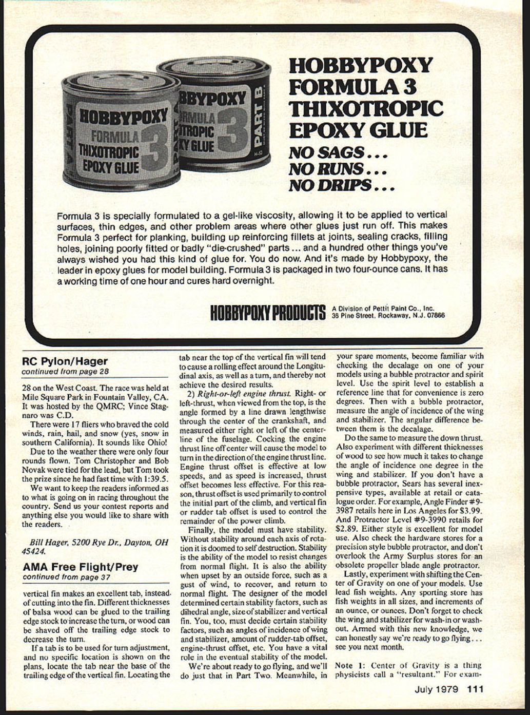
We're about ready to go flying, and we'll do just that in Part Two. Meanwhile, in your spare moments, become familiar with checking the decalage on one of your models using a bubble protractor and spirit level. Use the spirit level to establish a reference line that for convenience is zero degrees. Then with a bubble protractor, measure the angle of incidence of the wing and stabilizer. The angular difference between them is the decalage.
Do the same to measure the down thrust. Also experiment with different thicknesses of wood to see how much it takes to change the angle of incidence one degree in the wing and stabilizer. If you don't have a bubble protractor, Sears has several inexpensive types available at retail or by catalog order (examples: Angle Finder #9-3877 and Protractor Level #9-3990). Either style is excellent for model use. Also check hardware stores for a precision-style bubble protractor, and don't overlook Army Surplus stores for an obsolete propeller blade angle protractor.
Lastly, experiment with shifting the center of gravity on one of your models. Use lead fish weights—any sporting store has fish weights in all sizes and increments. Don't forget to check the wing and stabilizer for wash-in or wash-out. Armed with this new knowledge, we can honestly say we're ready to go flying... see you next month.
Note 1: Center of Gravity is a thing physicists call a "resultant."
Transcribed from original scans by AI. Minor OCR errors may remain.

