
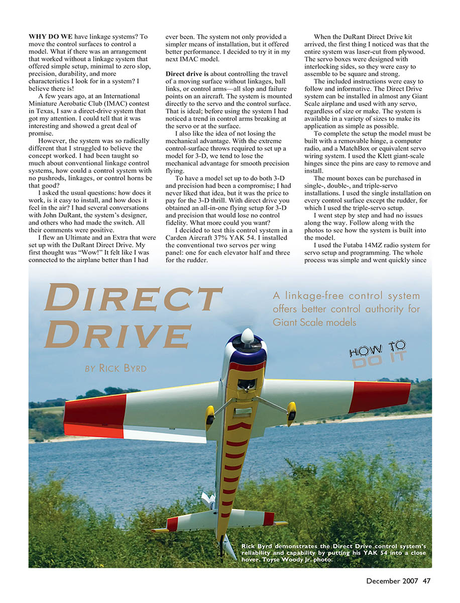
Direct Drive
By Rick Byrd
A linkage-free control system offers better control authority for Giant Scale models
Why do we have linkage systems? To move the control surfaces to control a model. What if there was an arrangement that worked without a linkage system and offered simple setup, minimal to zero slop, precision, durability, and the other characteristics I look for in a system? I believe there is!
A few years ago, at an International Miniature Aerobatic Club (IMAC) contest in Texas, I saw a direct-drive system that got my attention. I could tell that it was interesting and showed a great deal of promise. However, the system was so radically different that I struggled to believe the concept worked. I had been taught so much about conventional linkage control systems; how could a control system with no pushrods, linkages, or control horns be that good?
I asked the usual questions: how does it work, is it easy to install, and how does it feel in the air? I had several conversations with John DuRant, the system’s designer, and others who had made the switch. All their comments were positive.
I flew an Ultimate and an Extra that were set up with the DuRant Direct Drive. My first thought was “Wow!” It felt like I was connected to the airplane better than I had ever been. The system not only provided a simpler means of installation, but it offered better performance. I decided to try it in my next IMAC model.
Direct drive is about controlling the travel of a moving surface without linkages, ball links, or control arms—all slop and failure points on an aircraft. The system is mounted directly to the servo and the control surface. That is ideal; before using the system I had noticed a trend in control arms breaking at the servo or at the surface. I also like the idea of not losing the mechanical advantage. With the extreme control-surface throws required to set up a model for 3-D, we tend to lose the mechanical advantage for smooth precision flying. To have a model set up to do both 3-D and precision had been a compromise; I had never liked that idea, but it was the price to pay for the 3-D thrill. With direct drive you get an all-in-one flying setup for 3-D and precision that loses no control fidelity. What more could you want?
I decided to test this control system in a Carden Aircraft 37% YAK 54. I installed the conventional two servos per wing panel: one for each aileron half, and three for the rudder.
When the DuRant Direct Drive kit arrived, the first thing I noticed was that the entire system was laser-cut from plywood. The servo boxes were designed with interlocking sides, so they were easy to assemble square and strong.
The included instructions were easy to follow and informative. The Direct Drive system can be installed in almost any Giant Scale airplane and used with any servo, regardless of size or make. The system is available in a variety of sizes to make its application as simple as possible.
To complete the setup the model must be built with a removable hinge, a computer radio, and a MatchBox or equivalent servo wiring system. I used the Klett giant-scale hinges since the pins are easy to remove and install. The mount boxes can be purchased in single-, double-, and triple-servo installations. I used the single installation on every control surface except the rudder, for which I used the triple-servo setup. I went step by step and had no issues along the way. Follow along with the photos to see how the system is built into the model.
I used the Futaba 14MZ radio system for servo setup and programming. The whole process was simple and went quickly since there were no linkages. Each servo took half the time to install compared with a conventional linkage setup.
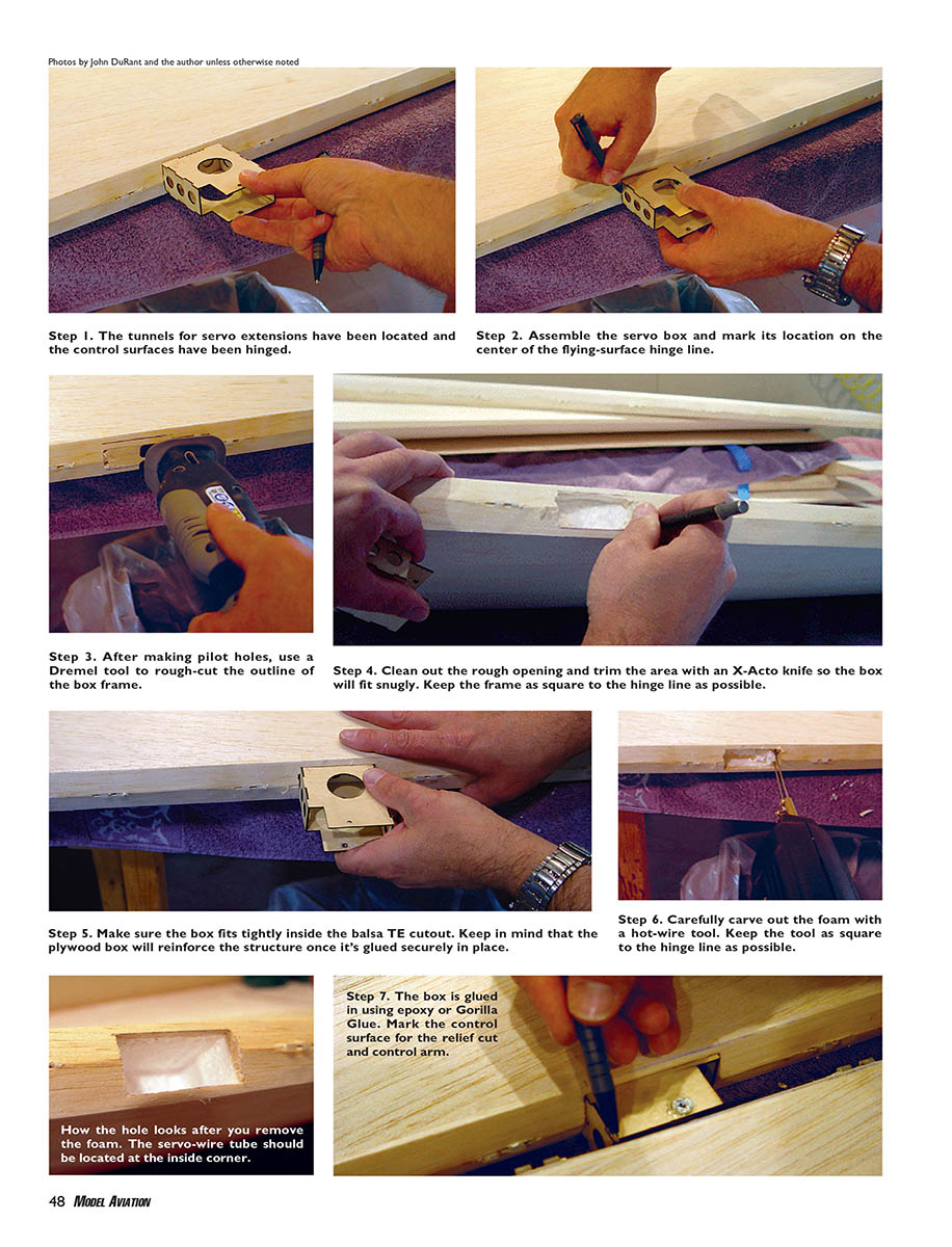
Photos by John DuRant and the author unless otherwise noted
- The tunnels for servo extensions have been located and the control surfaces have been hinged.
- Assemble the servo box and mark its location on the center of the flying-surface hinge line.
- After making pilot holes, use a Dremel tool to rough-cut the outline of the box frame.
- Clean out the rough opening and trim the area with an X-Acto knife so the box will fit snugly. Keep the frame as square to the hinge line as possible.
- Make sure the box fits tightly inside the balsa trailing-edge (TE) cutout. Keep in mind that the plywood box will reinforce the structure once it's glued securely in place.
- Carefully carve out the foam with a hot-wire tool. Keep the tool as square to the hinge line as possible.
How the hole looks after you remove the foam. The servo-wire tube should be located at the inside corner.
- The box is glued in using epoxy or Gorilla Glue. Mark the control surface for the relief cut and control arm.
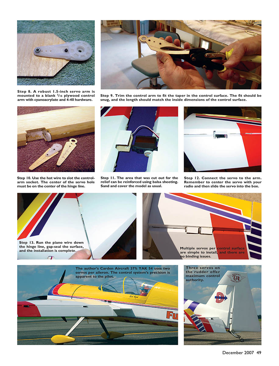
- A robust 1.5-inch servo arm is mounted to a blank 1/16" plywood control arm with cyanoacrylate and 4-40 hardware.
- Trim the control arm to fit the taper in the control surface. The fit should be snug, and the length should match the inside dimensions of the control surface.
- Use the hot wire to slot the control-arm socket. The center of the servo hole must be on the center of the hinge line.
- The area that was cut out for the relief can be reinforced using balsa sheeting. Sand and cover the model as usual.
- Connect the servo to the arm. Remember to center the servo with your radio and then slide the servo into the box.
- Run the piano wire down the hinge line, gap-seal the surface, and the installation is complete.
Multiple servos per control surface are simple to install and there are no binding issues.
The author's Carden Aircraft 37% YAK 54 uses two servos per aileron. The control system's precision is apparent to the pilot.
Three servos on the rudder offer maximum control authority.
Now for the flying part. Once I was happy with how the airplane was trimmed, I flew the 2007 IMAC Unlimited sequence. It felt great, with a more locked feel than I had ever experienced. At first I thought maybe it was me, so I asked a few local club members to fly my model. They all had the same reaction.
The most interesting thing about the field-testing was that after the guys went back to flying their airplanes they noticed a big difference between their linkage setups and the Direct Drive. The first comment I heard was that one pilot didn't realize how loose his model felt. He said he was going to switch to Direct Drive on his next airplane.
I've been flying my Carden Aircraft with the DuRant Direct Drive system for a full season. Well more than 100 flights are logged on each control surface.
I recommend this design to anyone who has a giant-scale model. The system is ideal for aerobatic models because it offers the smoothest operation and the most precise potential for control surfaces, which is the goal of any conscientious builder and aerobatic pilot.
I wasn't sure about this new state-of-the-art system at first, but now that I made the switch I'll never go back to the old linkage system. The manufacturer is more than happy to help and will answer any questions that come up. The website has great information about the setup and the history behind Direct Drive.
Rick Byrd [email protected]
Sources
- Futaba radio equipment — (800) 637-7660 — www.futaba-rc.com
- DuRant Direct Drive — (817) 243-8524 — www.durantdirectdrive.com
Transcribed from original scans by AI. Minor OCR errors may remain.

