
How To Do It: "Here—Hold This."
Ken Cashion
A workshop vise born of necessity
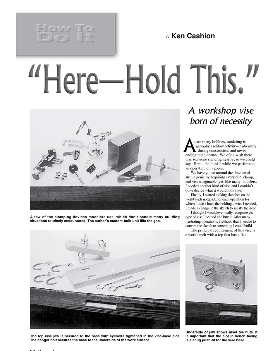
As are many hobbies, modeling is generally a solitary activity—particularly during construction and never-ending maintenance. We often wish there was someone standing nearby, so we could say "Here—hold this" while we performed an operation on a piece.
We have gotten around the absence of such a genie by acquiring every clip, clamp, and vise imaginable; yet, like many modelers, I needed another kind of vise and I couldn't quite decide what it would look like. Finally, I started making sketches on the workbench notepad. For each operation for which I didn't have the holding device I needed, I made a change in the sketch to satisfy the need. I thought I would eventually recognize the type of vise I needed and buy it. After many frustrating operations, I realized that I needed to convert the sketch to something I could build.
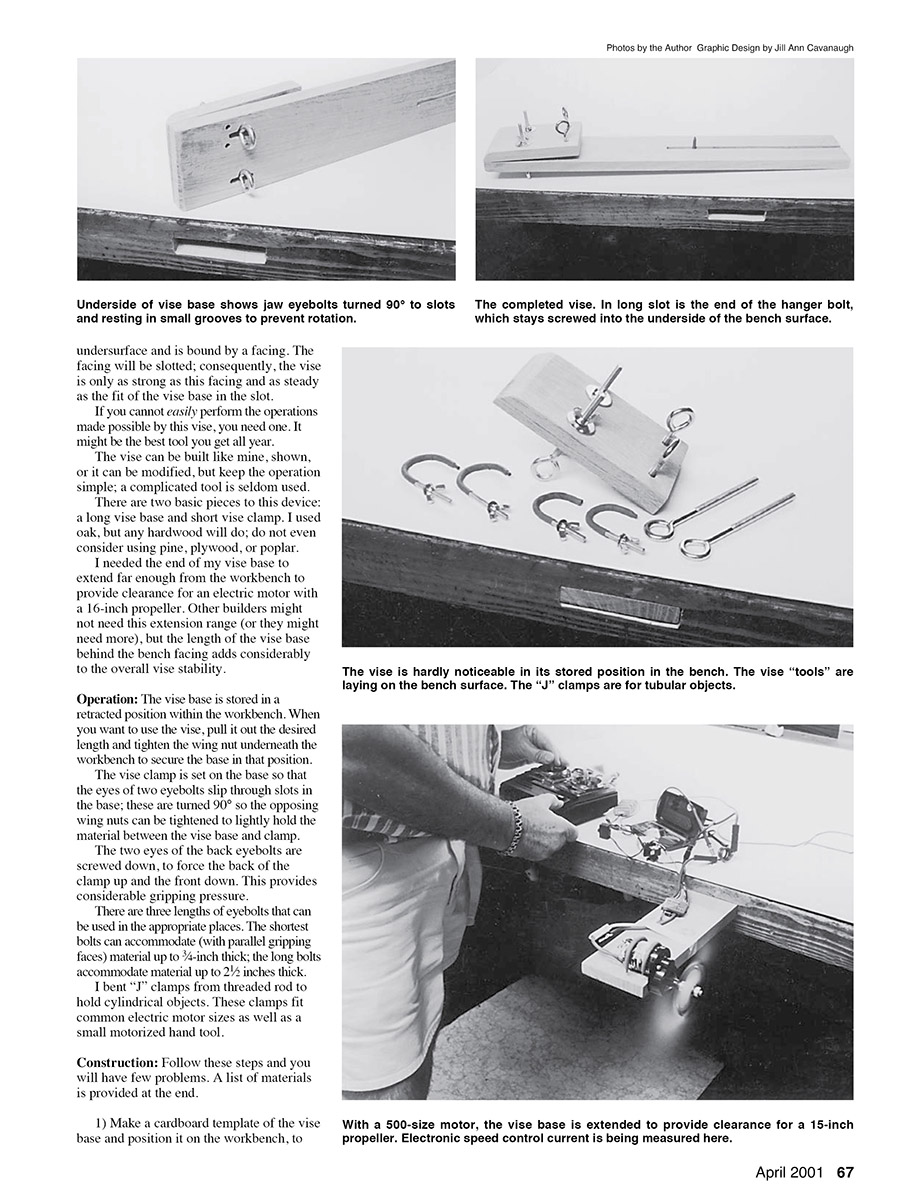
The principal requirement of this vise is a workbench with a top that has a flat undersurface and is bound by a facing. The facing will be slotted; consequently, the vise is only as strong as this facing and as steady as the fit of the vise base in the slot. If you cannot easily perform the operations made possible by this vise, you need one. It might be the best tool you get all year.
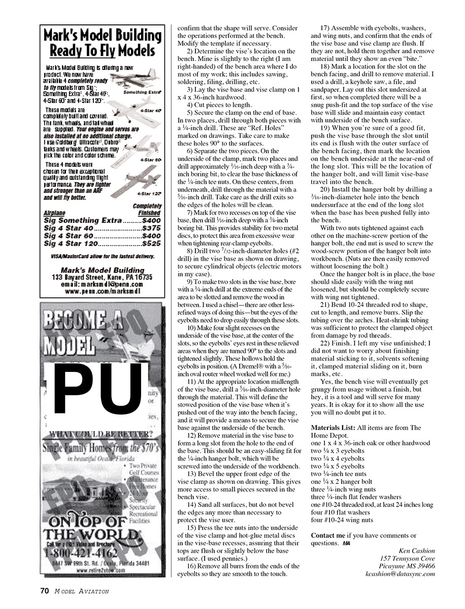
The vise can be built like mine, shown, or it can be modified, but keep the operation simple; a complicated tool is seldom used. There are two basic pieces to this device: a long vise base and a short vise clamp. I used oak, but any hardwood will do; do not even consider using pine, plywood, or poplar. I needed the end of my vise base to extend far enough from the workbench to provide clearance for an electric motor with a 16-inch propeller. Other builders might not need this extension range (or they might need more), but the length of the vise base behind the bench facing adds considerably to the overall vise stability.
Operation
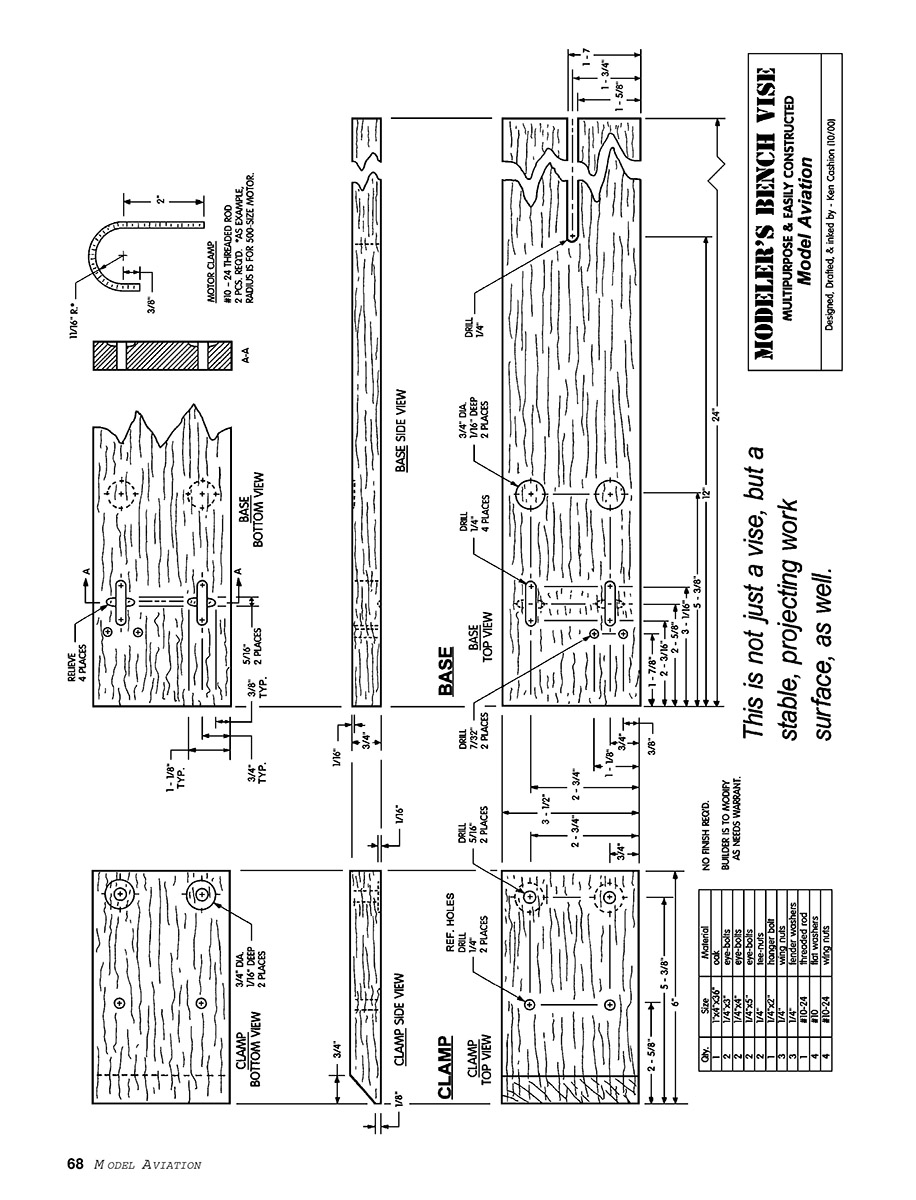
The vise base is stored in a retracted position within the workbench. When you want to use the vise, pull it out the desired length and tighten the wing nut underneath the workbench to secure the base in that position. The vise clamp is set on the base so that the eyes of two eyebolts slip through slots in the base; these are turned 90° so the opposing wing nuts can be tightened to lightly hold the material between the vise base and clamp. The two eyes of the back eyebolts are screwed down to force the back of the clamp up and the front down. This provides considerable gripping pressure.
There are three lengths of eyebolts that can be used in the appropriate places. The shortest bolts can accommodate (with parallel gripping faces) material up to 3/4-inch thick; the long bolts accommodate material up to 2 1/2 inches thick. I bent "J" clamps from threaded rod to hold cylindrical objects. These clamps fit common electric motor sizes as well as a small motorized hand tool.
Construction
Follow these steps and you will have few problems. A list of materials is provided at the end.
- Make a cardboard template of the vise base and position it on the workbench to determine the location of the long slot in the bench facing. Confirm that the shape will serve. Consider the operations performed at the bench. Modify the template if necessary.
- Determine the vise’s location on the bench. Mine is slightly to the right (I am right-handed) of the bench area where I do most of my work; this includes sawing, soldering, filing, drilling, etc.
- Lay the vise base and vise clamp on 1 x 4 x 36-inch hardwood.
- Cut pieces to length.
- Secure the clamp on the ends of the base. In two places, drill through both pieces with a 1/4-inch drill. These are "Ref. Holes" marked on drawings. Take care to make these holes 90° to the surfaces.
- Separate the two pieces. On the underside of the clamp, mark two places and drill approximately 1/16-inch deep with a 3/4-inch boring bit to clear the base thickness for the 1/4-inch tee nuts. On these centers, from underneath, drill through the material with a 5/16-inch drill. Take care as the drill exits so the edges of the holes will be clean.
- Mark for two recesses on top of the vise base, then drill 1/16-inch deep with a 3/4-inch boring bit. This provides stability for two metal discs, to protect this area from excessive wear when tightening rear-clamp eyebolts.
- Drill two 7/32-inch-diameter holes (#2 drill) in the vise base as shown on drawing, to secure cylindrical objects (electric motors in my case).
- To make two slots in the vise base, bore with a 1/4-inch drill at the extreme ends of the area to be slotted and remove the wood in between. I used a chisel—there are other less-refined ways of doing this—but the eyes of the eyebolts need to drop easily through these slots.
- Make four slight recesses on the underside of the vise base, at the center of the slots, so the eyebolts' eyes rest in these relieved areas when they are turned 90° to the slots and tightened slightly. These hollows hold the eyebolts in position. (A Dremel® with a 5/16-inch oval router wheel worked well for me.)
- At the appropriate location midlength of the vise base, drill a 5/16-inch-diameter hole through the material. This will define the stowed position of the vise base when it's pushed out of the way into the bench facing, and it will provide a means to secure the vise base against the underside of the bench.
- Remove material in the vise base to form a long slot from the hole to the end of the base. This should be an easy sliding fit for the 1/4-inch hanger bolt, which will be screwed into the underside of the workbench.
- Bevel the upper front edge of the vise clamp as shown on drawing. This gives more access to small pieces secured in the bench vise.
- Sand all surfaces, but do not bevel the edges any more than necessary to protect the vise user.
- Press the tee nuts into the underside of the vise clamp and hot-glue metal discs in the vise-base recesses, assuring that their tops are flush or slightly below the base surface. (I used pennies.)
- Remove all burrs from the ends of the eyebolts so they are smooth to the touch.
- Assemble with eyebolts, washers, and wing nuts, and confirm that the ends of the vise base and vise clamp are flush. If they are not, hold them together and remove material until they show an even "bite."
- Mark a location for the slot on the bench facing, and drill to remove material. I used a drill, a keyhole saw, a file, and sandpaper. Lay out this slot undersized at first, so when completed there will be a snug push-fit and the top surface of the vise will slide and maintain easy contact with underside of the bench surface.
- When you're sure of a good fit, push the vise base through the slot until its end is flush with the outer surface of the bench facing, then mark the location on the bench underside at the near end of the long slot. This will be the location of the hanger bolt, and will limit vise-base travel into the bench.
- Install the hanger bolt by drilling a 5/16-inch-diameter hole into the bench undersurface at the end of the long slot when the base has been pushed fully into the bench. With two nuts tightened against each other on the machine-screw portion of the hanger bolt, the end nut is used to screw the wood-screw portion of the hanger bolt into the workbench. (Nuts are then easily removed without loosening the bolt.) Once the hanger bolt is in place, the base should slide easily with the wing nut loosened, but should be completely secure with the wing nut tightened.
- Bend 10-24 threaded rod to shape, cut to length, and remove burrs. Slip heat-shrink tubing over the arches to protect the clamped object from damage by the rod threads.
- Finish. I left my vise unfinished; I did not want to worry about finishing material sticking to it, solvents softening it, clamped material sliding on it, burn marks, etc. Yes, the bench vise will eventually get grungy from usage without a finish, but it is a tool and will serve for many years. It is okay for it to show all the use you will no doubt put it to.
Materials List
- one 1 x 4 x 36-inch oak or other hardwood
- two 1/4 x 3-inch eyebolts
- two 1/4 x 4-inch eyebolts
- two 1/4 x 5-inch eyebolts
- two 1/4-inch tee nuts
- one 1/4 x 2-inch hanger bolt
- three 1/4-inch wing nuts
- three 1/4-inch flat fender washers
- one 10-24 threaded rod, at least 24 inches long
- four #10 flat washers
- four #10-24 wing nuts
Contact me if you have comments or questions.
Ken Cashion 157 Tennyson Cove Picayune, MS 39466 [email protected]
Transcribed from original scans by AI. Minor OCR errors may remain.

