
How To Do It: Laser Cut Your Own Parts
TURN YOUR PLANS INTO A KIT
by Fred Randall
I was bitten by the model airplane bug early. I started designing models in the early 1940s while the planet was ablaze with World War II. Although not rationed, balsa wood, like many other items, was impossible to get. So when my Uncle Bob returned on leave from the Merchant Marines with a duffle bag filled with large blocks of the stuff, I was ecstatic!
He explained to me that the life rafts aboard ship were simple, solid balsa structures covered with canvas, and one broke apart when some unsecured equipment slid into it. Knowing I was an avid modeler, he rescued some of the balsa and brought it home for me. To this day, I don’t know whether his gift was “authorized” or not!
The Liberty ship on which he served regularly braved the U-boat wolf packs of the North Atlantic, ferrying war materials to the embattled British. During one such expedition, my uncle lost his life.
An older man who lived near my childhood home had a woodworking shop in his garage. He cut my blocks into 1/8-inch thick planks for me. For the next couple of years all of my model-building materials were cut from those planks.
As an 8-year-old, model airplane design was an activity that took place on our enameled metal kitchen table using #2 school pencils, a yardstick, and a roll of shelf paper. My passion was rubber-powered free-flight models, and the fact that rubber for the motors was unavailable didn’t deter me.
My mother made no secret of the fact that she wished I would put as much effort into my schoolwork as I did enlarging wing ribs from Air Trails plans using homemade graph paper, and cutting them out with a single-edge razor blade. I drifted out of the hobby several years later, when I discovered girls!
At the time, model airplane kits came with balsa “printwood” that needed to be carefully cut out by hand. The models were covered with Japanese tissue, silkspan, or in some cases, silk. Heat-shrink film had not yet been invented. The laser was a laboratory curiosity and ARFs didn’t exist. Precut kits and premade models were a dream for the future.
But times have changed. When I returned to the aircraft modeling hobby six years ago, the dream had come to fruition! I reduced several ARF trainers to splinters and balsa dust while exploring the mysteries of RC. I still experience shaky knees and sweaty palms when my airplanes are aloft!
When my models began to survive longer than a few weeks I decided to start designing my own as I had done so many years ago. The design process had changed drastically, as well.
I had worked in a technical trade before retirement and was reasonably computer-literate. After making several sketches of my proposed airplane, I looked for a CAD program that would make the design work easier and more enjoyable.
I was familiar with AutoCAD, but I couldn't justify the cost of such a program for designing model airplanes. A Google search unearthed a program called ModelCAD 3000 from Upperspace Software. The price was reasonable, so I ordered it along with a companion program: Wingmaster.
It took me some time to get the hang of using the programs but it was well worth it. The programs were downloadable and there was a 275-page PDF user's manual. I occasionally referred to it, but my main sources of instructions were the program help files.
My pencil sketches were of a 1930s-style racer, one of my favorite types of aircraft. I am a product of that generation, so perhaps my preference is natural.
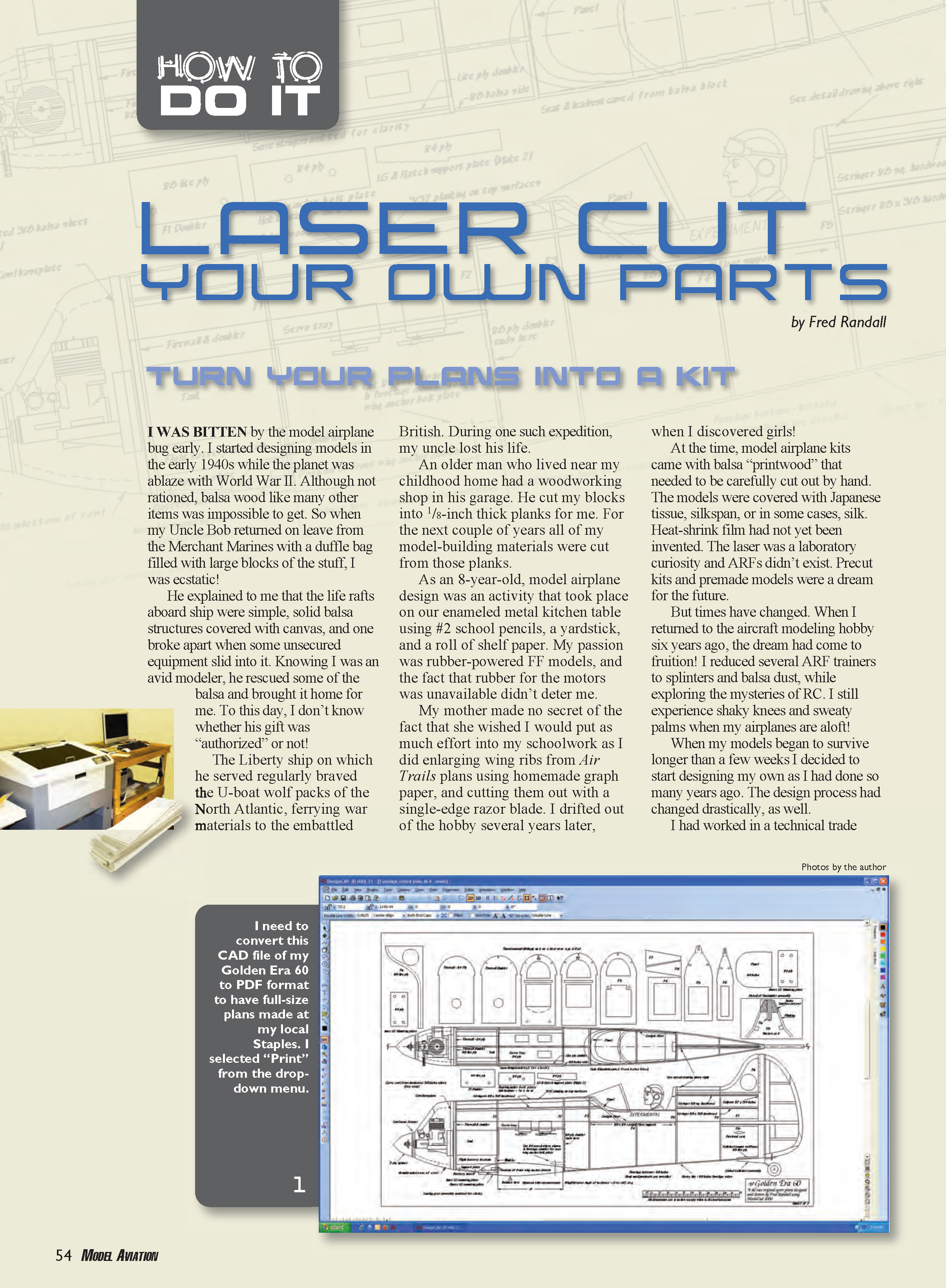
Slowly, I transferred my rough sketches to computer files. I didn't like the looks of constant chord wings, but the thought of having to scroll-saw-cut a group of different size ribs led me to a design that utilized contoured balsa ailerons to provide a more pleasing outline to an otherwise rectangular wing planform (my CAD-designed plan became the Golden Era 60).
I had seen laser-cut parts used on ARFs and wished that I could find a way to have my parts cut for me. I delight in assembling a model aircraft, but fabricating a multitude of balsa and plywood parts is not as enjoyable.
It was by chance that I mentioned this wish to Joe Candela, the proprietor of Creative Hobbies. Joe had answered my many questions about RC flying during a dozen or so visits to his establishment—before I had bought anything at all! I had approached people in several other hobby shops with my questions, but most were reluctant to take time for me unless I was a paying customer, so when it came time to finally buy airplanes and equipment, Joe got my business.
Joe responded to my casual comment by saying, "Bring in your patterns; we've got a 100-watt Epilog Radius laser engraver out back."
I was stunned! I immediately began learning how this unfamiliar device worked. A laser cutter or engraver is simply a computer printer that etches or cuts material using information downloaded from the computer, rather than printing it out on paper.
Creative Hobbies is a multifaceted business, and the laser device had been used to etch glass plates and plaques used in another type of hobby. It had never been used for the production of airplane parts, and Joe was as interested as I to explore the possibility.
The cutter was used mainly with CorelDRAW files, and it didn't understand my ModelCAD drawings. Therefore I installed ModelCAD in the computer that controlled the cutter, and obtained a new keycode from Upperspace. This allowed the parts layouts to be cut from within the ModelCAD 3000 environment.
We found that the cutter would make precise scale parts from the installed ModelCAD prints. It was a matter of making the print scale 1:1, arranging the rib or former patterns to fill the sheet of material to be cut, and selecting the Epilog laser cutter as the printer of choice.
After arranging the images of formers and ribs to make the best use of the 24 x 12-inch sheets of 1/8- and 1/4-inch plywood, we loaded a sheet of 1/8-inch light plywood onto the laser bed. The speed and power of the cutter was adjusted for the thickness of the wood and a 1:1 scale "print" was ordered.
The laser head began to move, seemingly without any logical pattern, making a small cut here, moving across the plywood, and making another. The resultant smoke was exhausted outside with a powerful blower. The process continued until a perfect reproduction of the CAD pattern had been transferred to the wood.
It didn't look as if it had cut all the way through, but when the protective hood was lifted and we picked up the plywood, all of the parts fell away, perfectly cut to size. The total time for one 24 x 12-inch sheet was 8 minutes. Only 8 minutes for more than a dozen accurate parts!
We used the same process to cut the remaining 1/8-inch and 1/4-inch plywood pieces and the 3/8 x 3 x 24-inch balsa sheet for the tail feathers. The balsa pieces were considerably charred, so we placed a second sheet of dampened balsa in the machine and reduced the power by roughly 25%. This time the balsa parts came out fine. The entire job was completed in approximately 1 1/2 hours; the total machine time was 39 minutes.
Getting Your Parts Cut:
Because I installed the ModelCAD program in the control computer, I could use the program files for cutting; however there is a more mainstream way to do it.
ModelCAD, as do all CAD programs of which I am aware, generates vector graphic files. The difference between raster and vector graphics was well covered in "Designing in CAD," David Walker's excellent introduction to CAD in the August 2011 issue of MA.
Before you become unhinged at the thought of having to purchase a pricey program such as AutoCAD or CorelDRAW in order to produce your laser-cut patterns, there are alternatives. The key is that the program must be capable of exporting .dxf or .dwg files.
Although ModelCAD 3000 is still available, its exported .dxf conversions leave much to be desired. Because of this, and because of its increased capability, I have switched to DesignCAD v21. This program functions like ModelCAD and doesn't require learning new procedures; however, it allows direct import and export of AutoCAD-readable .dwg and .dxf drawings. I can also import and update my earlier ModelCAD drawings. I recommend DesignCAD because it is easier to learn than most other CAD programs.
DesignCAD is available from IMSI Design. The 2-D version is less than $50, and is all you need to develop good laser-cutter-useable drawings. If you prefer to use an AutoCAD-type program there are "clones" available at bargain prices, many with free trials. The price and availability of the software listed at the end of the article was accurate at the time of this writing, but subject to change.
Some programs and options to consider:
- TurboCAD: used by many model designers; can be found for as little as $40 for the 2-D (Designer) version.
- IntelliCAD: an AutoCAD clone; approximately $111 (free trial available).
- QCAD: about $36 (offers a free trial).
- CorelDRAW Suite 12 (older version): available on eBay for around $50; includes more than 100 import/export filters plus scalable vector graphics (SVG).
It is my understanding that all of these programs export the necessary .dxf drawings. If you are a skillful Internet surfer, other alternatives may be found that also export files in this format.
You do not need a program capable of 3-D rendering. Usually, programs with that capability cost more, and the learning curve is steeper. The simpler programs are easier to use than the more complex ones, which was why I gravitated to ModelCAD. Perhaps it was a mistake because it created non-.dxf vector graphic files. I was fortunate to have access to a laser cutter that I could experiment with and develop a workaround solution to getting my parts cut.
You might ask, "Why can't I submit my paper drawings to a laser-cutting company?"
I exchanged several emails with Charlie of Manzano Laser Works. Charlie was an absolute oracle in filling some of the gaps in my knowledge of the ways of the commercial laser cutter, and I thank him for his time and good counsel.
This is a direct quote from one of his emails: "Conversion of paper plans to cut files is a huge problem these days. We turn down several jobs a week from folks who have plans they want parts cut from (we turn them down because of a lack of time)."
It is a difficult and time-consuming process to convert paper plans to a format understood by a laser cutter. For this reason, even if you can find someone willing to do the conversion, the cost is high. If you are interested in designing your own airplanes, it is worth the effort and expense to learn to use a CAD program that exports .dxf files. The benefits, beyond those already mentioned, include having full-size plans made at most office supply stores and easily exchanging plans and ideas with other modelers.
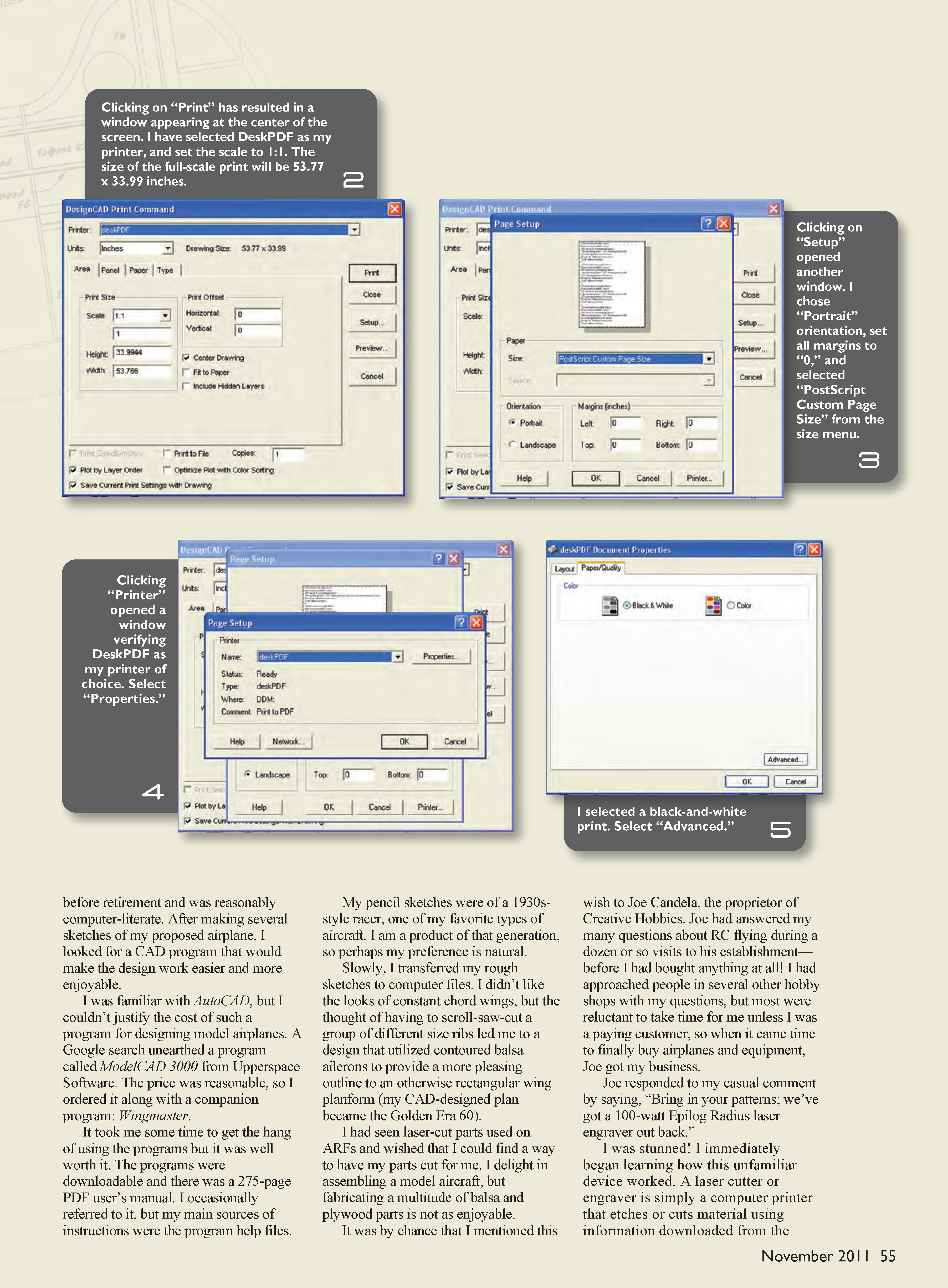
There is another possibility to explore. Most large-scale commercial printers use PDF files. In most cases, your drawings can be converted to PDF format using an inexpensive program called DeskPDF Professional from a company called Docudesk. Other conversion utilities that perform the same operation may be available.
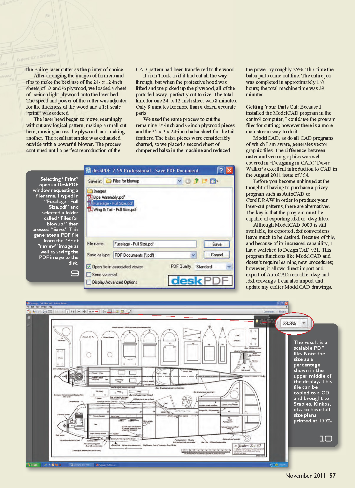
DeskPDF installs on your computer as a virtual printer driver. When you choose to "print" a file or drawing, DeskPDF shows up in the printer box as an available printer. I use DeskPDF-converted files to submit my plans to MA for reproduction and sale. DeskPDF creates a scalable duplicate of your drawing in PDF format. Just select 1:1 as the scale size instead of using the fit-to-paper option.
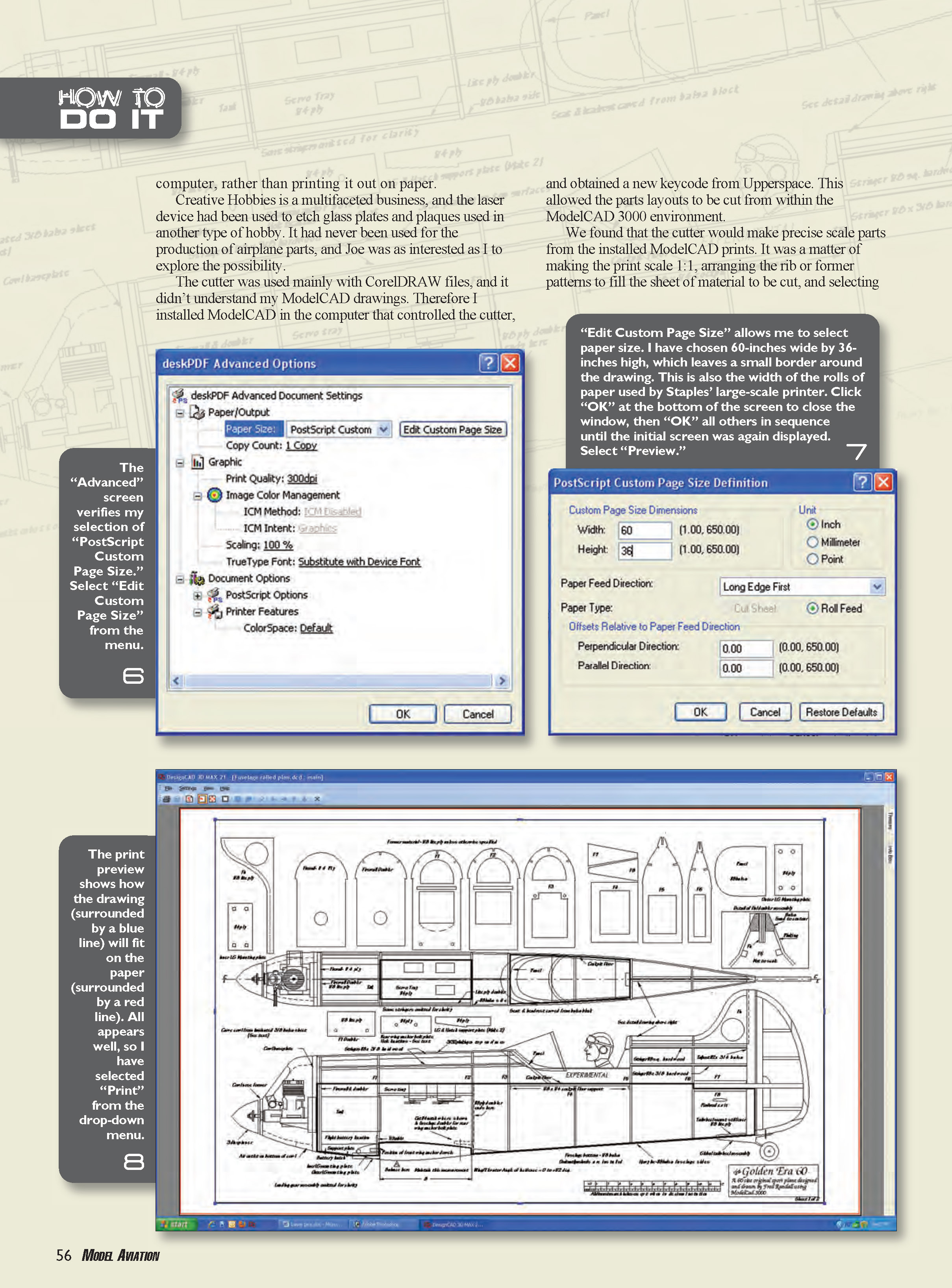
The PDF file can be taken to any office supply store that has a large-format printer. You can print full-size plans of your drawing. The cost is based on the number of square inches the plans occupy and usually runs between $5 and $20. If you intend to submit CAD-drawn plans to MA for publication, PDF is the way to go.
Most of us do not have access to a wide-format plotter, and being able to use a readily available printing service is a huge advantage. It's necessary to limit the height of your full-size drawings to 36 inches, but because the printer uses roll paper, length can be anything practical.
In order to get your parts cut, you must design "cutting patterns." You need to know the size of the laser bed and the size of available materials from which to cut your parts. You must then provide cutting patterns that best utilize the size of material that you plan to use.
There are two schools of thought concerning cutting patterns. Most commercial firms like to leave small "lands" that prevent the cut parts from falling out of the material from which they are cut. It makes it easier for the cutter to provide illustrations of the parts for identification while still attached. Packaging is also easier because the parts are on flat boards rather than in bundles; however, it does require the builder to cut each component free at the time of use.
I like my parts completely cut out and bundled with rubber bands—wing parts in one bundle, fuselage parts in another, etc. This also minimizes the amount of sanding you have to do to prepare the cut parts for installation, because the attachment "nubs" don't need to be sanded off.
In either case, the part number of each component should be etched into it at the time the part is cut. This is usually facilitated by having the part number in a different color, or on a different "layer" of the CAD cutting pattern.
The Cost:
Usually the cost of laser cutting is determined by the actual amount of run time that it takes for the machine to cut your parts (approximately $1 per minute), the time that it takes for the operator to do the entire job, the set-up charge, the cost of materials, and the shipping cost. A 60-size airplane will run in the neighborhood of $85 to $100. Smaller models will cost less, as will batch jobs (several identical sets of parts), in which the cost per set can usually be negotiated.
In any event, you must negotiate with the service you intend to use. Don't simply send your prints or files and expect the lowest possible price. The more you do to prepare your patterns for their cutting environment, the less that the service will have to do, lowering the overall cost.
I hope I've cleared up some of the mysteries surrounding the production of laser-cut parts.
Keep building, and keep 'em flying! MA
Sources:
- Fred Randall
- [email protected]
- Manzano Laser Works
- [email protected]
- http://manzanolaser.com
- Creative Hobbies
- (508) 473-8259
- www.creativehobbies.net
- IMSI Design
- (415) 483-8000
- http://imsidesign.com
- IntelliCAD
- (503) 293-7655
- www.intellicad.org
- QCAD
- www.qcad.org
- Docudesk
- (972) 359-0655
- www.docudesk.com
Transcribed from original scans by AI. Minor OCR errors may remain.

