
Matchmaking
By A.G. "Andy" Lennon
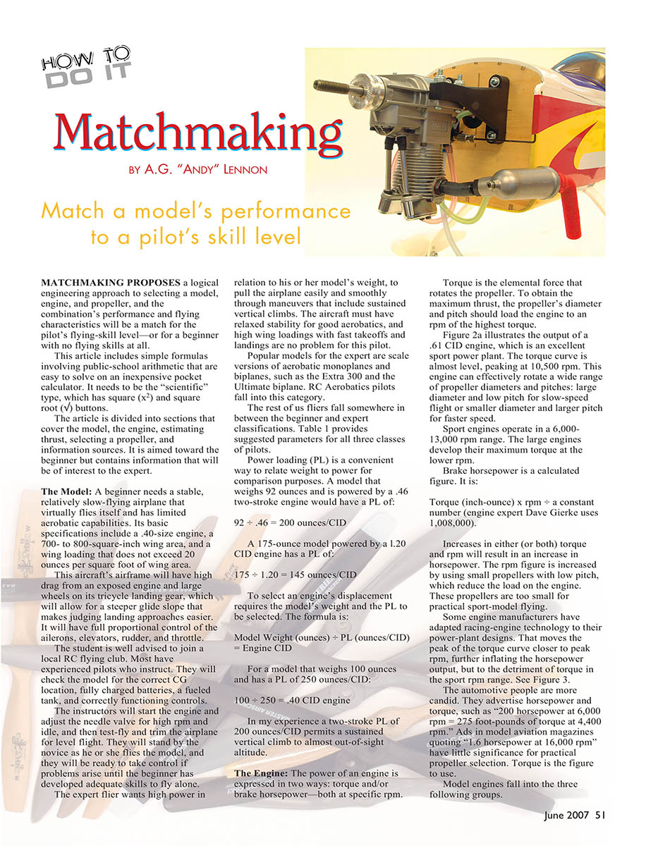
MATCHMAKING proposes a logical engineering approach to selecting a model, engine, and propeller so the combination's performance and flying characteristics match the pilot's skill level—or a beginner with no flying skills at all.
This article includes simple formulas involving public-school arithmetic that are easy to solve on an inexpensive pocket calculator. It needs to be the "scientific" type, which has square (x²) and square-root (√) buttons. The article is divided into sections that cover the model, the engine, estimating thrust, selecting a propeller, and information sources. It is aimed toward the beginner but contains information that will be of interest to the expert.
The Model
A beginner needs a stable, relatively slow-flying airplane that virtually flies itself and has limited aerobatic capabilities. Basic specifications for a trainer include approximately a .40-size engine, a 700–800 square-inch wing area, and a wing loading that does not exceed 20 ounces per square foot of wing area. This aircraft's airframe will have relatively high drag from an exposed engine and large wheels on its tricycle landing gear, which allows a steeper glide slope and makes judging landing approaches easier. It should have full proportional control of ailerons, elevator, rudder, and throttle.
New students are well advised to join a local RC flying club. Most clubs have experienced pilots who instruct. They will check the model for correct CG location, fully charged batteries, a fueled tank, and correctly functioning controls. Instructors will start the engine, adjust the needle valve for high rpm and idle, test-fly and trim the airplane for level flight, and stand by the novice as he or she flies the model—ready to take control if problems arise until the beginner develops adequate skills to fly alone.
The expert flier wants high power in relation to the model's weight to pull the airplane easily and smoothly through maneuvers including sustained vertical climbs. The aircraft must have relaxed stability for good aerobatics; high wing loadings with fast takeoffs and landings are no problem for this pilot. Popular expert models include scale versions of aerobatic monoplanes and biplanes such as the Extra 300 and the Ultimate biplane. RC aerobatics pilots fall into this category.
Most pilots fall between beginner and expert. Table 1 provides suggested parameters for the three classes.
Table 1 — Suggested parameters by pilot class:
- Expert
- Speed: 100–125 mph
- Wing loading: 25–35 oz/ft²
- Power loading (PL): Two-stroke 100–200 oz/CID; Four-stroke 90–180 oz/CID
- Intermediate
- Speed: 80–100 mph
- Wing loading: 20–25 oz/ft²
- PL: Two-stroke 200–250 oz/CID; Four-stroke 180–225 oz/CID
- Beginner
- Speed: 60–80 mph
- Wing loading: 15–20 oz/ft²
- PL: Two-stroke 250–300 oz/CID; Four-stroke 225–270 oz/CID
Power loading (PL) relates model weight to engine displacement for comparison purposes:
- Example: A model that weighs 92 ounces and is powered by a .46 CID two-stroke has a PL of:
- 92 ÷ 0.46 = 200 ounces/CID
- Example: A 175-ounce model powered by a 1.20 CID engine has a PL of:
- 175 ÷ 1.20 = 145 ounces/CID
To select engine displacement given model weight and desired PL:
- Model Weight (ounces) ÷ PL (ounces/CID) = Engine CID
- Example: For a 100-ounce model with a PL of 250 ounces/CID:
- 100 ÷ 250 = 0.40 CID engine
In my experience a two-stroke PL of 200 ounces/CID permits a sustained vertical climb to almost out-of-sight altitude.
The Engine
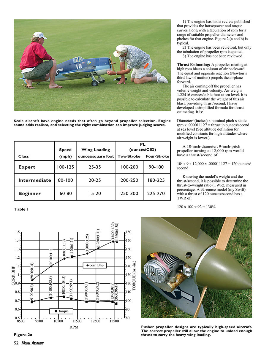
Engine power is expressed as torque and/or brake horsepower—both at specific rpm. Torque is the elemental force that rotates the propeller. To obtain maximum thrust, the propeller's diameter and pitch should load the engine to an rpm near the highest torque. (Figure 2a in the original article illustrates a typical .61 CID engine whose torque curve is almost level, peaking near 10,500 rpm.) Such an engine can effectively rotate a wide range of propeller diameters and pitches: large diameter and low pitch for slow-speed flight, or smaller diameter and larger pitch for faster speed.
Sport model engines typically operate in a 6,000–13,000 rpm range. Larger engines usually develop maximum torque at the lower end of that range.
Brake horsepower may be calculated from torque and rpm:
- Brake HP = Torque (inch-ounces) × rpm ÷ 1,000,000 (constant used by engine expert Dave Gierke)
Increases in torque, rpm, or both result in increased horsepower. Increasing rpm is achieved by using small, low-pitch props that reduce engine load; however, these props are usually too small for practical sport-model flying.
Some manufacturers have adapted racing-engine technology, moving the peak of the torque curve closer to peak rpm. This inflates peak horsepower figures but can reduce usable torque in the sport rpm range. For practical propeller selection, torque is the figure to use.
Three groups of model engine information availability:
- The engine has a published review that provides horsepower and torque curves plus a tabulation of rpm for a range of propeller diameters and pitches (ideal).
- The engine has a review but only a tabulation of propeller rpm is quoted.
- The engine has not been reviewed.
Thrust Estimating
A propeller rotating at high rpm accelerates a column of air backward; the equal and opposite reaction propels the airplane forward. Air at sea level weighs about 1.22416 ounces per cubic foot. The following simplified formula estimates thrust (ounces/second) at sea level:
- Thrust (oz/sec) = Diameter² (inches) × Nominal Pitch (inches) × Static rpm × 0.000011127
(Note: the constant 0.000011127 applies at sea level; use a modified constant for high altitudes where air density is lower.)
Example:
- A 10-inch diameter, 9-inch pitch prop at 12,000 rpm:
- 10² × 9 × 12,000 × 0.000011127 = 120 oz/sec
Thrust-to-weight ratio (TWR), expressed as a percentage, is:
- TWR (%) = Thrust (oz/sec) × 100 ÷ Model Weight (oz)
Example:
- A 92-ounce model with 120 oz/sec thrust:
- TWR = 120 × 100 ÷ 92 = 130%
Empirically, TWR is proportional to the angle of climb the model can sustain indefinitely. TWR percentages are a more accurate appraisal than PL because engines with the same CID from different manufacturers are not equally powerful.
If you have an engine and want to estimate suitable model weight from a known thrust:
- Model Weight (oz) = Thrust (oz/sec) × 100 ÷ TWR(%)
- Example with thrust = 134 oz/sec:
- For TWR 125%: Model Weight ≈ 134 × 100 ÷ 125 = 107 oz
- For TWR 100%: Model Weight = 134 oz
- For TWR 75%: Model Weight ≈ 178 oz
- For TWR 50%: Model Weight ≈ 268 oz
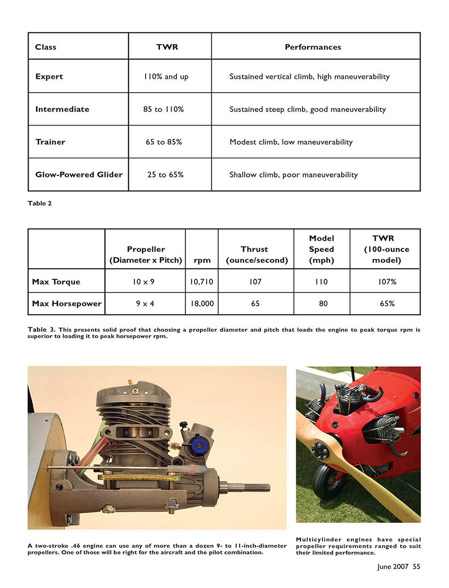
Table 2 — TWR vs. typical performance:
- Expert: TWR 110% and up — sustained vertical climb, high maneuverability
- Intermediate: TWR 85–110% — sustained steep climb, good maneuverability
- Trainer: TWR 65–85% — modest climb, low maneuverability
- Glow-powered glider: TWR 25–65% — shallow climb, poor maneuverability
Propeller Selection
Objective: Select a propeller diameter and pitch that load the engine to, or close to, its peak torque rpm and that propel the model, in level flight, at the selected speed. The procedure differs depending on which engine-information group applies.
Group 1) Brake horsepower, torque curves, and rpm table available
- Refer to the engine's torque curve and rpm table.
- Identify peak torque rpm. Select a prop whose rpm in the table matches the peak torque rpm.
- If the resulting prop gives a speed different from your desired level-flight speed, reduce/increase pitch accordingly while maintaining the same load (rpm).
Use Dave Gierke's Propeller Load Factor (PLF):
- PLF = Diameter² × Pitch
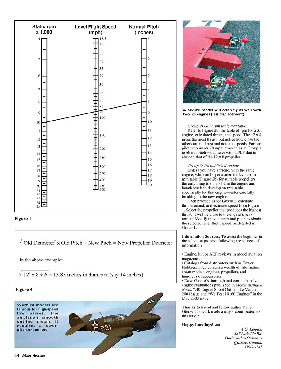
To find a new diameter for a different pitch while keeping approximately the same load:
- New Diameter = sqrt(Old Diameter² × Old Pitch ÷ New Pitch)
Example:
- Original prop: 12 × 8 at 10,500 rpm (peak torque) gives 95 mph.
- Desired speed: 70 mph. At 10,500 rpm, 6-inch pitch gives ~70 mph.
- Find diameter for 6-inch pitch with same load:
- New Diameter = sqrt(12² × 8 ÷ 6) = sqrt(144 × 8 ÷ 6) = sqrt(192) = 13.85 → choose 14 inches
- The 14 × 6 PLF (14² × 6 = 1,176) is close to the 12 × 8 PLF (1,152) and will load the engine similarly.
If a higher speed is required, use the same rpm (peak torque rpm) and select a higher pitch to obtain that speed; then compute diameter with the PLF formula.
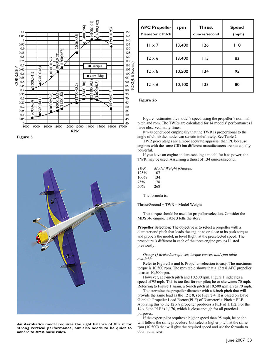
Group 2) Only rpm table available
- Use the rpm table to find props that give rpm near peak torque (or that produce the most thrust).
- Compare thrust and speeds from the table. For a desired speed, proceed as in Group 1: choose pitch for the target speed and compute diameter so PLF is close to the best-performing prop in the table.
Group 3) No published review
- If no review or rpm table exists, bench-test the engine after carefully breaking it in to develop an rpm table for candidate propellers.
- Calculate thrust/second and estimate speed from nominal pitch and rpm.
- Select the prop that produces the highest thrust (it will be near peak torque). Modify diameter and pitch to achieve the desired level-flight speed using the PLF equation described above.
Table 3 — Example showing torque vs. horsepower loading (same engine, two different props):
- Prop: 10 × 9 (loaded to peak torque)
- rpm: 10,710
- Thrust: 107 oz/sec
- Model speed: 110 mph
- TWR (for a 100-oz model): 107%
- Prop: 9 × 4 (loaded to peak horsepower)
- rpm: 18,000
- Thrust: 65 oz/sec
- Model speed: 80 mph
- TWR (for a 100-oz model): 65%
This demonstrates that choosing a prop that loads the engine to peak torque rpm generally produces superior thrust and climb capability compared with loading the engine to peak horsepower rpm.
Information Sources
- Engine, kit, or ARF reviews in model aviation magazines.
- Catalogs from distributors such as Tower Hobbies, which contain information about models, engines, propellers, and accessories.
- Dave Gierke's thorough engine evaluations in Model Airplane News: "40 Engine Shoot Out" (March 2001) and "We Test 10 .60 Engines" (May 2003).
Thanks to friend and fellow author Dave Gierke; his work made a major contribution to this article.
Happy landings! MA
A.G. Lennon 487 Oakville Rd. Dollard-des-Ormeaux Quebec, Canada H9G 1M1
Transcribed from original scans by AI. Minor OCR errors may remain.

