
Mounting Large Outrunner Motors
by Curtis Mattikow
With the inexpensive and powerful outrunner motors and Li-Poly batteries available nowadays, a new wave of larger models is being converted from glow to electric operation. Many of these bigger aircraft come with beam mounts that are unsuitable for motors, and motors are usually considerably shorter than their glow-engine equivalents, so the motors can seldom be bolted directly to the firewall.
A few large motor mounts are available commercially, but they are sometimes expensive and hard to get. The following photo-illustrated method shows simple steps required to mount motors. The only things necessary are a few dollars' worth of plywood (often available in your scrap box) and about an hour of time.
What You Need:
- A table saw with a fence (hand sawing accurately is difficult and time-consuming).
- A ruler and pencil.
- Five-minute epoxy.
- Screws for mounting the motor.
- Appropriate plywood (I used 1/4-inch aircraft-grade plywood from Midwest Products).
- Optionally: drill and bits, clamps, thin cyanoacrylate (CA) for hardening screw holes.
- Motor example: a Tower Pro outrunner equivalent to a .50-size glow engine.
- Note: You could use 3/16-inch plywood for smaller motors, but 1/4-inch will be adequate even for large motors (up to 90 class). Lightening holes can save weight without sacrificing rigidity.
Mounting Tips:
- Check how your propeller driver, spinner, and propeller assemble; some electric propellers and spinners extend rearward behind the prop driver, so account for that when measuring.
- Firmly clamp the assembly while the epoxy cures — clamping pressure greatly improves epoxy joint strength.
- As a roughening aid, drill a few 1/16-inch holes in the gluing areas to give the epoxy more bite.
- This is a quick, inexpensive technique that produces a very strong, rigid mount. I made both mounts for the Nitro Model Planes B-25 Mitchell in less than an hour.
- The great thing about electric motors is there is no needle valve or exhaust muffler to carve out of the cowling. Ensure there are openings for cooling air to pass.
Give it a whirl!
MA
Curtis Mattikow [email protected]
Step-by-step Mounting Procedure
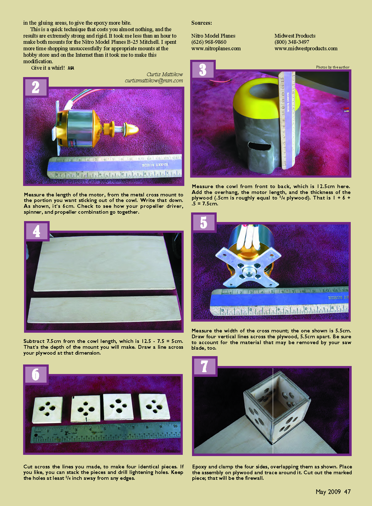
- Measure the length of the motor from the metal cross mount to the portion you want sticking out of the cowl. Write that down (example: 6 cm). Check how your propeller driver, spinner, and propeller fit together and add any rearward extensions to your measurement.
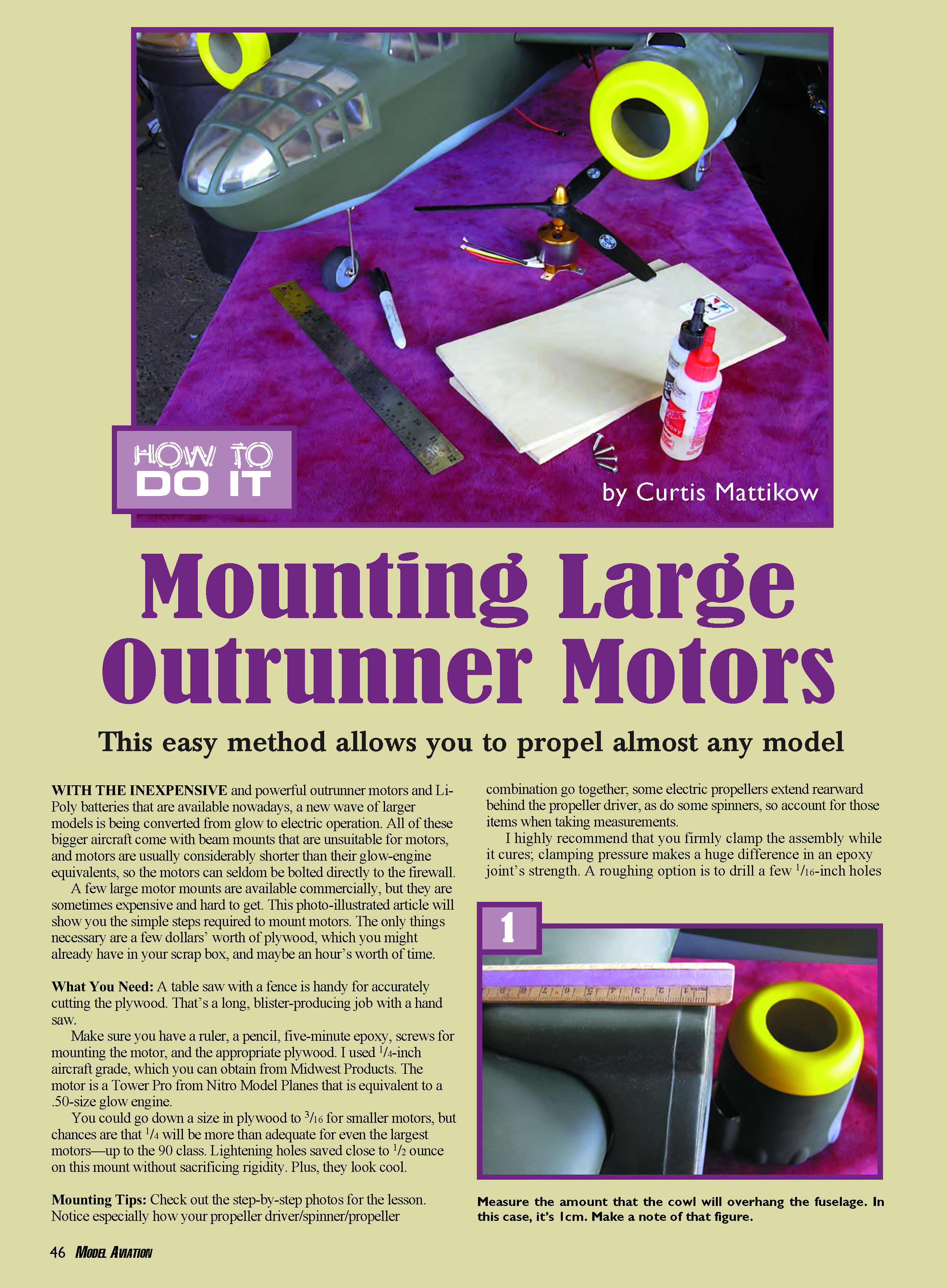
- Measure the inside length of the cowl from front to back (example: 12.5 cm).
- Determine the overhang (example: 1 cm) and the plywood thickness (example: 0.5 cm for 1/4-inch plywood in these measurements). Add the overhang, motor length, and plywood thickness: 1 + 6 + 0.5 = 7.5 cm.
- Subtract that total from the cowl length to get the required mount depth: 12.5 - 7.5 = 5 cm. Draw a line across your plywood at that dimension to mark the depth.
- Measure the width of the motor cross mount (example: 5.5 cm). On the plywood, draw four vertical lines spaced that width apart (account for the saw kerf).
- Cut along the lines to make four identical side pieces of the mount. Optionally stack them and drill lightening holes; keep holes at least 1/4 inch from any edge.
- Epoxy and clamp the four sides together, overlapping them as shown in typical photo references. Allow the joints to cure under clamp pressure.
- Place the assembled sides on a piece of plywood and trace around the outside; cut out that traced piece to form the firewall.
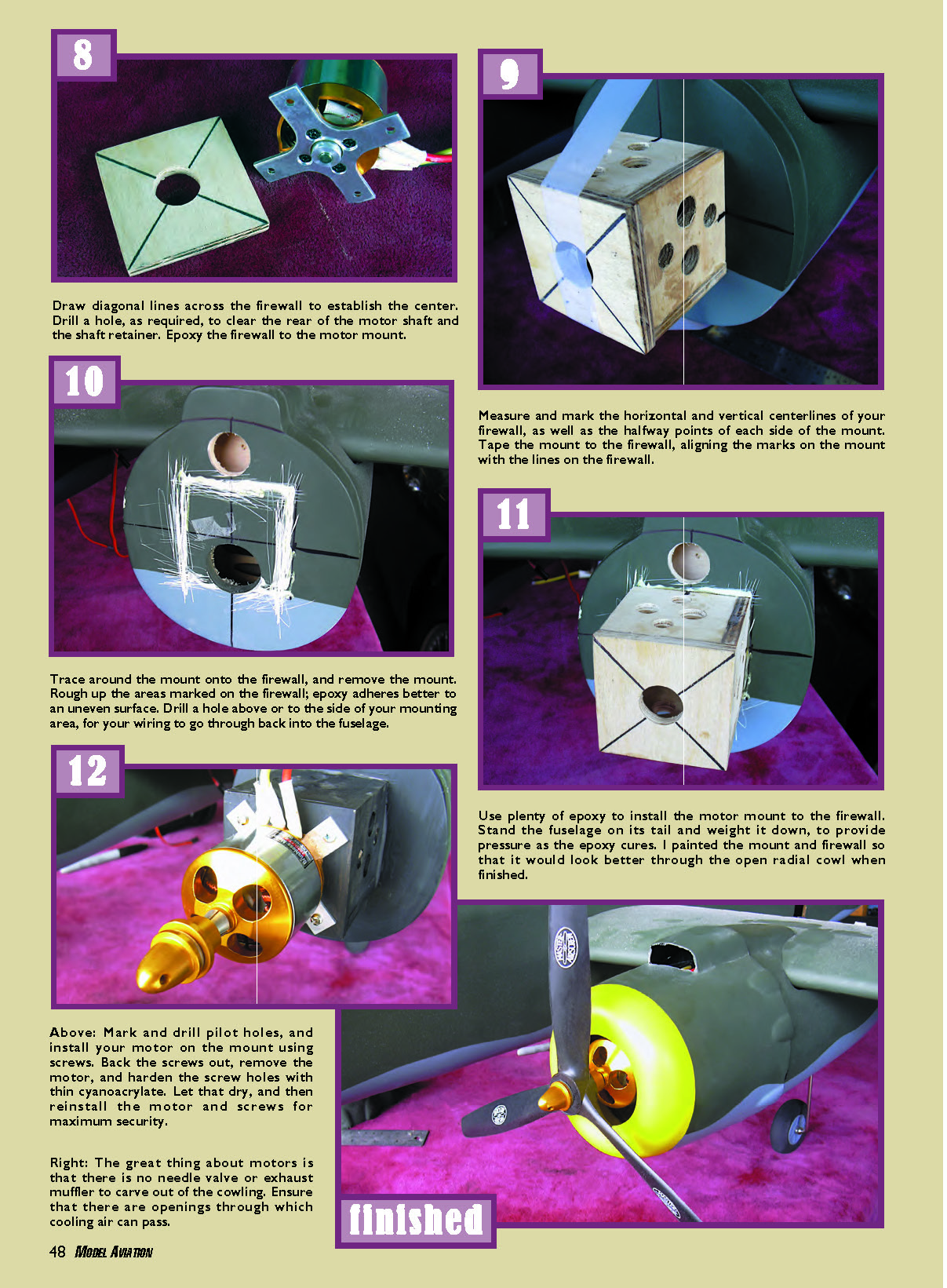
- Draw diagonal lines on the firewall to establish the center point. Drill any needed hole to clear the rear of the motor shaft and shaft retainer.
- Epoxy the firewall to the assembled motor mount, aligning centerlines precisely.
- Measure and mark the horizontal and vertical centerlines of the firewall and the halfway points of each side of the mount. Tape the mount to the firewall, aligning the marks.
- Trace around the mount onto the firewall, then remove the mount. Roughen the areas on the firewall where epoxy will bond; epoxy adheres better to an uneven surface.
- Drill a hole above or to the side of the mounting area for the motor wiring to pass back into the fuselage.
- Use plenty of epoxy to install the motor mount to the firewall. Stand the fuselage on its tail and weight it down to apply pressure while the epoxy cures.
- (Optional) Paint the mount and firewall so they look better through an open cowl or radial opening.
- Mark and drill pilot holes, then install the motor on the mount using screws. Back the screws out and remove the motor, then harden the screw holes with thin cyanoacrylate. Allow the CA to dry, then reinstall the motor and screws for maximum security.
- Ensure there are openings in the cowling for cooling airflow.
Sources:
- Nitro Model Planes — (626) 968-9860 — www.nitroplanes.com
- Midwest Products — (800) 348-3497 — www.midwestproducts.com
Transcribed from original scans by AI. Minor OCR errors may remain.

