

The Performance EDF Experience
by Roger McCormick
Electric-ducted-fan (EDF)-powered models have been around for decades, but the last few years have seen the hobby reach new levels of size and performance, owing largely to the sudden increase of brushless motors, high-discharge lithium battery packs, and advances in lightweight composite construction.
Now that larger ducted-fan systems are more viable, quite a few models that were limited to more expensive turbine power can successfully use electric power. Airplanes that were designed around glow-powered ducted fans can be converted—and in most cases they can surpass previously expected performance.
There are many factors to consider when using EDFs and in choosing the correct airframe and power system for a project. Although numerous manufacturers offer kits and power systems designed to work together, many modelers prefer the challenge of working out power systems and configurations themselves.
Choosing a Fan System
With so many sizes and types of fans available, making selections can be confusing. Properly sizing the fan is crucial to the aircraft’s performance.
Unlike turbines, which use combustion to create thrust, ducted fans accelerate air through the fan unit to produce thrust. Therefore, it is necessary to provide the proper amount of airflow, which means obtaining efficient and correct-size ducting.
When referring to these concepts regarding fans, we use the term “fan swept area,” or FSA; that is the amount of area that the fan’s blades cover. You can calculate this by subtracting the amount of area that the center body section of the fan occupies from the area of the fan shroud.
Luckily the manufacturer typically supplies the FSA. Knowing that, we can look at what is available in terms of inlet area and decide which fan is going to be properly sized for the application.
For the purposes of this article, I will assemble a larger ducted-fan-powered model and use the preceding principles to illustrate the steps I take when deciding what fan unit to use. I’ll be building a Fox-Composites.com BAe Hawk, which has been around in various forms for more than 25 years.
Originally designed around a glow-ducted fan, this jet has also flown successfully with turbine and electric power. It is supplied more or less set up for a 44- to 60-size turbine. The model features a fiberglass fuselage, and the latest version features hollow composite wings.
The kit includes some generic ducting that can be adapted to work with a variety of power setups. I will build the Hawk according to the instructions, except in the areas that require attention for an electric conversion.
The first thing I want to do is examine the supplied ducting and fuselage intakes to determine the amount of combined area with which I have to work. Because of its glow-ducted-fan origins, this model has larger-than-scale intakes that will make powering the Hawk with an electric fan a relatively easy conversion.
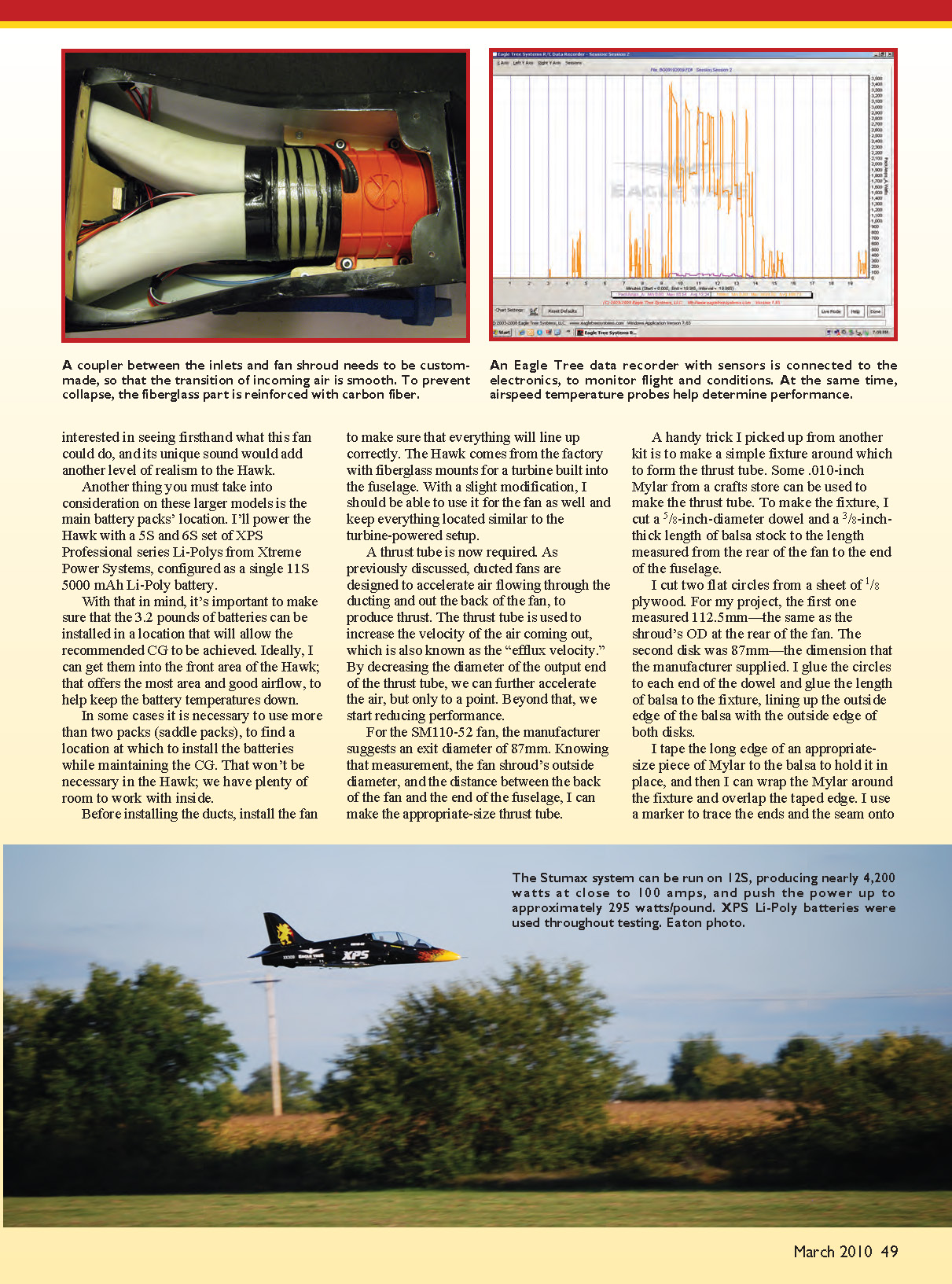
The method I use to calculate the area of the ducting is relatively simple. By tracing the outline of the intake end of the ducting, you can easily calculate the area. Using graph paper with 1/4-inch squares, trace the outline of the inlet side of the ducting. Count the number of squares within the perimeter of the lines. Divide that total by 16, since 1/4-inch-square graph paper is being used. This equals the intake area in square inches. So with 94.5 squares divided by 16, I get 5.91 square inches. Multiplying that by 2 intakes equals an available area of 11.82 square inches total.
Knowing that, I can inspect different fan units and figure out which one will be a good choice. Considering what I want in the way of performance and flight time, there are plenty of options for fans. For this article, I narrowed my search to a few of the newer, higher-powered systems that are near the range required for the Hawk. After considering the EDF setups’ sizes, battery requirements, and ducting necessities, the best candidates were the Schübeler DS-75-DIA HDT, the Stumax SM110-52, and the Tam Jets TJ-100. I also considered what equipment I already had, including batteries and ESCs, to economize as much as possible.
I currently use the Schübeler DS-75 and the TJ-100 and have been satisfied with the performance of both. With that in mind, I decided that for this project I would go with the Stumax SM110-52 setup. I was interested in seeing firsthand what this fan could do, and its unique sound would add another level of realism to the Hawk.
Another thing to consider on these larger models is the main battery packs' location. I'll power the Hawk with a 5S and 6S set of XPS Professional series Li-Polys from Xtreme Power Systems, configured as a single 11S 5000 mAh Li-Poly battery.
With that in mind, it's important to make sure that the 3.2 pounds of batteries can be installed in a location that will allow the recommended CG to be achieved. Ideally, I can get them into the front area of the Hawk; that offers the most area and good airflow, to help keep the battery temperatures down.
In some cases it is necessary to use more than two packs (saddle packs) to find a location at which to install the batteries while maintaining the CG. That won't be necessary in the Hawk; we have plenty of room to work with inside.
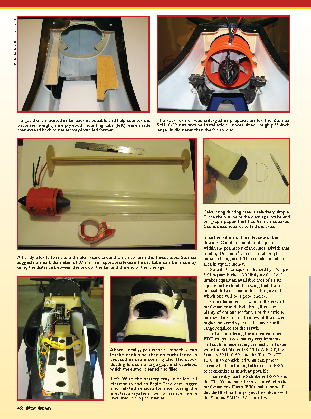
Before installing the ducts, install the fan to make sure that everything will line up correctly. The Hawk comes from the factory with fiberglass mounts for a turbine built into the fuselage. With a slight modification, I should be able to use it for the fan as well and keep everything located similar to the turbine-powered setup.
Thrust Tube Construction
A thrust tube is required. Ducted fans are designed to accelerate air flowing through the ducting and out the back of the fan to produce thrust. The thrust tube is used to increase the velocity of the air coming out, which is also known as the efflux velocity. By decreasing the diameter of the output end of the thrust tube, we can further accelerate the air, but only to a point. Beyond that, we start reducing performance.
For the SM110-52 fan, the manufacturer suggests an exit diameter of 87 mm. Knowing that measurement, the fan shroud's outside diameter, and the distance between the back of the fan and the end of the fuselage, I can make the appropriate-size thrust tube.
A handy trick I picked up from another kit is to make a simple fixture around which to form the thrust tube. Some .010-inch Mylar from a crafts store can be used to make the thrust tube. To make the fixture, I cut a 5/8-inch-diameter dowel and a 3/8-inch-thick length of balsa stock to the length measured from the rear of the fan to the end of the fuselage.
I cut two flat circles from a sheet of 1/8-inch plywood. For my project, the first one measured 112.5 mm—the same as the shroud's OD at the rear of the fan. The second disk was 87 mm—the dimension that the manufacturer supplied. I glue the circles to each end of the dowel and glue the length of balsa to the fixture, lining up the outside edge of the balsa with the outside edge of both disks.
I tape the long edge of an appropriate-size piece of Mylar to the balsa to hold it in place, and then I wrap the Mylar around the fixture and overlap the taped edge. I use a marker to trace the ends and the seam onto the Mylar and then remove the Mylar and cut it to size. When the tube is formed, I carefully sand the seam and edges so they are smooth. I use a lightweight microballoons/epoxy mixture to glue the tube together and to fill any gaps. When installed, the tube is glued to the rear of the fan shroud with the epoxy mixture.
Clear packing tape is sufficient to hold the seam together on the inside and outside while the epoxy cures. When the tube is completed, it can be secured to the back of the fan with clear tape until the epoxy sets.
Installing Ducting and Coupler
I used a pair of curved Lexan scissors to cut and trim the intake ducting so that it fits into the inlets on the fuselage and lines up evenly with the front of the fan. Tape the ducting into place and make a coupler section to connect the fan to the ducts.
I use poster board to create a template for a short coupler piece to join the fan and ducts, leaving an extra 1/4 inch on each end to overlap when it's glued together. Then I trace it onto a .010-inch-thick fiberglass sheet that I later roll into a tube. I use CA to bond the overlap, and then I epoxy two layers of 1/2-ounce fiberglass cloth over the seam.
After that dries, I wrap it with carbon tow to make it even stronger. I don't want it to collapse when I start pulling a vacuum on the ducting.
With the coupler secured to the fan and ducting and everything checked for alignment, I glue the ducting to the inlets on the fuselage with a mixture of epoxy and microballoons. On the inside wall of the fuselage, I used 1/2-ounce fiberglass cloth to cover the overlap and help secure the inner side of the ducting.
Ideally you want a smooth and clean intake radius to reduce turbulence of incoming air. The stock ducting left some large gaps and overlaps, so clean these up and remove any excess with a Dremel tool. Then fill with body filler to blend it in. I'll use my airbrush to repaint the intakes.
Battery Tray and ESC Placement
The batteries need a tray. The kit came with two plywood sections that glue to the bottom of the fuselage the length of the nose section to reinforce it. I added triangle stock to the sides, and I put a piece of 3/16-inch light plywood over it to act as the battery tray.
The most common mounting solution for the ESC in the majority of ducted fans is to put it behind the engine in a fairing so that it receives plenty of cooling air. That approach won't work with the SM110-52 and its rear-rotor design.
To get proper airflow over the ESC, I mounted it on the top of the ducting under the rear hatch area. The Hawk has intake scoops molded into the fuselage, as the full-scale aircraft does, so I use those to get air into the speed controller.
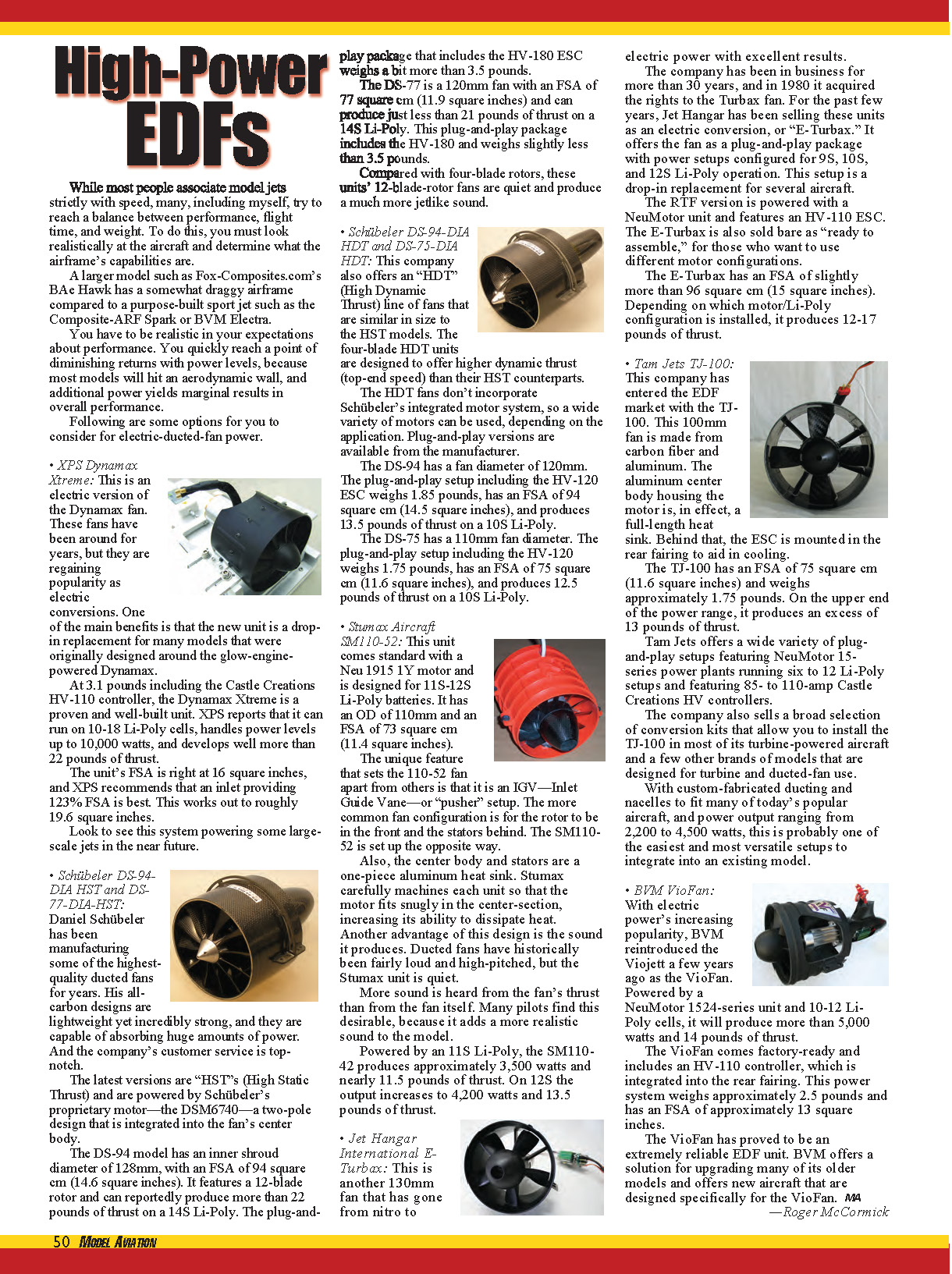
I also used a piece of lightweight plastic to close off the underside of the hatch and cut out a section to direct the air directly over the ESC, where it's then drawn out the rear of the fuselage. In addition, I mounted a temperature probe on the ESC so I can monitor its temperature with the Eagle Tree Systems data-logging system.
Static Testing and Power Rule of Thumb
As a rule of thumb, 250 watts per pound is a good figure to apply when dealing with ducted-fan models; we call that number "good performance." Take care when static-testing any aircraft; safety glasses are a good idea.
With the Hawk secured and the Eagle Tree transmitting information back to the laptop via the Seagull wireless setup, I ran the fan to somewhat simulate a typical flight by varying the throttle and working the control surfaces for approximately five minutes, with a short cooldown period at low throttle for the motor.
The Eagle Tree system reported 3,429 watts at 83.54 amps. The model's final weight at 13.8 pounds works out to 248.5 watts per pound, so we should be good on power.
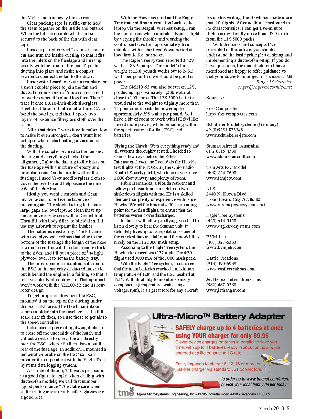
The SM110-52 can also be run on 12S, producing approximately 4,200 watts at close to 100 amps. The 12S 5000 batteries would raise the weight to slightly more than 14 pounds and push the power up to approximately 295 watts per pound. So I have a bit of room to work with if I feel like I need more power, while remaining within the specifications for fan, ESC, and batteries.
Flying the Hawk
With everything ready and all systems thoroughly tested, I headed to Ohio a few days before the E-Jets International event so I could do the Hawk's test flights at the TORKS (The Ohio Radio Kontrol Society) field, which has a very nice 1,000-foot runway and plenty of room.
Pablo Hernandez, a Florida resident and fellow pilot, was kind enough to do two shakedown flights with me. He is a skilled flier and has plenty of experience with larger Hawks. We set the timer at 4:30 as a starting point for the first flights, to ensure that the batteries weren't overdischarged.
In the air with other jets flying, you had to listen closely to hear the Stumax unit. It definitely lives up to its reputation as one of the quietest fans available, and the model flew nicely on the 11S 5000 mAh setup.
According to the Eagle Tree system, the Hawk's top speed was 137 mph. The 4:30 flight used 3,800 mA of the 5,000 mAh pack.
With the Eagle Tree system, I could see that the main batteries reached a maximum temperature of 128°F and the ESC peaked at 121°F. With its ability to monitor so many components (temperature, watts, amps, voltage, RPM), it's a great tool for any aircraft.
As of this writing, the Hawk has made more than 10 flights. After getting accustomed to its characteristics, I can get five-minute flights using slightly more than 4,000 mAh from the 11S 5,000 packs.
With the ideas and concepts I've presented in this article, you should understand the basic principles of sizing and implementing a ducted-fan setup. If you do have questions, the manufacturers I have mentioned are happy to offer guidance so that your ducted-fan project is a success.
Roger McCormick [email protected]
Sources
- Fox-Composites — http://fox-composites.com
- Schübeler Modellssysteme (Germany) — +49 (0)5251 873348 — www.schuebeler-jets.com
- Stumax Aircraft (Australia) — +61 2 8819 4330 — www.stumaxaircraft.com
- Tam Jets R/C Model — (408) 224-7600 — www.tamjets.com
- XPS — 2440 N. Kiowa Blvd., Lake Havasu City AZ 86403 — www.xtremepowersystems.net
- Eagle Tree Systems — (425) 614-0450 — www.eagletreesystems.com
- BVM Jets — (407) 327-6333 — www.bvmjets.com
- Castle Creations — (913) 390-6939 — www.castlecreations.com
- Jet Hangar International, Inc. — (562) 467-0260 — www.jethangar.com
Transcribed from original scans by AI. Minor OCR errors may remain.

