
The Tail of Two Airplanes
Although I own more than 60 flying models, there are only a couple that I use extensively during most of the flying season: my No. 1 and No. 2 RC aerobatics (Pattern) competition airplanes. This is mostly because I need to practice a great deal — I don't have the world’s top Pattern pilots' natural talents.
I also fly them a lot because nothing performs as well as a modern, well-trimmed Pattern aircraft. However, Pattern models are difficult to appreciate because they are flown at high altitudes. Purpose-built to perform gracefully, they typically do that with exhausting repetition.
Larger sport-scale airplanes, especially warbirds, present well and relate to the general public. Many people can identify a P-51 Mustang and have seen one fly. These aircraft are normally bigger and more impressive; people and pilots alike enjoy watching them perform.
I travel often to visit and fly with other clubs in my district. Everyone I visit is kind enough to politely watch my Pattern airplane do its stuff—once. More than once? Not so much. It finally occurred to me that flying Pattern maneuvers with a larger sport-scale warbird might make things less boring. But could it be made to happen?
When built to sport specifications, these models will fly but will not always perform. To perform, sometimes they must be modified, trimmed, and powered as Pattern aircraft would be. “Patternized” airplanes exhibit amazing flying abilities that will surprise even the most experienced pilot. Although this “tail” is about my two models, all of the techniques here can be used to improve any sport aircraft’s performance. This article contains some how-tos, but its focus is on recognizing your airplane’s performance or structural deficiencies and using some remedies to fix them. My test subjects are the two models I take with me from show to show. Warning: the following modifications and trimming techniques are the ways I did it. There are other ways to achieve these performance goals, but I know these work well.
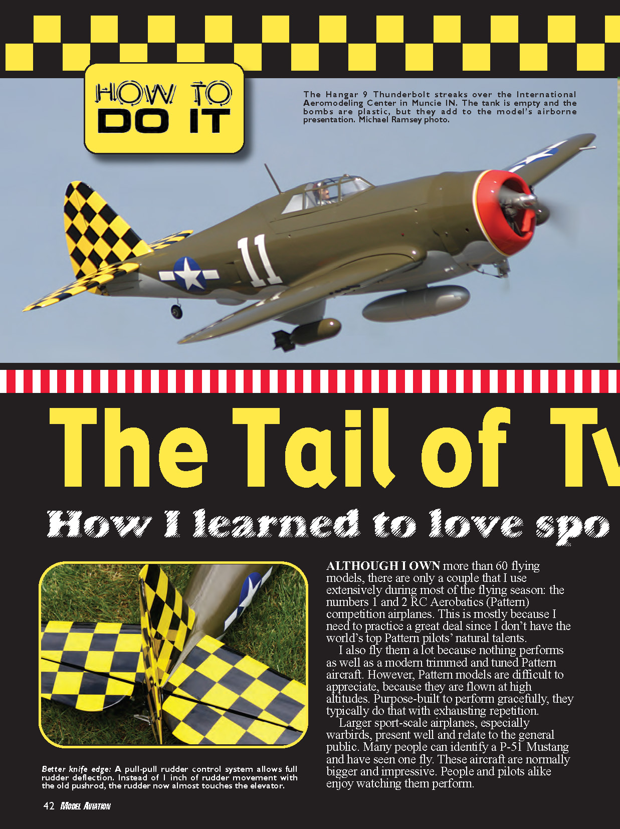
Large warbirds can be crowd pleasers. No matter where it is flown, Great Planes’ Curtiss P-6E Hawk in its “Presidential Inauguration” colors draws attention and questions from spectators. Likewise, the Hangar 9 P-47 Thunderbolt 150 looks massive with bombs, an external fuel tank, retracts, and flaps and gets more than its share of attention. Both models fly well as sport aircraft but have severe limitations as true performers. In sport trim the Hawk was underpowered, climbed slowly, couldn’t hold a vertical, wouldn’t roll well, dropped the right wing with heavy elevator input, corkscrewed in loops, had too much adverse yaw, and wouldn’t climb inverted or hold a knife edge. But it looked great flying by, and the landings were slow-motion spectaculars.
Let’s see what can be done.
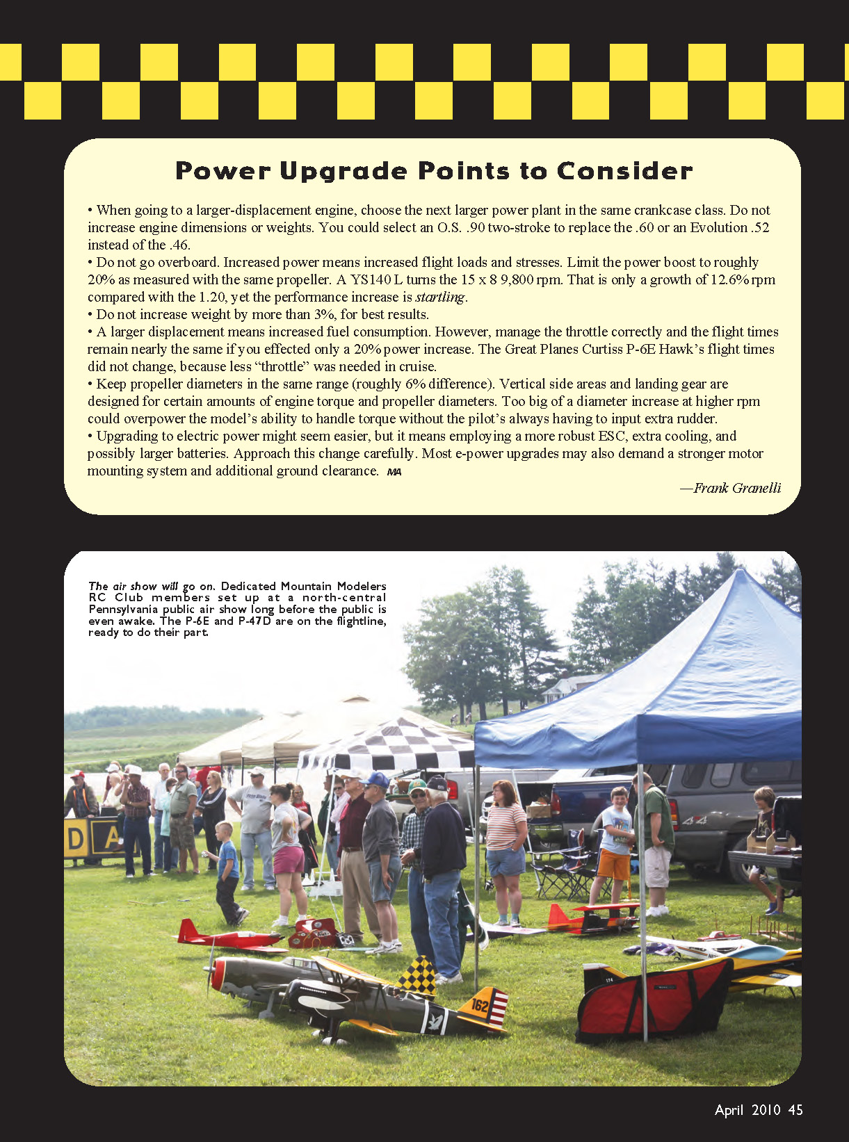
Power Upgrade Points to Consider
- When going to a larger-displacement engine, choose the next larger power plant in the same crankcase class. Do not increase engine dimensions or weights significantly. For example, you might select an O.S. .90 two-stroke to replace a .60, or an Evolution .52 instead of a .46.
- Do not go overboard. Increased power means increased flight loads and stresses. Limit the power boost to roughly 20% as measured with the same propeller. A YS 140L, for example, can turn a 15x8 prop around 9,800 rpm — only about a 12–13% increase over some smaller engines, yet the performance increase can be startling.
- Do not increase weight by more than about 3% for best results.
- A larger displacement means increased fuel consumption. However, with correct throttle management flight times remain nearly the same if you only effect a ~20% power increase. In my Hawk the flight times did not change because less throttle was needed in cruise.
- Keep propeller diameters in the same range (roughly within about 6% difference). Vertical side area and landing gear are designed for certain amounts of engine torque and prop-diameter. Too large a diameter increase at higher rpm could overpower the model’s ability to handle torque without the pilot constantly adding rudder.
- Upgrading to electric power might seem easier, but it usually means a more robust ESC, additional cooling, possibly larger batteries, stronger motor mounts, and extra ground clearance. Approach this change carefully.
— Frank Granelli
Great Planes P-6E Hawk
The Hawk looked great but needed more power for Pattern-like verticals and energy. The original engine was the reliable O.S. Max 1.20 Surpass III. It’s a great sport powerplant, but it was not designed to provide a 14-pound biplane with Pattern-like performance. Takeoff runs were long, initial climb rate was too low for tighter air-show venues, and verticals were impossible to hold.
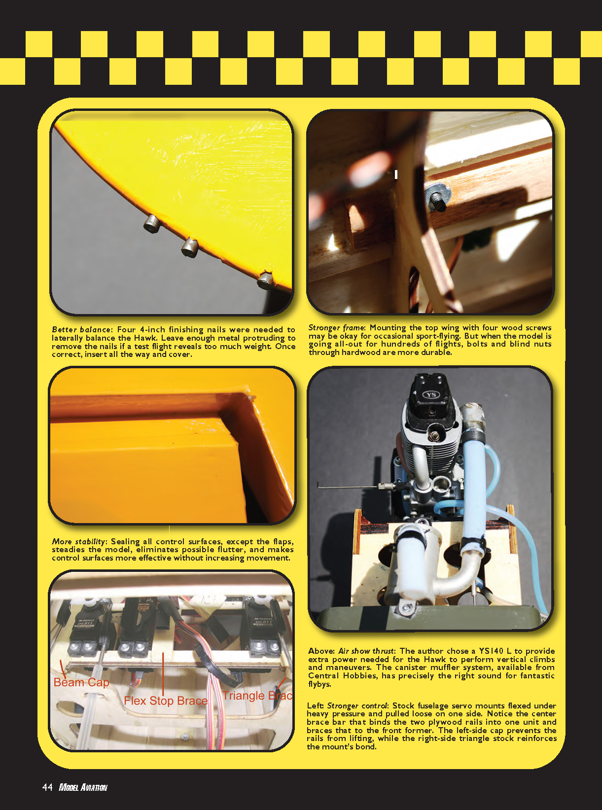
The P-6E needed a more powerful engine that was lightweight and fit in the same space. The O.S. 1.20 two-stroke would have enough power but wouldn’t sound or look right. Larger sport four-strokes were too big and heavy to fit without cutting the cowl badly. A YS 140L proved to be the perfect choice: it fit in the same space and mounts as the O.S. 1.20 with only minor cowl cutting. Central Hobbies sells an NMP sport muffler system that fit perfectly while exhausting under the cowling; I did not even have to alter the throttle pushrod. The 1.20 and 1.40 weighed essentially the same.
The result was a power increase (using Powermaster YS/Saito 20-20 fuel) from about 8,700 rpm on an APC 15x8 prop to around 9,300 rpm on a 16x10 APC — a big increase at the top end. The payoff was immediate: takeoff runs under 50 feet, initial climb rate more than doubled, and small-field operations became trivial. The model could hold a vertical up-line, enabling stall turns, Top Hats with 1/4 or 1/2 rolls, Figure Ms, and Humpty Bumps. Level knife-edge flight went from nearly impossible to something that could be trimmed. Best of all, the airplane would climb while inverted and could perform outside loops and avalanches from the bottom.
Increasing power is a prerequisite for the vertical up-lines needed, but it’s only the start. Setting up the airframe is even more critical.
Sealing aileron and elevator gaps was a key solution. Even if you cannot see through the aileron/wing gap, air still passes through it. The aileron and wing then act as two separate surfaces, reducing aileron effectiveness. Use clear or matching covering to seal the underside of the gap — do the same for elevators. Sealing gaps boosts control effectiveness, helps prevent flutter, and stops annoying wing drops on sharp pullouts. On the Hawk, sealing gaps increased roll rate without noticeably increasing adverse yaw and eliminated the right-wing drop on pullouts.
If loops corkscrew, the most common cause is poor lateral balance. Every airplane must be balanced laterally for good aerobatic performance. Balance laterally as the last step indoors before going to the field: assemble the model, remove the prop, run thin nylon fishing line through the rudder/fin gap under the top hinge and under the crankshaft, and lift the model by those lines. The model will probably drop a wing toward the muffler side. Use finishing nails taped to the opposite wingtip until the aircraft balances and remains level. Once satisfied, insert the nails into the wingtip (leaving 1/4 inch exposed), secure with CA, and patch the area with matching covering.
For an even more sensitive test, run the line under the bottom rudder hinge rather than the top one. This can achieve a finer lateral balance, though on sport airplanes the practical difference is often small.
Adverse yaw: the Hawk’s ailerons were only on the top wing, so adverse yaw was noticeable. The down aileron has more drag, causing the nose to yaw opposite the intended roll. Many modern radios offer a differential function; try that first. However, unless you have a high-end transmitter with separate per-channel differential, the equal differential is applied in both directions and may overcorrect one side while fixing the other.
My method: identify which roll direction needs help most. Fly a stabilized wings-level vertical up-line and apply full aileron in each direction to observe tail wiggle. Use the transmitter’s travel function to adjust aileron travel in only the problem direction, matching the travel the differential had provided. Then remove the equal differential function. Repeat for the other direction. This dialed-in approach preserves roll quality in both directions without killing roll performance one way while fixing the other.
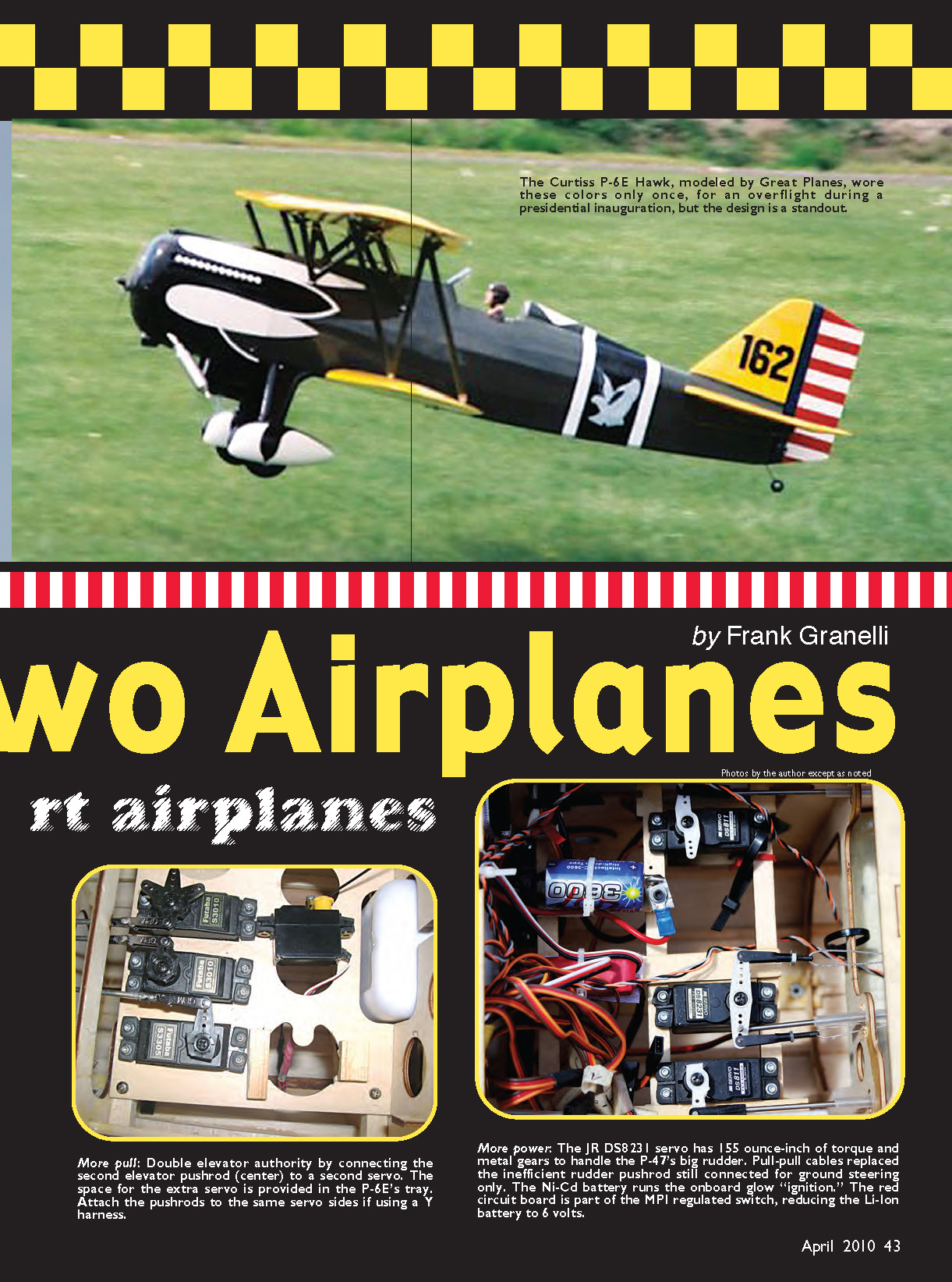
Structural reinforcements and servo upgrades: aerobatic schedules with the larger engine increase airframe stress. On the Hawk I installed a second elevator servo to add control authority and trimming capability, and I replaced cabane wood screws with 4-40 blind nuts and bolts bonded in place with thread-locking compound. Examine your model for weak points and reinforce firewall gussets, servo mounts, or cabane attachments as needed. Use stronger digital servos on control surfaces if you’ve increased power; I upgraded the Hawk’s servos to roughly 85 oz-in for the control surfaces and a 155 oz-in digital servo for the rudder. Verify that your flight battery can support the upgraded servos.
Great Planes P-47D Thunderbolt
The Thunderbolt already had a more powerful Saito 2.20 installed in place of the 1.50–1.80 originally specified. Flying 300–400 foot up-lines was routine, but the small ailerons and their far-outboard placement on the 81-inch span wing caused slow roll rates and pronounced adverse yaw in both directions. The complex rudder control system limited rudder movement to only 1 inch, making knife-edge flight impossible. With higher engine torque and a larger prop, the up-line bent left during full-power verticals; the fuselage servo mount was flexing.
First fix: the rudder. I cut the control rod just beyond the tailwheel connection and installed a pull-pull system directly to the rudder, which required internal fuselage work. Be mindful of geometry: the total width of the rudder attachment points must match the servo arm length, and the cables should exit the fuselage where the width equals that distance so the cables run straight from servo to rudder horn. Kinks prevent perfect centering.
After the pull-pull conversion, the Thunderbolt climbed in knife-edge. However, fuselage servo mounts needed reinforcing: I braced the mounts, added a cap to prevent the rails from lifting away from side fuselage braces, used triangle stock where appropriate, and tied the two rails together with a hardwood brace glued to a former to eliminate mid-rail flex and pitch hunting.
I had an engine idling reliability issue: the big four-stroke mounted upside-down pooled raw fuel in the head area at low rpm, extinguishing the glow plug. To cure this I installed a Maxx Products International Super Glow MX9900 on-board glow-plug driver. It can be set to light the glow plug at any throttle setting, uses a single-cell 1300 mAh Ni-Cd battery, and works from the receiver’s throttle port. Since installation in 2008 I’ve had no engine failures at idle.
Sealing aileron gaps increased roll rate on the P-47 even more than on the Hawk. Closing gaps tends to help more on symmetrical or semisymmetrical wings than on flat-bottom airfoils — the P-47’s semisymmetrical wing responded very well. I set aileron movement near 1 inch and adjusted for adverse yaw. On these aircraft a good aerobatic roll rate often matches the old standard of three rolls in five seconds.
Sealing control-surface gaps also eliminated the Thunderbolt’s left wing drop and seemed to increase overall lift. The airplane was a “floater” in ground effect, so to regain precise landing spots I increased flap deployment by about 5°. I trimmed adverse yaw using the same methods I used on the Hawk; it just took more flights.
After the changes the Thunderbolt still flew docilely but now performed slow rolls and snaps with precision. Loops tracked well and vertical figure eights behaved. Inverted flight required only a touch of down elevator but tracked true. Because the P-47D was so honest, I moved the CG 1/8 inch aft of the rearmost setting to improve snap rolls and spins while keeping the airplane controllable — a tweak I do not recommend until you have several hundred flights and know the model well.
Trimming and Final Setup
Trimming takes time. Expect roughly 40 flights to get the airplane well-trimmed; the NSRCA trim chart suggests about 100 flights and adjustable wing/stabilizer incidences for exact Pattern setups. The NSRCA guide is excellent but can be overkill for some sport models. I’ve found a few trim adjustments to be the most important for a sport-type airplane’s optimum aerobatic performance:
- Knife-edge trim
- Sport airplanes will tend to “walk” in knife-edge flight. With rudder applied in knife-edge or slow rolls, the aircraft usually pulls toward the belly. Moving the CG (usually rearward) or adjusting wing incidence (with shims if possible) will usually help. Try mixing rudder to elevator with a direct mix (no curves). The goal is straight knife-edge flight. If the mix requires fewer than about 20 elevator points, that’s acceptable. More than 20 points can upset other maneuvers, so change CG or incidence slightly to reduce the required mix.
- Eliminate roll coupling
- Roll coupling occurs when rudder input also rolls the wings. Point rolls and stall turns require little or no coupling. Mix opposite aileron to rudder if the coupling is proverse (in the rudder’s direction), or mix aileron with rudder if coupling is adverse. The ideal condition results in a slightly descending flat turn on rudder alone.
- Down-line trim
- Take the airplane high, go to idle, and push the nose down to 90°. Watch the track. Many sport models will begin to pull out as airspeed increases. Eliminate this by mixing a small amount of down elevator only at low throttle. If your transmitter cannot make a mix active only at idle or very low throttle, skip this unless the pullout is large (roughly 10°). If so, you might have to reduce wing incidence — be careful; start with a very small change (around 1/8°).
- Up-line/right-rudder tendencies
- Most sport airplanes won’t pull to the canopy in vertical up-lines, but you will likely need to add some right rudder in up-lines. Adjusting engine thrust line is a hassle; instead try curve mixing (step): one to two points of right rudder at half throttle, increasing to four to five points at full power. This helps keep vertical up-lines straight and reduces pilot workload when transitioning between maneuvers.
A final note on practice: trimming and getting these models to perform well requires time and flights. If a giant biplane with a flat-bottom airfoil can be improved to near-Extra 300 performance, so can your sport airplane. Try it once, and you may never want to fly a stock, out-of-trim sport airplane again.
MA
Frank Granelli [email protected]
Sources:
- Great Planes
(217) 398-3630 www.greatplanes.com
- Hangar 9
(800) 338-4639 www.hangar-9.com
- Central Hobbies
(406) 259-9004 www.centralhobbies.com
- "From the Ground Up" index
www.modelaircraft.org/mag/FTGU/titlespageftgu.htm
- Maxx Products International
(800) 416-6299 www.maxxprod.com
- National Society of Radio Controlled Aerobatics
Transcribed from original scans by AI. Minor OCR errors may remain.

