
How-to: Install Retractable LANDING GEAR
by Chuck Snyder
Tips for installing gear in your Scale model
I suspect most modelers have their first experience with retractable landing gear in some form of sport or aerobatic model. In my case it was probably with one of the 1970s-vintage pattern airplanes such as a Kaos or Dirty Birdy.
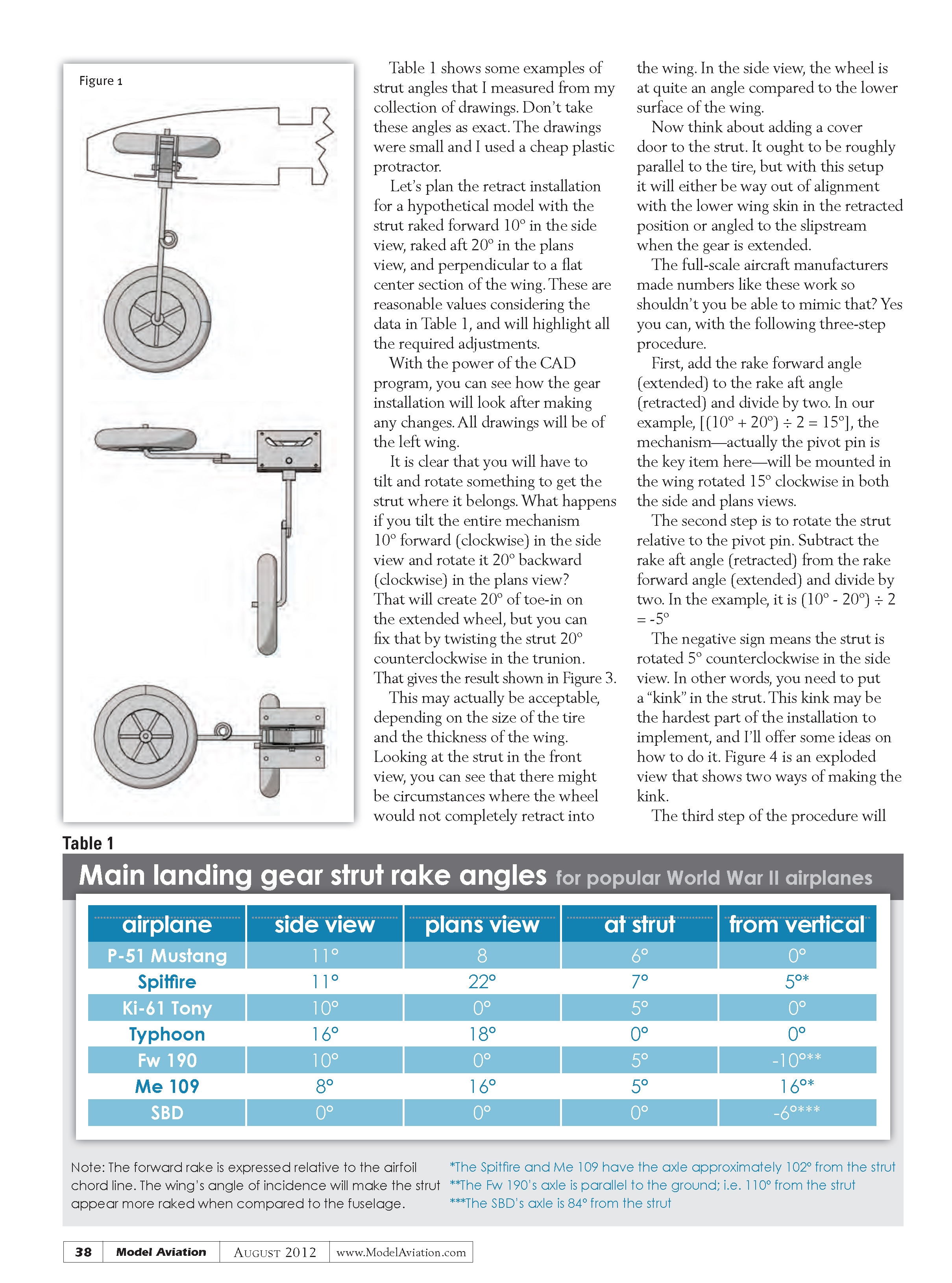
The installation was straightforward: mount the main-gear retract unit perpendicular to the centerline of the model and parallel to the lower surface of the wing. The nose gear (and this is the last time I’ll mention that item) was usually mounted directly to the firewall.
Figure 1 is a 3-D CAD drawing (top, front, and side view) of how the main-gear mechanism, strut, and wheel look in the extended and retracted positions for this type of installation. The mechanism is elegant in its simplicity, and everything is at right angles to everything else. In keeping with the concept that right angles are good, the strut swings through 90°. This works out nicely for sport models.
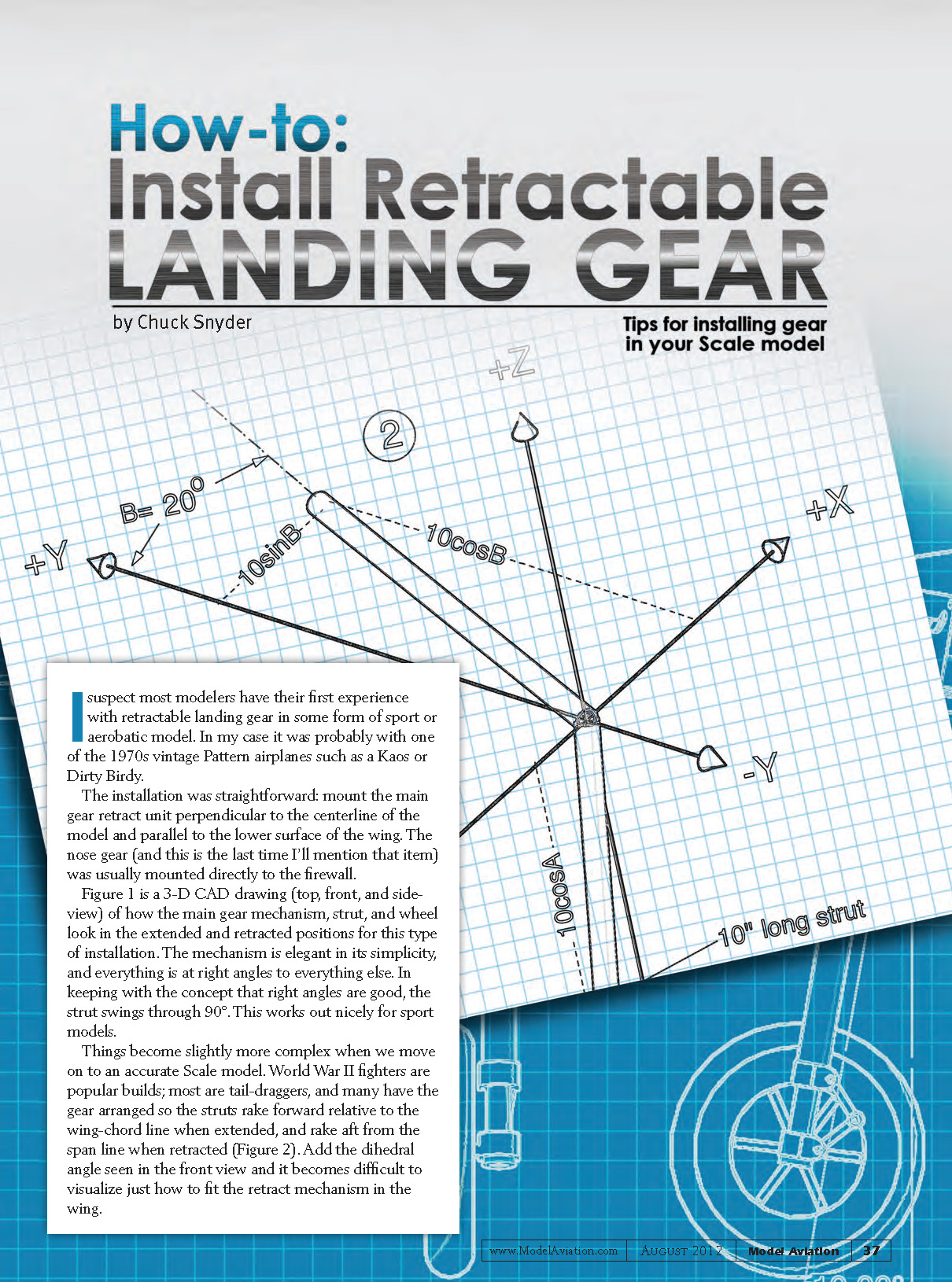
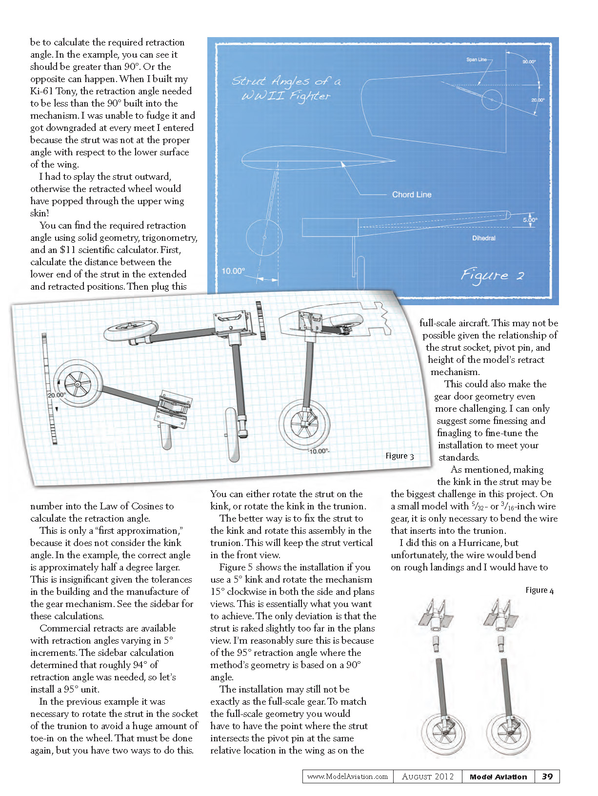
Things become slightly more complex when we move on to an accurate scale model. World War II fighters are popular builds; most are tail-draggers, and many have gear arranged so the struts rake forward relative to the wing-chord line when extended, and rake aft from the span line when retracted (Figure 2). Add the dihedral angle seen in the front view and it becomes difficult to visualize just how to fit the retract mechanism in the wing.
Table 1 shows some examples of strut angles that I measured from my collection of drawings. Don't take these angles as exact. The drawings were small and I used a cheap plastic protractor.
Let's plan the retract installation for a hypothetical model with the strut raked forward 10° in the side view, raked aft 20° in the plan view, and perpendicular to a flat center section of the wing. These are reasonable values considering the data in Table 1, and will highlight all the required adjustments.
With the power of the CAD program, you can see how the gear installation will look after making any changes. All drawings will be of the left wing.
It is clear that you will have to tilt and rotate something to get the strut where it belongs. What happens if you tilt the entire mechanism 10° forward (clockwise) in the side view and rotate it 20° backward (clockwise) in the plan view? That will create 20° of toe-in on the extended wheel, but you can fix that by twisting the strut 20° counterclockwise in the trunnion. That gives the result shown in Figure 3.
This may actually be acceptable, depending on the size of the tire and the thickness of the wing. Looking at the strut in the front view, you can see that there might be circumstances where the wheel would not completely retract into the wing. In the side view, the wheel is at quite an angle compared to the lower surface of the wing.
Now think about adding a cover door to the strut. It ought to be roughly parallel to the tire, but with this setup it will either be way out of alignment with the lower wing skin in the retracted position or angled into the slipstream when the gear is extended.
The full-scale aircraft manufacturers made numbers like these work, so shouldn't you be able to mimic that? Yes you can, with the following three-step procedure.
- Add the rake-forward angle (extended) to the rake-aft angle (retracted) and divide by two.
- Example: (10° + 20°) ÷ 2 = 15°.
- The mechanism—actually the pivot pin is the key item here—will be mounted in the wing rotated 15° clockwise in both the side and plan views.
- Rotate the strut relative to the pivot pin. Subtract the rake-aft angle (retracted) from the rake-forward angle (extended) and divide by two.
- Example: (10° - 20°) ÷ 2 = -5°.
- The negative sign means the strut is rotated 5° counterclockwise in the side view. In other words, you need to put a "kink" in the strut. This kink may be the hardest part of the installation to implement; see ideas and an exploded view in Figure 4.
- Calculate the required retraction angle.
- In the example, you can see it should be greater than 90°. Or the opposite can happen: when I built my Ki-61 Tony, the retraction angle needed to be less than the 90° built into the mechanism. I was unable to fudge it and got downgraded at every meet I entered because the strut was not at the proper angle with respect to the lower surface of the wing. I had to splay the strut outward, otherwise the retracted wheel would have popped through the upper wing skin!
You can find the required retraction angle using solid geometry, trigonometry, and an $11 scientific calculator. First, calculate the distance between the lower end of the strut in the extended and retracted positions. Then plug this number into the Law of Cosines to calculate the retraction angle.
This is only a "first approximation," because it does not consider the kink angle. In the example, the correct angle is approximately half a degree larger. This is insignificant given the tolerances in the building and the manufacture of the gear mechanism. See the sidebar for these calculations.
Commercial retracts are available with retraction angles varying in 5° increments. The sidebar calculation determined that roughly 94° of retraction angle was needed, so let's install a 95° unit.
In the previous example it was necessary to rotate the strut in the socket of the trunnion to avoid a huge amount of toe-in on the wheel. That must be done again, but you have two ways to do this:
- Rotate the strut on the kink.
- Rotate the kink in the trunnion.
The better way is to fix the strut to the kink and rotate this assembly in the trunnion. This will keep the strut vertical in the front view.
Figure 5 shows the installation if you use a 5° kink and rotate the mechanism 15° clockwise in both the side and plan views. This is essentially what you want to achieve. The only deviation is that the strut is raked slightly too far in the plan view. I'm reasonably sure this is because of the 95° retraction angle where the method's geometry is based on a 90° angle.
The installation may still not be exactly as the full-scale gear. To match the full-scale geometry you would have to have the point where the strut intersects the pivot pin at the same relative location in the wing as on the full-scale aircraft. This may not be possible given the relationship of the strut socket, pivot pin, and height of the model's retract mechanism.
This could also make the gear-door geometry even more challenging. I can only suggest some finessing and finagling to fine-tune the installation to meet your standards.
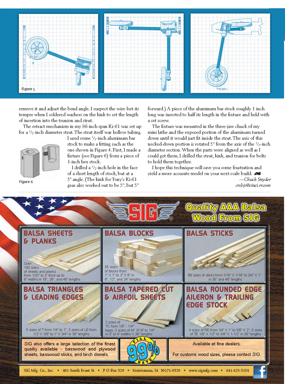
As mentioned, making the kink in the strut may be the biggest challenge in this project. On a small model with 5/32- or 3/16-inch wire gear, it is only necessary to bend the wire that inserts into the trunnion.
I did this on a Hurricane, but unfortunately, the wire would bend on rough landings and I would have to remove it and adjust the bend angle. I suspect the wire lost its temper when I soldered washers on the kink to set the length of insertion into the trunnion and strut.
The retract mechanism in my 86-inch-span Ki-61 was set up for a 1/2-inch-diameter strut. The strut itself was hollow tubing. I used some 1/2-inch aluminum bar stock to make a fitting such as the one shown in Figure 4. First, I made a fixture (see Figure 6) from a piece of 1-inch hex stock.
I drilled a 1/2-inch hole in the face of a short length of stock, but at a 5° angle. (The kink for Tony's Ki-61 gear also worked out to be 5°, but 5° forward.) A piece of the aluminum bar stock roughly 1 inch long was inserted half its length in the fixture and held with a set screw.
The fixture was mounted in the three-jaw chuck of my mini lathe and the exposed portion of the aluminum turned down until it would just fit inside the strut. The axis of this necked-down portion is rotated 5° from the axis of the 1/2-inch-diameter section. When the parts were aligned as well as I could get them, I drilled the strut, kink, and trunnion for bolts to hold them together.
I hope this technique will save you some frustration and yield a more accurate model on your next scale build.
—Chuck Snyder [email protected]
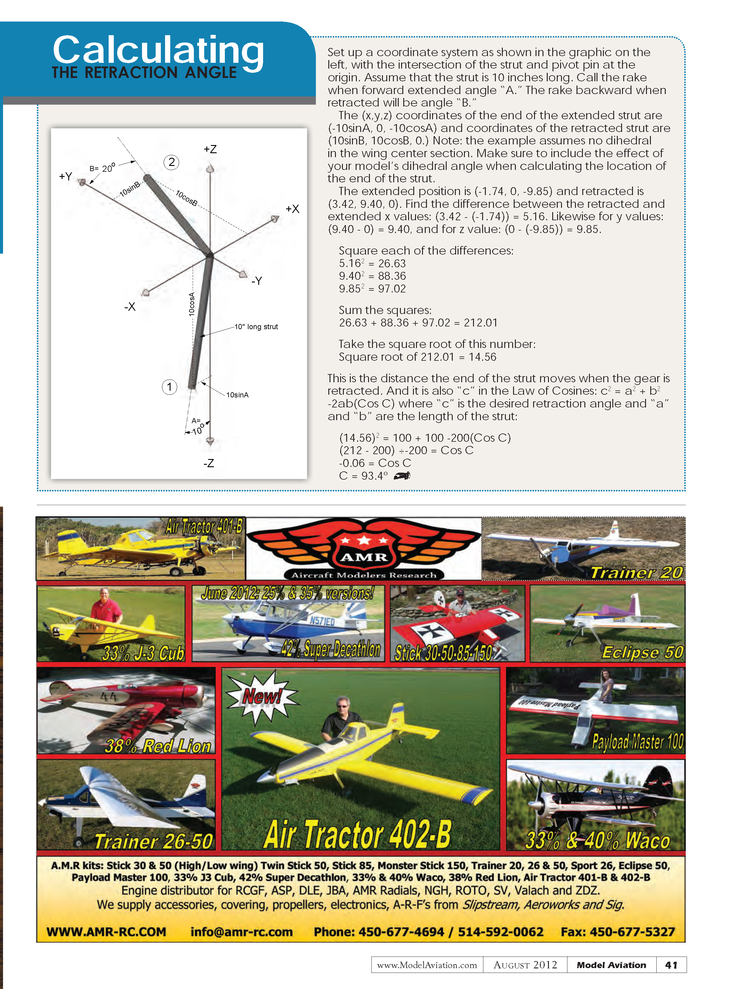
Calculating THE RETRACTION ANGLE
Set up a coordinate system with the intersection of the strut and pivot pin at the origin. Assume the strut is 10 inches long. Call the rake when forward (extended) angle A, and the rake backward (retracted) angle B. Note: the example assumes no dihedral in the wing center section. Make sure to include the effect of your model's dihedral angle when calculating the location of the end of the strut.
The (x, y, z) coordinates of the end of the extended strut are:
- (-10 sin A, 0, -10 cos A)
The coordinates of the retracted strut are:
- (10 sin B, 10 cos B, 0)
For the example (A = 10°, B = 20°) the coordinates evaluate to:
- Extended: (-1.74, 0, -9.85)
- Retracted: (3.42, 9.40, 0)
Find the differences (retracted minus extended):
- Δx = 3.42 - (-1.74) = 5.16
- Δy = 9.40 - 0 = 9.40
- Δz = 0 - (-9.85) = 9.85
Square each difference:
- 5.16^2 = 26.63
- 9.40^2 = 88.36
- 9.85^2 = 97.02
Sum the squares:
- 26.63 + 88.36 + 97.02 = 212.01
Take the square root to get the distance c the strut end moves:
- c = sqrt(212.01) = 14.56
Use the Law of Cosines to find the retraction angle C (where a = b = 10 in):
- c^2 = a^2 + b^2 - 2ab cos C
- 14.56^2 = 10^2 + 10^2 - 2·10·10·cos C
- 212.01 = 200 - 200 cos C
- 200 cos C = 200 - 212.01 = -12.01
- cos C = -12.01 / 200 = -0.06005
- C = arccos(-0.06005) ≈ 93.4°
So the retraction angle required in this example is approximately 93.4°, which suggests selecting the nearest commercial unit (e.g., 95°) if available.
Transcribed from original scans by AI. Minor OCR errors may remain.

