
How to Make: High-Performance Props
Custom-made props for a particular airplane/engine combination can make your racer fly faster. In this two-part article the author discusses, this month, considerations that determine the parameters of the special prop. Development of the blank and carving of the propeller will be covered in the July issue. ■ Harold deBolt
High-Performance Props
TODAY'S hobby shops offer us the most simple necessities. Usually, they are ready for use, or at least in kit form. But lacking is something from which we can make our own propellers.
We have a very wide variety of "ready mades" available, but we are restricted to what is offered. Very often, propeller requirements can be very particular as to sizes needed, and the maximum efficiency desired of them. If propeller experimentation is desired, considerable design research and woodworking knowledge is necessary. The only answer to the problem has been "reworking" production props, a time-consuming procedure that often results in an inferior product.
The shortcomings of reworking are numerous. Most often, there is not enough material to allow the desired changes. Changes in the amounts and types of pitch are restricted by the original design. The fixed design also prevents us from obtaining a different blade shape. Reworking allows us to do nothing more than alter someone else's propeller design, which may be far from the ultimate.
Reworking can improve performance. Have you wondered if production propellers are anywhere near perfection, or noticed that they have changed little over many years? Does this mean that propeller design reached perfection years ago? There is no such thing as perfection; what seems "perfect" today, always is improved tomorrow. Each year seems to bring better engines. Maximum power is obtained at much higher rpm than ever before. Since the prop controls rpm, could changes in prop design take better advantage of engine improvements?
Airplane performance is a direct result of the power available. Assuming that prop pitch is correct for the speed of the airplane, power available is a combination of the horsepower of the engine, and the thrust developed by the propeller. So propeller efficiency is important. A very powerful engine turning a very inefficient propeller is an excellent cooling fan! An efficient prop for one type of an engine would be less than the ultimate on a different engine. Each particular type of engine requires a different style of propeller.
If you design your airplane from scratch you may reasonably have the engine-propeller combination correct before attempting to improve the airplane. Most modelers throw up their hands at the suggestion to make their own propellers. However, the chore is relatively simple and inexpensive. It does require some skill and there is no limit to experimentation. The ultimate found — duplication problem? I believe one can produce a propeller from scratch in less than two hours. I will explain basic design parameters that can be used; I will also provide information needed to produce any prop you wish in your workshop.
Required tools and inexpensive materials are common. Check the high school industrial arts teacher — he might be happy to fabricate prop blanks as a class project.
Before commencing you need to know diameter, blade width, blade shape and pitch. You can change some parameters later, but note results; proper testing will give facts as a base for improvements. A critical aspect is to incorporate the exact pitch and pitch characteristics desired. Once a prop is roughed out it is difficult to alter pitch. Choosing the amount of pitch is extremely important before commencing. For experimental rather than duplicate work it is advantageous to make the other design parameters oversize except pitch. An oversize propeller can be altered to the desired shape, allowing room for experimentation. After the prop is roughed out you can run the engine with the oversize prop and systematically trim and alter it to obtain maximum efficiency. An oversize prop will allow the engine to reach the desired rpm. Reducing the ineffective areas of the prop will bring rpm up while keeping the greatest area of the prop in the efficient range. Propellers are described here as oversize for these reasons.
The desired pitch can be produced easily by the block method. Once the pitch blade angles are known, the prop blank is fabricated accurately. Carving the blades automatically results in the proper pitch. Blades can have various types of airfoil affecting pitch. The secret is that the blank must have square corners, opposite sides parallel, and the physical size and cross section... For a perfect match between engine and prop experimentation is required. The commercial prop is not necessarily the ultimate for our purpose. When we are looking for more performance from an airplane, we build one from scratch, and may even design it. Is it not reasonable to be positive that the engine‑propeller combination is correct before attempting to improve the airplane?
Most modelers throw up their hands when it is suggested they make their own propellers. However, the chore is relatively simple, inexpensive, and does not require any great skill. There is no limit to experimentation. When the ultimate is found, duplication is not a problem. Would you believe that you can produce a propeller from scratch in less than two hours time?
I will explain the basic design parameters which can be used. I also will provide information needed to produce any prop you wish in your workshop. Required tools are inexpensive and materials common. (Check with your high school industrial arts teacher, who might be happy to fabricate the prop blanks as a class project.)
Before commencing, you need to know diameter, blade width, blade shape, and pitch. You can change these parameters one at a time and note results. With proper testing you will have facts on which to base improvements.
The most critical aspect is to incorporate the exact pitch and pitch characteristics desired. Once the prop is roughed out, it is difficult to alter the pitch. Choosing the amount of pitch is extremely important before commencing. If the propeller is experimental, rather than a duplicate, it is advantageous to make it "oversize" in all design parameters except the pitch. An oversize propeller can be altered in most any desired way, allowing room for experimentation.
After the prop is roughed out, it can be run on the engine. If oversized, it can be systematically trimmed and altered to obtain the maximum efficiency, while obtaining a match with the engine. The oversize prop will not allow the engine to reach the desired rpm. Reducing the size of the prop in the most ineffective areas will bring rpm up while keeping the greatest size in the efficient areas. All propellers described are oversized for those reasons.
A prop with any desired pitch can be produced easily by the "block method." Once the pitch and blade angles are known, a prop blank is fabricated accurately. Carving the blades automatically results in the proper pitch. The blades can have any type airfoil without affecting the pitch. the two.
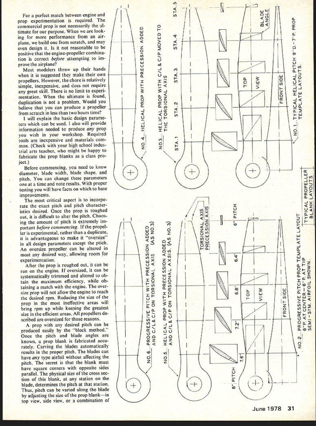
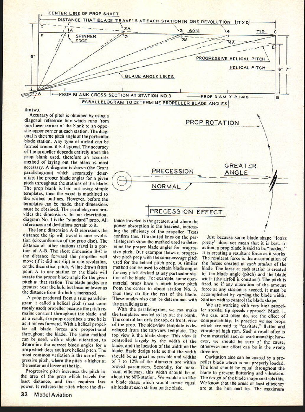
Accuracy of pitch is obtained by using a diagonal reference line which runs from one lower corner of the blank to an opposite upper corner at each station. The diagonal is the true pitch angle at the particular blade station. Any type of airfoil can be formed around this diagonal. The accuracy of the propeller depends entirely upon the prop blank used, therefore an accurate method of laying out the blank is most necessary. A diagram is shown (the Grant parallelogram) which accurately determines the proper blade angles for a given pitch throughout the stations of the blade. The prop blank is laid out using simple templates, then the wood is machined to the scribed outlines. However, before the templates can be made, their dimensions must be obtained. The parallelogram provides the dimensions. In our description, diagram No. 1 is the "standard" prop. All references and deviations pertain to it.
The long dimension A-B represents the distance the tip will travel in one revolution (circumference of the prop disc). The distance at all other stations travel is a portion of A-B. The short dimension B-C is the distance forward the propeller will move (if it did not slip) in one revolution, or the theoretical pitch. A line drawn from point A to any station on the blade will create the proper blade angle for the given pitch at that station. The blade angles are greatest near the hub, but become lower as the distance from the hub is increased.
A prop produced from a true parallelogram is called a helical pitch (most commonly used) propeller because the pitch remains constant throughout the blade, and as a result, the prop describes a true helix as it moves forward. With a helical propeller all blade forces are proportional throughout the blade. The same method can be used, with a slight alteration, to determine the correct blade angles for a prop which does not have helical pitch. The most common variation is the use of progressive pitch, where the pitch is higher at the center and lower at the tip.
Progressive pitch increases the pitch in the area of the prop which travels the least distance, and thus requires less power. It reduces the pitch where the distance traveled is the greatest and where the power absorption is the heaviest, increasing the efficiency of the propeller. Tests confirm this. The dotted lines on the parallelogram show the method used to determine the proper blade angles for progressive pitch. Our example shows a progressive pitch prop with the same average pitch used for the helical pitch prop. A similar method can be used to obtain blade angles for any pitch desired at any particular station of the blade. For example, some commercial props have a much lower pitch from the center to about station No. 3, than they do for the rest of the blade. These angles can also be determined with the parallelogram.
With the parallelogram, we can make the templates needed to lay out the blank. The control factor is the top, or front, view of the prop. The side-view template is developed from the top-view template. The top view is the blade shape. This view is controlled largely by the width of the blade, and the location of the width on the blade. Basic design tells us that the width should be as great as possible and widths of 7 to 12% of the diameter are within proved parameters. Secondly, for maximum efficiency, this width should be at about the 60% station. We would also like a blade shape which would create equal air loads at each station on the blade.
Just because some blade shape "looks pretty" does not mean that it is best. In action, a prop blade is said to be "loaded." It is creating a resultant force as it works. The resultant force is the accumulation of the forces created at each station of the blade. The force at each station is created by the blade angle (pitch) and the blade width (the airfoil is constant). The pitch is fixed, so if any alteration of the amount of force at any station is needed, it must be accomplished by varying the blade width. Station widths control the blade shape.
We are working with very high propeller speeds; tip speeds approach Mach 1. We can, and often do, see the effect of compressibility. In practice we see props which are said to "cavitate," flutter and vibrate at high rpm. Such a result often is from material and/or workmanship; however, we should be sure of the cause, otherwise our effort can be in the wrong direction.
Cavitation also can be caused by a propeller blade which is not properly loaded. The load should be equal throughout the blade to prevent fluttering and vibration. The design of the blade shape controls this. We know that the areas of least efficiency are at the hub and tip. The maximum blade width is fixed at the 60% station. Fortunately, if we use practical dimensions for the hub and tip, and connect them with smooth flowing lines to the maximum width, we arrive at a usable shape. If we should discover cavitation during tests, altering the blade shape at suspect stations may very well equalize the blade load and be the cure needed.
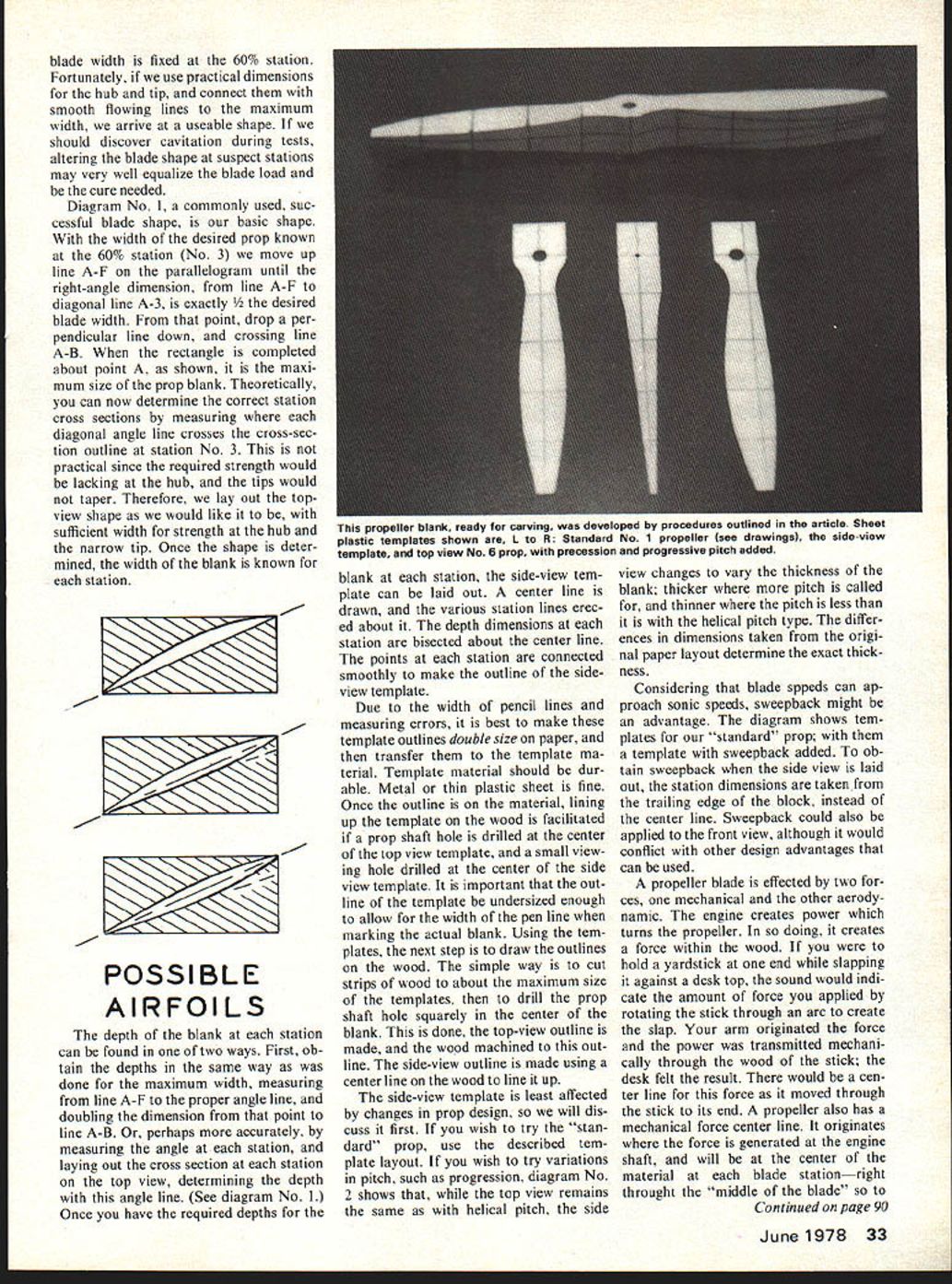
Diagram No. 1, a commonly used, successful blade shape, is our basic shape. With the width of the desired prop known at the 60% station (No. 3) we move up line A-F on the parallelogram until the right-angle dimension, from line A-F to diagonal line A-3, is exactly 1/2 the desired blade width. From that point, drop a perpendicular line down, and crossing line A-B. When the rectangle is completed about point A, as shown, it is the maximum size of the prop blank. Theoretically, you can now determine the correct station cross sections by measuring where each diagonal angle line crosses the cross-section outline at station No. 3. This is not practical since the required strength would be lacking at the hub, and the tips would not taper. Therefore, we lay out the top-view shape as we would like it to be, with sufficient width for strength at the hub and the narrow tip. Once the shape is determined, the width of the blank is known for each station.
POSSIBLE AIRFOILS
The depth of the blank at each station can be found in one of two ways. First, obtain the depths in the same way as was done for the maximum width, measuring from line A-F to the proper angle line, and doubling the dimension from that point to line A-B. Or, perhaps more accurately, by measuring the angle at each station, and laying out the cross section at each station on the top view, determining the depth with this angle line. (See diagram No. 1.) Once you have the required depths for the blank at each station, the side-view template can be laid out. A center line is drawn, and the various station lines erected about it. The depth dimensions at each station are bisected about the center line. The points at each station are connected smoothly to make the outline of the side-view template.
Due to the width of pencil lines and measuring errors, it is best to make these template outlines double size on paper, and then transfer them to the template material. Template material should be durable. Metal or thin plastic sheet is fine. Once the outline is on the material, lining up the template on the wood is facilitated if a prop shaft hole is drilled at the center of the top view template, and a small viewing hole drilled at the center of the side view template. It is important that the outline of the template be undersized enough to allow for the width of the pencil line when marking the actual blank. Using the templates, the next step is to draw the outlines on the wood. The simple way is to cut strips of wood to about the maximum size of the templates, then to drill the prop shaft hole squarely in the center of the blank. This is done, the top-view outline is made, and the wood machined to this outline. The side-view outline is made using a center line on the wood to line it up.
The side-view template is least affected by changes in prop design, so we will discuss it first. If you wish to try the "standard" prop, use the described template layout. If you wish to try variations in pitch, such as progression, diagram No. 2 shows that, while the top view remains the same as with helical pitch, the side view changes to vary the thickness of the blank: thicker where more pitch is called for, and thinner where the pitch is less than it is with the helical pitch type. The differences in dimensions taken from the original paper layout determine the exact thickness.
Considering that blade speeds can approach sonic speeds, sweepback might be an advantage. The diagram shows templates for our "standard" prop, with the template with sweepback added. To obtain sweepback when the side view is laid out, the station dimensions are taken from the trailing edge of the block, instead of the center line. Sweepback could also be applied to the front view, although it would conflict with other design advantages that can be used.
A propeller blade is affected by two forces, one mechanical and the other aerodynamic. The engine creates power which turns the propeller. In so doing, it creates a force within the wood. If you were to hold a yardstick at one end while slapping it against a desk top, the sound would indicate the amount of force you applied by rotating the stick through an arc to create the slap. Your arm originated the force and the power was transmitted mechanically through the wood of the stick; the desk felt the result. There would be a center line for this force as it moved through the stick to its end. A propeller also has a mechanical force center line. It originates where the force is generated at the engine shaft, and will be at the center of the material at each blade station—right through the "middle of the blade" so to speak. This is a force applied to the propeller.
As the propeller works it creates thrust. This force is transmitted to the aircraft through the blade material via the engine shaft. The thrust would also have a center line of force. Thrust is a result of a combination of lift developed from the airfoil upper curve and the "fan effect" of the bottom of the blade. They would not be in line, so the resultant is between them. So, there is a resultant line of thrust which
could be parallel with the mechanical line of thrust, from tip to hub. Ideally, the two lines of thrust would be in the same location chord-wise. If they are not, there is a torsional rotational force set up which would tend to rotate the blade about the mechanical line of force.
We can make variations to the "standard" design in the top view of the blade which can approach the ideal position for the lines of force. In diagram No. 3 we show how the thrust line of force can be lined up with the mechanical line of force to remove any tendency for the blade to change pitch while working. This would be advantageous when especially thin blades are used.
Another design consideration is precession, not to be confused with the "precession force" created through the gyroscopic action of a prop in rotation. Precession is simply moving ahead the point where the thrust would normally be applied by the blade in the propeller arc. With normal blade shapes the center line of thrust coincides with the line that passes through the center of the engine shaft, looking from the front of the shaft, top view of the propeller blade. This is the center line of rotation. The blade angles are created with it as their center. As the blade moves through the arc of rotation this is considered to be the line along which thrust is generated. Pitch is also measured from this line. If the center line of thrust can be moved ahead of the center line of rotation, the effective angle of the blade to the arc of rotation will be increased without changing the physical angle.
The advantage of precession is an increase in pitch without adding drag. Drag is created by the physical angle of the blades; with precession you do not change the physical angle. This effective change in pitch can be used to advantage. If your aircraft requires 7° of pitch at terminal velocity, with precession the prop pitch can be only 6¾" as an example; you will still have an effective pitch of 7°. The lower drag of the 6¾" physical pitch is a plus factor. The combined lower drag will allow more engine rpm and power.
The only drawback is that precession moves the center line of thrust away from the line of mechanical force. A torsional rotation force is created. It is possible that with rigid blades, the torsional rotation force could be disregarded, taking advantage of the precession instead. The "standard" prop shape, with precession added, is shown in diagram No. 4. Diagrams No. 5 and 6 show how all these design factors can be incorporated into the blade shape.
Before finalizing the ideas you may wish to try with your custom made props, the type of blade airfoil should be considered. The considerations for a blade airfoil are the same as those for a wing. You wish the greatest lift possible, with the least amount of drag — the old L/D ratio again. Secondly, the air speed should be considered. For a Formula I propeller, for instance, the average blade air speed is about 350 mph, with the tip speed approaching the sonic range. An airfoil developed for those speed ranges would be most efficient. Many modern airfoils have an excellent lift-drag ratio, with far less drag than older styles. If the amount of drag is reduced without serious loss of lift, the result is the same as adding horsepower.
In Part II we will show how you can transform all these ideas into actual props, in your own workshop. Additionally, we will explain how to test and tailor them to your particular needs.
Transcribed from original scans by AI. Minor OCR errors may remain.

