
How to Trim a Model
Part I
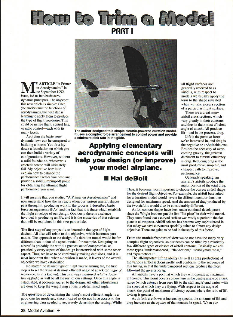
My article "A Primer on Aerodynamics," in the September 1992 issue, led us into basic aerodynamic principles. The object of this new article is simple: once you understand the functions of aerodynamics, the next step is learning to apply them to produce the type of flight you desire. This could be in free flight, control line, or radio control—each with its many facets.
Applying the basic aerodynamic laws can be compared to building a house: you first lay down a foundation on which you can then build a variety of configurations. However, without a solid foundation, whatever is erected thereon will ultimately fail. My objective here is to explain how to balance the performance factors you need and provide a solid jumping-off point for obtaining the ultimate flight performance you want.
I will assume that you studied "A Primer on Aerodynamics" and now understand how the air reacts when our various aircraft shapes pass through it, producing work in the process. I described basic force arrangements (FAs) and the fact that it is these which establish the flight envelope of our design. Obviously there is a science involved in producing an FA, and it is the mysteries of that science that will be explained in this two-part article.
The first step of any project is to determine the type of flight desired. All else will relate to this objective, which becomes paramount. The approach to the design of a duration model would be far different than to that of a speed model, for example. Designing an aircraft is probably the world's greatest act of compromise, as practically every aspect of the design is intertwined with some other aspect. Thus, we have to continually make decisions, and it is most important that, when a decision is made, it favors the overall objective we have established.
Establishing the wing incidence
No matter the desired type of flight you're aiming for, the first step is to set the wing at its most efficient angle of attack (or angle of incidence, as it is often called). This is always measured relative to the line of flight, as will be all the rest of our settings. Once this angle is established, it becomes sacred to the design. All other adjustments are done to keep the wing flying at this predetermined angle.
The question of determining the wing's most efficient angle is a good one for modelers, since most of us do not have access to the engineering data needed to accurately determine the setting. While all flight surfaces are generally referred to as airfoils, with respect to models we usually apply the term to the shape revealed when we take a cross section of a particular flight surface.
There are a great many airfoil cross sections, which vary greatly in their contours and thus in their most efficient angle of attack. All produce lift—and in the process, drag.
Lift is the positive force we're interested in, and drag is the negative or undesirable one. Besides the necessity of overcoming gravity, the greatest detriment to aircraft efficiency is drag. Reducing drag is the most productive, simplest, and cheapest path to improved performance.
Generally speaking, an aircraft's airfoils produce the major portion of the total drag. Thus, it becomes most important to choose the correct airfoil shape for the desired flight objective. For example, the airfoil best suited for a duration model would have a far different contour than one designed for maximum speed. And the amount of drag produced by the two airfoils would also be considerably different.
Airfoil development and categories
Airfoil contour shapes have been under continual development since the Wright brothers put the first "flat plate" in their wind tunnel. They soon found that a curved surface was vastly superior to the flat plate in all respects. Airfoil science has become very sophisticated; today we have curvatures precisely suited to almost any design objective. There are gains to be had in the study of this factor.
From the modeler's point of view we do not have too many very complex flight objectives, so our needs can be filled by a relatively few different types or classes of airfoil contours. Basically we call these types:
- Undercambered
- Flat-bottom
- Semisymmetrical
- Symmetrical
The all-important lifting ability (as well as drag production) of the various airfoil sections pretty well conforms to the sequence of this listing, in that the undercambered sections produce the most lift—and the greatest drag.
All airfoils have a point at which they will operate at maximum efficiency. Their most efficient point occurs somewhere in the usable angle-of-attack range (which extends from zero lift to the stall angle) and varies with the speed at which they are flying. With respect to the angle of attack, the point of maximum efficiency occurs where the ratio of lift to drag is greatest.
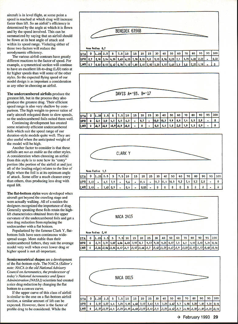
As airfoils are flown at increasing speeds, the amounts of lift and drag increase with the square of the increase in speed. At some point in level flight a speed is reached where drag will increase faster than lift. So an airfoil's efficiency is determined by the angle at which it is flown and the speed involved. This can be summarized by saying an airfoil should be flown at its best angle of attack within its speed range. Violating either of these two factors will reduce aerodynamic efficiency. Various airfoil contours have greatly different reactions to the factor of speed. For example, a symmetrical section will continue to have an excellent lift-to-drag (L/D) ratio at far higher speeds than will some of the other styles. So the expected flying speed of our model design is as important a consideration as any other in choosing an airfoil.
Undercambered sections
The undercambered airfoils produce the greatest lift, but in the process they also produce the greatest drag. Their efficient speed range is also very shallow by comparison. The high weight-to-power ratios of early aircraft relegated them to slow speeds, so the undercambered foils suited them well.
Continuing development has created some relatively efficient undercambered foils which suit the speed range of our duration-style models quite well. They are also useful when the anticipated weight of the model will be high.
Another factor to consider is that these airfoils are not as stable as the other styles. A consideration when choosing an airfoil from this style is to note how its "entry" portion (the portion of the airfoil at and just aft of the leading edge) relates to the line of flight when the foil is at its optimum angle of attack. Some offer a much cleaner entry than others, thus producing less drag with equal lift.
Flat-bottom sections
The flat-bottom styles were developed when aircraft got beyond the crawling stage and were actually walking. Designers recognized the importance of drag. Generally speaking these foils retain the high-lift characteristics obtained from the upper curvature of the undercambered foils and get a nice drag reduction from replacing the undercamber with a flat bottom.
Popularized by the famous Clark Y, flat-bottom foils have seen continuous widespread usage. More stable than their undercambered fathers, they suit the average model very well when even lower drag or higher speed is not all-important.
Semisymmetrical sections
Semisymmetrical shapes are a development of the flat-bottom style. The NACA (the National Advisory Committee for Aeronautics, predecessor of NASA) scientists created a nice drag reduction by changing the flat bottom to a convex curve.
If the upper curve of this class of airfoil is similar to the one on a flat-bottom airfoil section, a similar amount of lift can be expected. However, there is the factor of profile drag to be considered. While the foil's upper curvature remains the same as on the flat-bottom airfoil, the added convex curve on the bottom increases the overall profile area of the section, which will result in an increase in drag.
Usually a compromise is struck in the design of one of these airfoils: the upper curve is reduced (lowered) to compensate for the addition to the bottom. At a given speed, lift would be less on such an airfoil than on one with a flat bottom; however, the reduced drag of the convex-bottom section would enable an increase in flying speed, which in turn would result in an easy restoration of the lost lift.
So, using the convex-bottom airfoil can produce as much lift as the flat-bottom section, along with an increase in flying speed. With modeling, especially control line and radio control, semisymmetrical airfoil sections have proven very useful and are widely employed except for specialized purposes.
Symmetrical sections
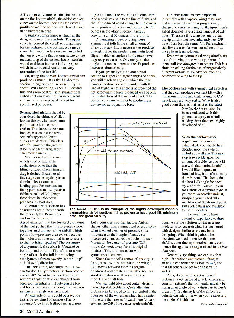
Symmetrical airfoils should be considered the ultimate of all, at least in theory, when maximum performance is the consideration. The shape, as the name implies, is such that the airfoil section's upper and lower curves are identical. This class of airfoil provides the greatest stability and least drag, and it can produce useful lift.
Symmetrical sections are widely used on aircraft in applications other than lifting surfaces when minimum drag is desired. Examples of this usage can be anything from door handles to skis and landing gear. For such streamlining purposes, at low speeds a thickness ratio of about 3:1 (length three times the thickness) produces the least drag.
A symmetrical section has characteristics different from the other styles. In "A Primer on Aerodynamics" I explained that the forward curvature of the foil pushes the air molecules closer together, and that aft of the airfoil's high point a low-pressure area exists because the molecules have not had time to return to their original spacing. The curvature of a symmetrical section is identical on both top and bottom. Therefore, at a zero angle of attack the foil is producing aerodynamic forces equally in both directions ("up" and "down").
This being true, one might ask: how can a symmetrical section produce useful lift? What happens is that as the section's angle of attack is changed from zero, a differential in lift between the top and bottom is created favoring the direction in which the angle was increased.
An example: a section might develop 100 ounces of aerodynamic force in both directions at a zero angle of attack. The net lift is, of course, zero. Add a positive angle to the line of flight, and the lift produced could change to 125 ounces in the positive direction and decrease to 75 ounces in the other direction, thereby providing a net 50 ounces of useful lift.
An amazing aspect of using these symmetrical foils is the small amount of angle of attack necessary to produce enough lift for the model to maintain level flight. Incidence angles of only one to two degrees prove ample. Obviously, as the angle of attack is increased the lift produced increases dramatically.
If you gradually tilt a symmetrical section to higher and higher angles of attack, you will reach an angle at which the rear lower curvature becomes parallel with the line of flight. As this angle is approached the net aerodynamic force produced will be only in the direction of the angle of attack. The bottom curvature will not be producing a downward aerodynamic force.
Center of pressure and stability
Airfoil shapes, other than symmetrical ones, display what is called center-of-pressure (C/P) movement as their angle of attack (or incidence) changes. As the angle of attack increases, the center of pressure moves forward, away from its original position. This does not occur with symmetrical sections.
Since the model's center of gravity is fixed, it is obvious that when the wing's C/P moves forward from its original position it will create an unstable (or less stable) condition with respect to the model's pitch attitude.
We have heard of certain designs having tail problems. Quite often this problem can be traced to using an airfoil in the outer part of the wingspan which has a center of pressure that moves forward more (or sooner) than the C/P of the center-section airfoil.
For this reason it is most important (especially with a tapered wing) to be sure that as the airfoil section is progressively changed toward the wing tip, the tip-section's airfoil does not have a greater amount of C/P travel. To assure this, wing designers often use tip airfoils that have inherently less C/P travel than the center foil. For maximum stability the use of a symmetrical section at the tip is an ideal solution.
Even when symmetrical wing airfoils are used from wing tip to wing tip, some still show less abrupt behavior than others. This is a situation calling for the use of progressively different airfoils as we advance from the center of the wing to the tip.
The bottom line with symmetrical airfoils is that they can produce excellent lift with a minimum of drag and that, having no C/P travel, they are very stable. What is also good about them is that most of the latest NACA/NASA research has been conducted with this general category of airfoils, making them the most highly developed of all.
Choosing the incidence
With the performance objectives for your craft established, you should have decided upon the style of airfoil you will use. The next step is to decide upon the amount of incidence you will use with that particular airfoil. I would like to quote an ironclad law, but unfortunately there is none. The fact is that the best L/D angle for each style of airfoil varies—even for airfoils of a similar style. If you were an aerodynamicist, studying your airfoil data would reveal the desired point. But such data is not available to most modelers.
However, we do have extensive experience to draw upon. A simple solution for the average modeler is to research what has been used with designs similar to the one he is designing. When thinking about the decision, realize that most airfoils, other than symmetrical ones, commence lifting at some angle of incidence less than zero.
Generally speaking, high-lift sections commence lifting at an angle of incidence as low as −4°, and all others are between that value and 0°.
Thus, if you were to set a high-lift section at a +3° angle of attack (which is a common setting), the foil would actually be flying at an angle of +7° relative to its angle of zero lift. So the style of the airfoil is a definite consideration when you're selecting the angle of incidence.
I'll break off the discussion at this point, as the remainder is fairly lengthy. Save this portion for continuity and reference when you study the concluding part.
Part Two will cover the process of developing force arrangements for your model and how to get the ultimate flight performance from them. I'll also talk about trimming methods. To be continued.
Hal DeBolt
Transcribed from original scans by AI. Minor OCR errors may remain.

