
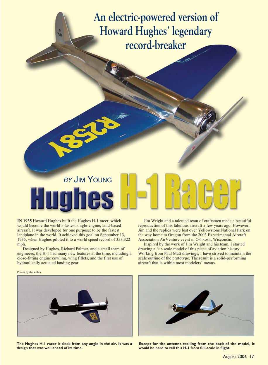
Hughes H-1 Racer
An electric-powered version of Howard Hughes' legendary record-breaker
BY JIM YOUNG
IN 1935 Howard Hughes built the Hughes H-1 racer, which would become the world’s fastest single-engine, land-based aircraft. It was developed for one purpose: to be the fastest landplane in the world. It achieved this goal on September 13, 1935, when Hughes piloted it to a world speed record of 353.322 mph.
Designed by Hughes, Richard Palmer, and a small team of engineers, the H-1 had many new features at the time, including a close-fitting engine cowling, wing fillets, and the first use of hydraulically actuated landing gear.
Jim Wright and a talented team of craftsmen made a beautiful reproduction of this fabulous aircraft a few years ago. However, Jim and the replica were lost over Yellowstone National Park on the way home to Oregon from the 2003 Experimental Aircraft Association AirVenture event in Oshkosh, Wisconsin.
Inspired by the work of Jim Wright and his team, I started drawing a 1/12-scale model of this piece of aviation history. Working from Paul Matt drawings, I have strived to maintain the scale outline of the prototype. The result is a solid-performing aircraft that is within most modelers’ means.
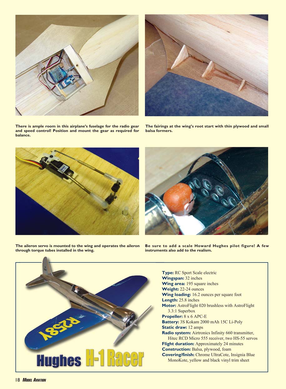
There is ample room in this airplane’s fuselage for the radio gear and speed control. Position and mount the gear as required for balance. The fairings at the wing’s root start with thin plywood and small balsa formers. The aileron servo is mounted to the wing and operates the aileron through torque tubes installed in the wing. Be sure to add a scale Howard Hughes pilot figure. A few instruments also add to the realism.
Specifications
- Type: RC Sport Scale electric
- Wingspan: 32 inches
- Wing area: 195 square inches
- Weight: 22–24 ounces
- Wing loading: 16.2 ounces per square foot
- Length: 25.8 inches
- Motor: AstroFlight 020 brushless with AstroFlight 3.3:1 Superbox
- Propeller: 8 x 6 APC-E
- Battery: 3S Kokam 2000 mAh 15C Li-Poly
- Static draw: 12 amps
- Radio system: Airtronics Infinity 660 transmitter, Hitec RCD Micro 555 receiver, two HS-55 servos
- Flight duration: Approximately 24 minutes
- Construction: Balsa, plywood, foam
- Covering/finish: Chrome UltraCote, Insignia Blue MonoKote, yellow and black vinyl trim sheet
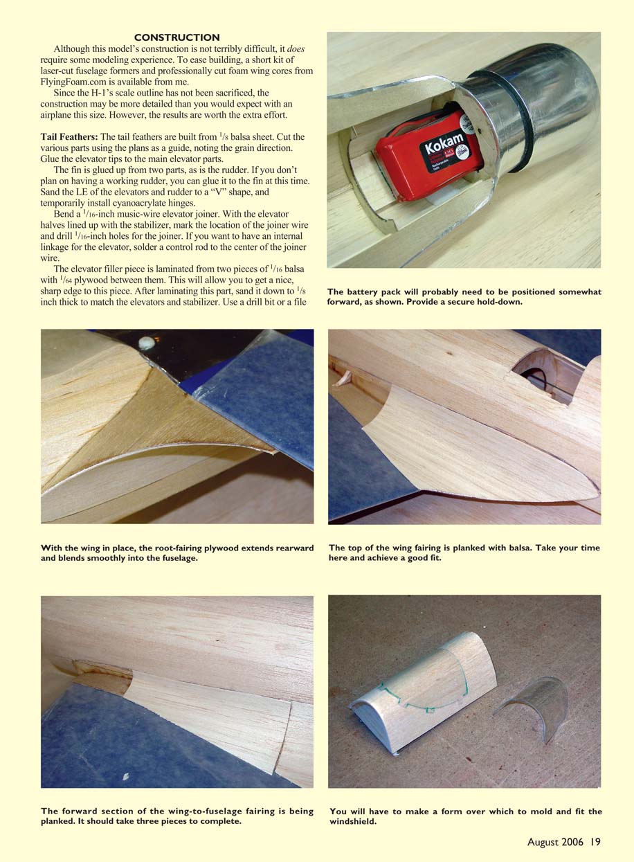
With the wing in place, the root-fairing plywood extends rearward and blends smoothly into the fuselage. The top of the wing fairing is planked with balsa. Take your time here and achieve a good fit. The battery pack will probably need to be positioned somewhat forward, as shown. Provide a secure hold-down. The forward section of the wing-to-fuselage fairing is being planked. It should take three pieces to complete. You will have to make a form over which to mold and fit the windshield.
Construction
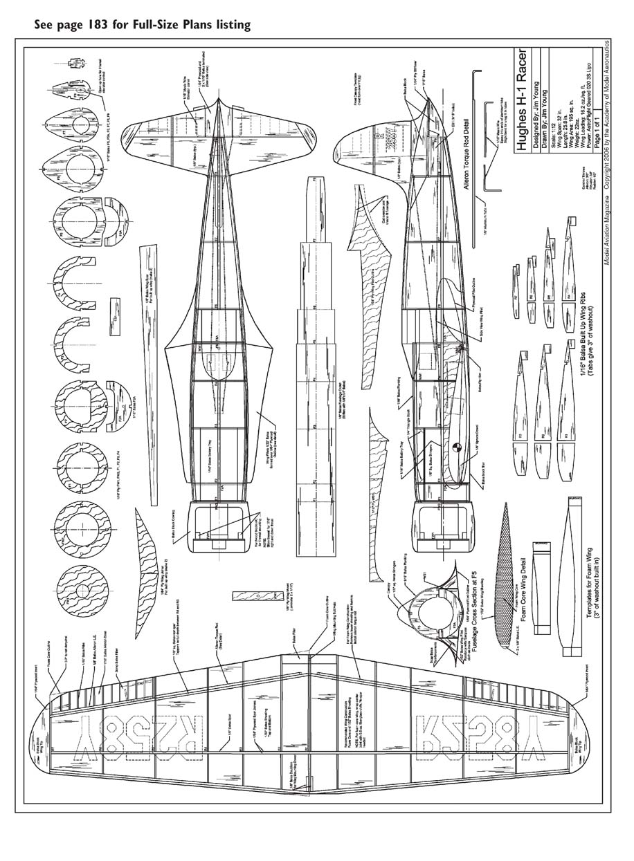
Although this model’s construction is not terribly difficult, it does require some modeling experience. To ease building, a short kit of laser-cut fuselage formers and professionally cut foam wing cores from FlyingFoam.com is available from me. Since the H-1’s scale outline has not been sacrificed, the construction may be more detailed than you would expect with an airplane this size. However, the results are worth the extra effort.
Tail Feathers
The tail feathers are built from 1/8-inch balsa sheet. Cut the various parts using the plans as a guide, noting the grain direction. Glue the elevator tips to the main elevator parts. The fin is glued up from two parts, as is the rudder. If you don’t plan on having a working rudder, you can glue it to the fin at this time. Sand the leading edges of the elevators and rudder to a “V” shape, and temporarily install cyanoacrylate hinges. Bend a 1/16-inch music-wire elevator joiner. With the elevator halves lined up with the stabilizer, mark the holes and drill through the stabilizer and elevator to accept the wire. Fit the elevator and glue the joiner in place.
The elevator filler piece is laminated from two pieces of 1/16-inch balsa with 1/64-inch plywood between them. This will allow you to get a nice, sharp edge to this piece. After laminating this part, sand it down to 1/8-inch thick to match the elevators and stabilizer. Use a drill bit or a file to finish the shape, and make a groove in the front edge to clear the elevator joiner.
Wing
You can build the wing with a foam core or with traditional built-up construction. All the prototypes have the foam wing. The airfoil is the same NACA 23012/06 as was used on the original H-1. The tip airfoil has been thickened from 6% to 8% to improve the stall performance.
Start the foam-wing construction by cutting the cores using the templates on the plans. A total of 3° of washout is built into the templates.
Prepare the wing sheeting from 1/32-inch balsa. Use your favorite method for sheeting foam. I use epoxy and vacuum-bagged it with my wife's FoodSaver.
Trim the sheeting to the cores and mark the location of the ailerons. Glue the 1/4-inch balsa leading-edge in place and carve and sand it to shape. Cut a piece of 1/2-inch balsa to the outline of the wingtip.
Using a razor saw, cut a slit in the trailing edge of this piece as shown on the plans. Cut a piece of 1/64-inch plywood and wedge it into this slit. Secure it with thin cyanoacrylate and trim it to match the wingtip block. The 1/64-inch plywood will reinforce the balsa and make for a tough trailing edge.
Glue the wingtip to the wing, making sure to line up the 1/64 plywood with the trailing edge. Carve and sand the tip block to shape. Remove the sheeting from the aileron area. Face the aileron opening with 1/8-inch balsa at the trailing edge of the wing and 1/16-inch balsa on the inboard end. Repeat this process for the other wing.
Frame up the ailerons. Cut two aileron bases from 1/16-inch balsa and mark the locations of the ribs on them. Cut a piece of 1/8-inch balsa oversize for the leading edge and glue it in place. Hold the aileron up to the opening in the wing, mark the height of the leading edge, and trim it to size. Cut oversize triangle ribs from scrap 1/16-inch balsa and glue them in place. Using a sanding block, sand the ribs to match the leading edge and taper the trailing edge to match the wing TE. Add scrap balsa to reinforce the torque-rod location. Sand the leading edge to a "V" shape.
Mark the aileron and wing for cyanoacrylate hinges, and temporarily install the hinges. With this size model I cut down the hinges to roughly 1/4 inch wide so the control movement is not too stiff.
The aileron torque rods are made from 1/8-inch aluminum tube with 1/16-inch music wire exposed into the ends. Cut the aluminum tubes to size per the plans. Cut and bend the 1/16-inch music wire to size.
The portion of the music wire that is epoxied into the tube has a slight bend in it so that it does not rattle around in the tube. Do not make this bend too large or you will deform the tube. Rough up the music wire and clean it and the tubes with alcohol. Epoxy the music wire into the tubes, making sure to make a right and a left torque rod.
Mark the location of the torque rods on the bottom of the wing. Remove a 1/8-inch-wide strip of the bottom wing sheeting. Dig out the foam and trial-fit the torque rod in place. When you are satisfied with the fit, mark and drill a 1/16-inch hole in the leading edge of the aileron and fit it to the torque rod. Apply a thin coat of petroleum jelly to the torque rod and place it in the channel.
Cut a piece of 1/8-inch balsa oversize and glue it in place over the torque rod. Make sure you don't affect the shape of the airfoil. Once the glue has set, trim and sand the 1/8-inch balsa flush with the wing sheeting.
Sand the root of each wing panel to achieve the proper dihedral as noted on the plans. Tack-glue the two wing panels together.
The center wing joint is reinforced with 0.5- or 0.75-ounce fiberglass cloth, top and bottom. If you cut the cloth on the 45° bias, you will get a stronger joint since all the fibers, instead of just half of them, will cross the joint.
Fuselage
The fuselage is built on a removable crutch. Cut the crutch from 1/8-inch balsa and add scrap 1/4-inch balsa as a stiffener. Prepare the fuselage formers by laminating F2A to F2 and F5A to F5. Trace the outline of the upper portion of F6 onto two pieces of scrap 1/16-inch balsa. These will be used to make a fixture for forming the canopy later.
Mark the WS1s with the former locations and score each one at the rear of F5. Thread formers F1–F7 onto the crutch with the stiffener up. F8 is pinned to the rear of the crutch.
Glue the WS1s and WM1 in place. Make sure to keep the formers square to the crutch and avoid gluing the formers to the crutch.
Add the 1/8-square balsa side stringers to the fuselage assembly. Leave the stringers long at F1 to key into FW2, and make them long enough to reach F9. Make sure the formers are square to the crutch before making the stringers permanent.
Glue the ES1s to F8 and the side stringers. Glue F9 in place and add two 1/8-square balsa stringers on top of the ES1s between F8 and F9. Use care here to keep everything square.
Glue the bottom stringer to F9. At this point make sure that you haven't made the crutch a permanent part of the fuselage.
The entire fuselage is covered with 1/16-inch balsa. There are very few flat spots on this model, so it must be planked with thin strips of balsa. If you are new to planking, you can use 3/32-inch balsa instead. This will give you a little more "meat" to shape if the strips don't line up perfectly. Following is the planking sequence I used.
I cut two 1/16-inch balsa strips approximately 1 inch wide. These are glued in place on each side of the fuselage starting at the side stringers. At the tail these strips will span from the side stringers to the stabilizer mount. Once these pieces are in place, put the wing in position and square it to the fuselage. Temporarily pin the wing in position.
Drill a 1/8-inch hole through F2 into the wing leading edge. Glue a piece of 1/8-inch dowel into the wing. With the wing lined up to the fuselage, drill a hole through the wing and into WM1. Open the hole in the wing to clear a 6-32 bolt, and tap WM1 for 6-32 threads. Toughen the threads with thin cyanoacrylate and retap.
Fit the stabilizer to the fuselage, and sand the mounting area to square it to the wing and fuselage. When you are satisfied with the alignment, glue it in place.
Add the fin assembly and the top 1/8-square balsa stringers. Add the elevator filler piece in place to the bottom of the fin and use it to capture the elevator joiner wire.
Now the fun starts. Cut a bunch of 1/4-inch-wide strips of 1/16-inch balsa. If you cut them with a slight bevel on each side, they will fit better on the curved fuselage. Continuing from the first strips, plank each side, applying the pieces first to one side and then to the other.
I used aliphatic glue along the edge of each plank and positioned it on the fuselage. Then, while holding the plank firmly against the previous plank, I applied thin cyanoacrylate to the inside of the plank at each former.
Try to keep the rows even, and trim and sand the width of the planks at the ends to avoid having to bend the planks too much. Once the top of the fuselage is finished, you can remove the crutch.
Install the elevator and rudder linkage. Plank the lower rear portion of the fuselage. These planks are glued to F5A. Plank the lower front portion of the fuselage between F1 and F2A.
When sanding the planking, start with 80-grit sandpaper and a sanding block. You need to use this grit of sandpaper to cut down all the bumps and level the planking. If you use finer sandpaper, you will just polish the bumps and still have an uneven surface. Use a light touch when sanding and be careful around each of the formers.
Cut and install the battery tray between F1 and F3. Some balsa triangle stock at each of the formers adds some gluing surface.
Carve the cowling from balsa block. This is best done with a lathe or a drill press, but can be done by hand. Glue FW2 to the rear of the block, and use it and the outlines from the plans to guide your progress.
Glue the cowling in place to the front of F1. FW1 is set into the front of the cowling and should have 1/16 inch of downthrust and right thrust. Add four hardwood mounting blocks to allow for FW1 to be screwed in place. FW1 is set up for an AstroFlight brushless 020 motor with a Superbox.
Carve balsa block for the lower tail section and glue it in place. Carve balsa block for each side of the fin. This model does have a short nose moment, so taking time to hollow out these blocks will help with balancing. Use filler to blend the tail pieces together, and shape into a sharp point.
The wing fillets are not as difficult as they look. A good portion of the fillets on the original H-1 were made with flat sheet aluminum, so they can easily be duplicated with balsa sheeting.
Cut the 1/64-inch plywood fillet outline. Protect the wing with plastic wrap or waxed paper and screw it to the fuselage. Slide the fillet outline into place and trim it to fit the fuselage. Study the side view of the plans to see how the fillet outline curves up the side of the fuselage.
When you are satisfied with the fit, glue the fillet outline in place. Add scrap balsa triangles between WS1 and the fillet outline to keep it firmly against the wing.
Transfer the side-view fillet outline from the plans to the side of the fuselage. Cut an oversize piece of 1/32-inch balsa to match the side-view fillet outline and to span from F4 to the end of the fillet.
Hold the sheeting in place against the side of the fuselage and carefully press it down to the fillet outline. You should be able to form it to match the fillet outline. The sheeting should lay flat against the side of the fuselage and the top of the wing.
Once you are satisfied with how this should fit, cut a piece of 0.5-ounce fiberglass cloth to the size of the sheeting. Lay the cloth on the inside of the sheeting and squeegee on some epoxy. Press the sheeting in place and pin it down. Add scrap balsa to support the leading edge of the fillet and to give something for the next piece of sheeting to glue to.
Repeat this process for the next piece of sheeting, which spans from F4 to midway between F2 and F3. Finish the forward portion of the fillets with some small balsa blocks.
The canopy is fabricated from two pieces of sheet acetate formed over a simple fixture. Remember the two pieces of scrap balsa with the outline of F6 on them? Cut them out and glue some 1/16-inch balsa sheeting over them to make a fixture that is approximately 2 inches long. Sand the balsa smooth and wipe it down to remove any dust.
Cut two rectangular pieces of acetate oversize for the canopy. The acetate should fit the fixture so that the lower edges can be fully taped down. With a piece of acetate securely taped down over the fixtures, gently warm it with a heat gun. There will be a fine line between softening and shrinking the acetate. I went through a couple pieces before I got the technique down.
You will need two pieces of acetate that will hold their form when removed from the fixture, one of which is cut to a rectangular shape and is trimmed to fit between F5 and F6. When you are pleased with the fit, tape it in place and cut the forward windshield using the template on the plans. The tabs on this part will be inserted into slots cut in the fuselage.
Fit the windshield up against the canopy and trim it to fit. When you are satisfied with the fit, mark the locations of the tabs and cut slots in the fuselage planking for them. The canopy is installed after finishing, and a piece of trim tape seals the seam between the two pieces.
Final Assembly
Cut an opening in the top of the wing for the aileron servo and install the linkage. The elevator and rudder servos are installed between F4 and F5. Make sure they do not interfere with the aileron linkage.
I covered my H-1 with Insignia Blue MonoKote on the wing and Chrome UltraCote on the fuselage. I used a straightedge to scribe panel lines and a dressmaker’s wheel to add rivet detail. The call numbers for the wing were cut from yellow trim sheet, and the tail numbers were cut from black trim sheet.
I found a 1/12-scale radial engine online, but it was too small for the cowl. I cut off the jugs and used a ping-pong ball to make a new crankcase. I printed out a dashboard with gauges from my home PC and painted a 1/12-scale Williams Bros. pilot to finish the cockpit.
I am flying my H-1 with an AstroFlight 020 motor with a Superbox (3.3:1), a Castle Creations Thunderbird-18 ESC, a Kokam 2000 mAh 15C Li-Poly battery pack, and an APC 8 x 6E propeller. This power system will give close to 20 minutes of flight time and really hauls the H-1 around.
Flying
The H-1 requires a simple hand launch to get it going. I have launched it by grabbing the rear edge of the cowl or behind the wing and using the fillets for support. The AstroFlight 020 has plenty of power for climbout, so the model is forgiving of a weak launch. The prototype required quite a bit of down-trim, and the plans have been updated with some positive incidence built into the stabilizer mount.
Once in the air, the H-1 is a pleasure to fly. It is fairly fast, but it can be slowed for more leisurely flying. It is basically a point-it-where-you-want-it-to-go kind of airplane. It does require a bit of down-elevator while inverted, but not an excessive amount.
The 3° of washout in the wing tames the stall characteristics. There is no sign of high-speed stalls, and you really have to slow it down for the low-speed stall. If the propeller is turning, it is hard to stall.
With that in mind, it is wise to keep on a bit of power for landings until you are over the field. Then just flare it gently to keep the nose up and the propeller out of the dirt.
I hope you enjoy flying your little piece of history.
Jim Young [email protected] MA
Transcribed from original scans by AI. Minor OCR errors may remain.

