
Hummin'bird
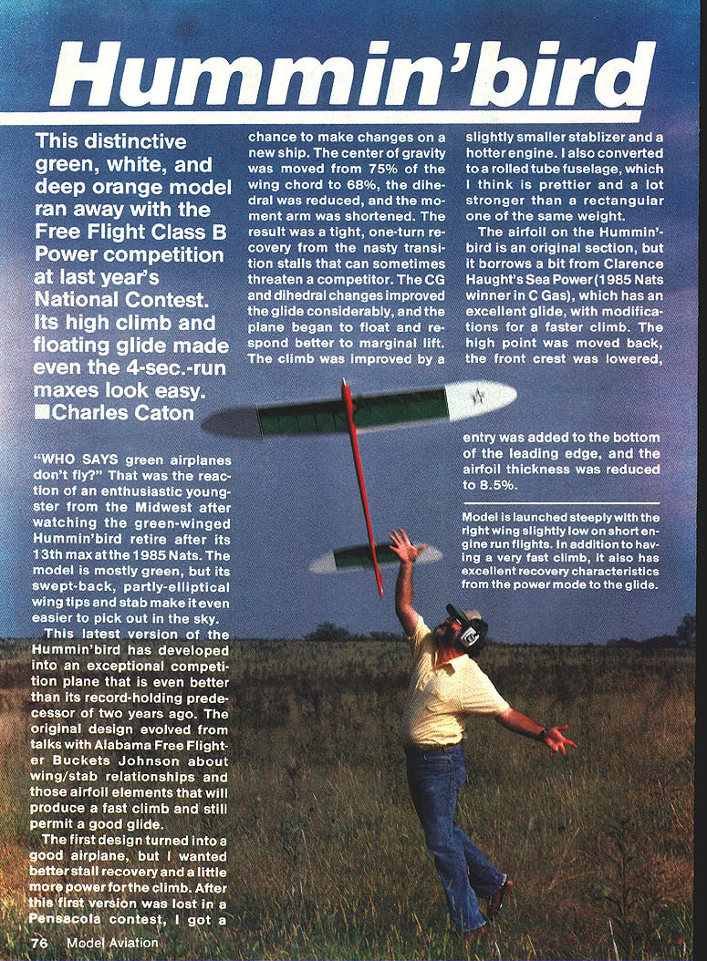
This distinctive green, white, and deep-orange model won the Free Flight Class B Power competition at last year’s National Contest. Its high climb and floating glide made even the 4-second run maxes look easy.
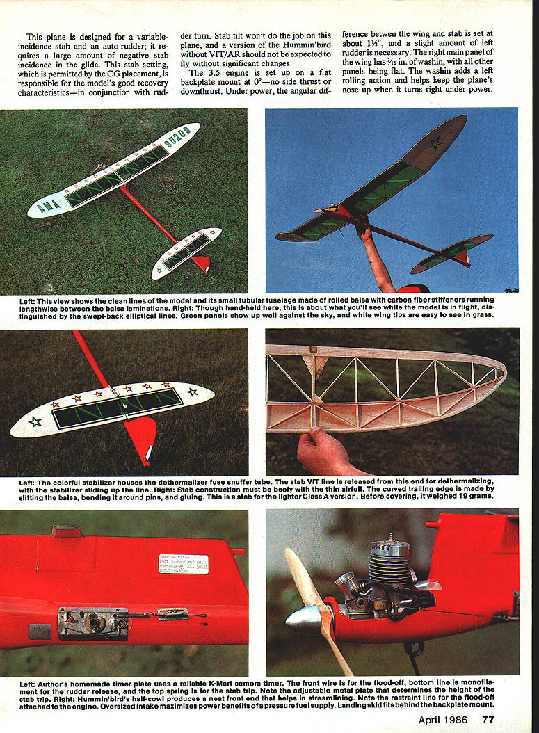
"WHO SAYS green airplanes don't fly?" was the reaction of an enthusiastic youngster after watching the green-winged Hummin'bird retire after its 13th max at the 1985 Nats. The model is mostly green, but its swept-back, partly-elliptical wingtips and stab make it easy to pick out in the sky.
Design evolution
This latest Hummin'bird has developed into an exceptional competition plane, even better than its record-holding predecessor. The original design evolved from discussions about wing/stab relationships and airfoil elements that produce a fast climb while permitting a good glide.
After the first design was lost at a contest, changes were made on a new ship: the CG was moved from about 75% of the wing chord to 68%, dihedral was reduced, and the moment arm was shortened. The result was a tight, one-turn recovery from transition stalls. These CG and dihedral changes improved the glide and made the plane float and respond better to marginal lift. Climb was improved by a slightly smaller stabilizer and a hotter engine. The fuselage was converted to a rolled-tube form, which is both prettier and stronger than a rectangular fuselage of the same weight.
Airfoil and flight characteristics
The Hummin'bird uses an original airfoil section that borrows some ideas from Clarence Haught's Sea Power (1985 Nats C Gas winner). Modifications were made for a faster climb: the high point was moved back, the front crest was lowered, entry was added to the bottom of the leading edge, and thickness was reduced to about 8.5%.
The model is launched steeply with the right wing slightly low on short engine-run flights. It has a very fast climb and excellent recovery from power to glide. The plane is designed for a variable-incidence stab and an auto-rudder (VIT/AR); it requires a large amount of negative stab incidence in the glide. This setting, permitted by the CG placement, is responsible for the model's good recovery characteristics in conjunction with rudder turn. Stab tilt alone won't do the job; a Hummin'bird without VIT/AR will require significant changes to fly well.
The engine is set on a flat backplate mount at 0°—no side thrust or downthrust. Under power, the angular difference between wing and stab is about 1½°, and a slight amount of left rudder is needed. The right main panel of the wing has 3/16 in. of washin; all other panels are flat. The washin adds a left rolling action and helps keep the nose up when the plane turns right under power.
Hummin'bird is designed for Cat. III flying: fast climb is essential. It has a good power pattern, will hold longer engine runs, and its fine glide will give many other designs a hard time in other categories.
Fuselage
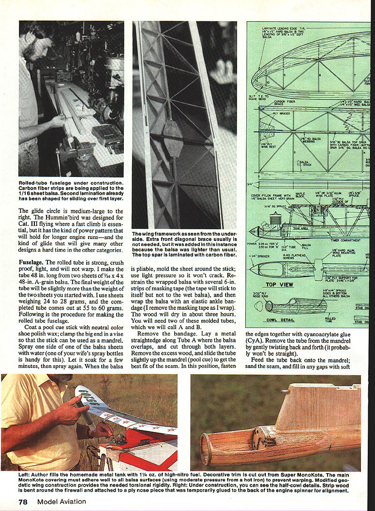
The rolled-tube fuselage is strong, crush-proof, light, and will not warp. Make the tube 48 in. long from two sheets of 1/16 x 4 x 48-in. A-grain balsa. Typical starting sheets weigh 24–28 grams each; completed tube weight is about 55–60 grams.
Rolled-tube construction (sequence)
- Coat a pool-cue stick (mandrel) with neutral-color shoe polish or wax and clamp the big end in a vise.
- Spray one side of a balsa sheet with water (a spray bottle is handy). Let soak a few minutes and spray again until pliable.
- Mold the sheet around the mandrel using light pressure; it will not crack if flexible.
- Restrain the wrapped balsa with several 6-in. strips of masking tape (the tape will stick to itself but not to wet balsa). Wrap the balsa with an elastic ankle bandage; remove the masking tape as you wrap. Let dry (about three hours).
- Repeat to make two molded tubes, called Tube A and Tube B.
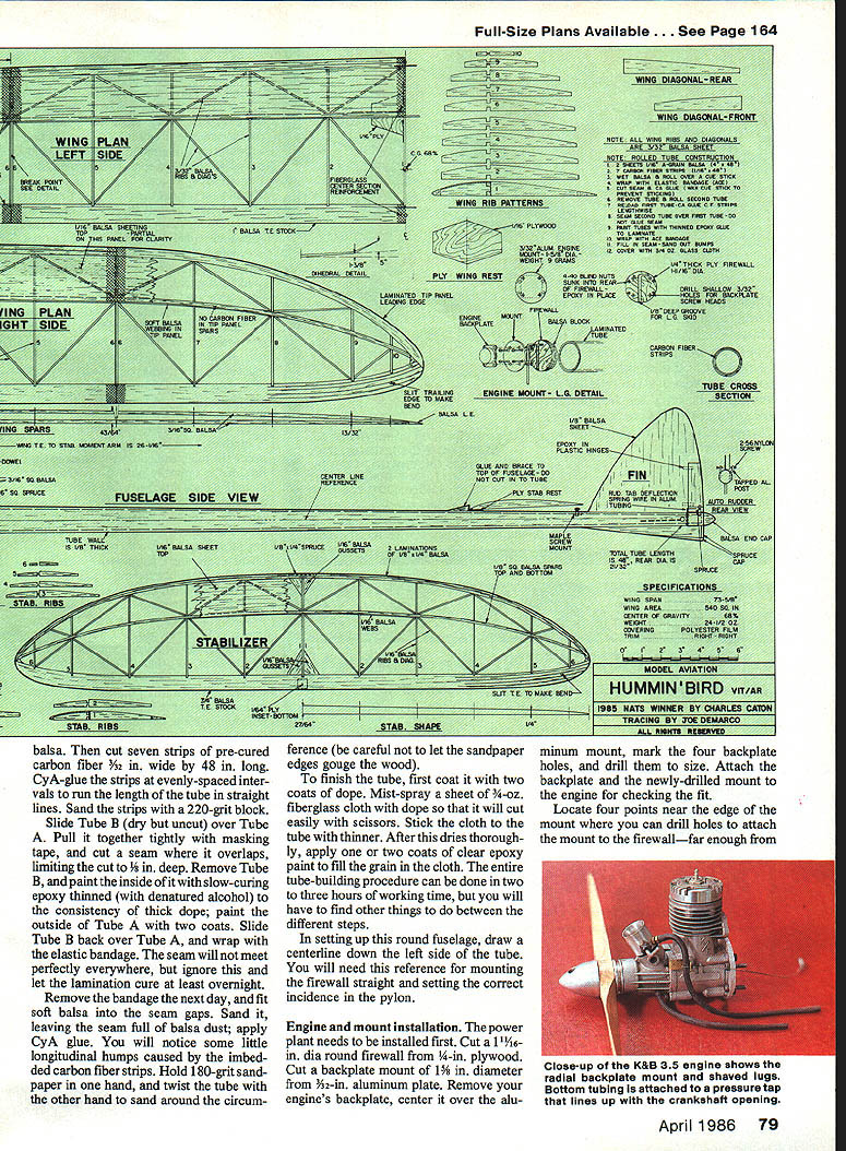
- Remove the bandage. Lay a metal straightedge along Tube A where the balsa overlaps and cut through both layers. Remove excess wood and slide the tube slightly on the mandrel to get the best-fit seam position. Fasten the seam edges together with CyA (cyanoacrylate) glue.
- Gently remove Tube A from the mandrel by twisting back and forth. Feed it back onto the mandrel, sand the seam, and fill gaps with soft balsa filler.
- Cut seven strips of 1/16-in. balsa and seven strips of pre-cured carbon-fiber, 3/32 in. wide and 48 in. long. CyA-glue the strips at evenly spaced intervals running the length of the tube to create longitudinal stiffeners. Sand the strips with a 220-grit block.
- Slide Tube B (dry but uncut) over Tube A, pull tightly with masking tape, and cut a seam where it overlaps (limit cut to 1/8 in. deep). Remove Tube B.
- Paint the inside of Tube B with slow-curing epoxy thinned with denatured alcohol to the consistency of thick dope. Paint the outside of Tube A with two coats. Slide Tube B back over Tube A and wrap with the elastic bandage. Let the lamination cure at least overnight.
- Remove the bandage the next day and fit soft balsa into seam gaps. Sand until the seam is full of balsa dust, then apply CyA glue.
- Counter small longitudinal bumps from embedded carbon-fiber strips by holding 180-grit sandpaper in one hand and twisting the tube in the other to sand around the circumference (be careful not to gouge).
- Finish the tube: coat with two coats of dope. Mist-spray a sheet of 3/4-oz. fiberglass cloth with dope, stick it to the tube with thinner, and after drying apply one or two coats of clear epoxy paint to fill the grain in the cloth.
- Draw a centerline on the left side of the tube for firewall and pylon alignment.
Allow curing times between steps; total working time is a few hours but overall process spans a day or two.
Engine and mount installation
- Cut a 1-1/16-in.-dia. round firewall from 1/4-in. plywood.
- Cut a backplate mount from 3/32-in. aluminum plate. Remove the engine backplate, center it over the aluminum plate, mark the four backplate holes, and drill them to size. Attach the backplate and newly-drilled mount to the engine to check fit.
- Locate four mounting points near the edge of the mount (far enough from the center for good screw purchase but not too near the edge). Drill and fasten the mount to the firewall. Reattach the engine to the mount.
- Position the engine so the heads of the hex screws will clear the engine case (this puts screw heads near the edge of the mount). Remove the mount, drill the marked holes for 4-40 hex bolts, align the mount over the firewall, drill through the firewall using the mount as a guide, and install 4-40 blind-keeper nuts behind the firewall. (Put a little Vaseline in the nut threads to ease later removal.) Drill shallow pockets in the firewall for engine backplate bolt heads as required.
- Consider fuel-tank provisions now. A round metal tank of about 1 1/4 oz capacity with a pressure line at the front-top and two rear-bottom lines (feed and flood-off) is one option. If using a pen bladder or pacifier tank, build a fuel-proof compartment in the tube, seal wood with epoxy glue, and cover with clear epoxy paint to resist high-nitro fuel.
- Cut a 3/8-in.-thick hard-balsa block to fit snugly inside the tube and epoxy it to the rear of the firewall. With the engine and mounting plate attached to the firewall (and a straightedge mounted in place of a prop), align the engine with the fuselage centerline and epoxy-glue the firewall into the tube with the engine still attached.
- If using a beam mount instead of a backplate mount, the front end will be less crowded but about 20 grams heavier. Converting to a beam mount requires shifting the pylon forward about 5/16 in. and the tail surfaces forward the same amount to maintain moments.
- Bend a skid with an L on top and sink it into the firewall; it is held in place by the mount and resists twisting.
Pylon
- Build the pylon over the plans. The four main supports are spruce and run to the bottom of the tube.
- Use an aluminum wing plate (beveled on underside edges) for improved streamlining. Fasten the wing plate to the pylon with two 4-40 flat-head screws countersunk into the aluminum and anchored into blind nuts or a small threaded aluminum bar inside the pylon.
- Pylon sheeting is 1/8-in. medium balsa. Add two small 1/32 ply doublers outside the sheeting under the aluminum wing plate for support.
- The top of the pylon has small plywood lugs front and back to accept holes for blind wing keys.
- Make the pylon longer than the wing chord so the wing can find its natural resting place when tied down with rubber bands; it should be keyed in that position.
When fitting the pylon into the tube:
- Use a straightedge to set and mark the top centerline for alignment.
- Cut the hole for the pylon, leaving the tank compartment area intact and fitting the tank walls to the top of the tube as required.
- Set proper pylon incidence: measure from the top rear of the pylon to the side centerline of the tube; this measurement must be equal on both sides. Epoxy the pylon in place and bead-glue along seams. Check wing incidence with a straightedge along the bottom of the wing and adjust before glue fully cures.
Half-cowl
- Select an aluminum spinner backplate of the desired size. Make a round plywood nose piece from 3/32-in. ply slightly larger than the spinner backplate and cut a hole for the engine shaft.
- Tack-glue a 1/32-in. spacer to the spinner backplate. Glue the plywood nose piece to the spacer and mount the engine with prop to set final clearance.
- Note the firewall is larger than the wrap—wrap the tube with 1/8-in. balsa fill extending about 2 in. back and beveled at the rear.
- Cut three 1/8 x 1/8 spruce stringers, about 6 in. long. Run one strip from the nose piece down the centerline on the left side of the tube, CyA-gluing in spots and applying slow-curing epoxy around the firewall and stress points. Repeat right side and bottom to outline the cowl.
- Press soft balsa into gaps and hold with CyA. Apply slow epoxy at critical points, close remaining cracks with filler, and sand to final shape so the front faired to spinner size and the rear faired into the tube.
- Leave clearance to access engine mounting bolts—maintain a small access space between engine and cowl while building the stringers.
Wing
The wing is a beefy modified-geodetic structure with front sheeting to withstand a hot climb. The top spar at the wing’s high point is medium-hard 3/32-in. sq. balsa with pre-cured carbon fiber glued to top and bottom for rigidity.
- Ribs: cut from 4- to 6-lb. 3/32-in. sheet balsa. If wood is heavy, step down to 1/16-in. sheet for tip ribs.
- Leading-edge sheeting (from LE to over the high-point spar): target 11–13 grams per 3 x 36-in. sheet.
Construction sequence:
- Notch the trailing edge and pin it over the plans. Laminate the leading edge and pin it down. Pin the bottom spar in place.
- Use a 1/16-in. sq. wood piece to ensure rib notch depth, then set ribs over the bottom spar. Adjust rib lengths at leading and trailing edges if necessary.
- CyA-glue ribs in place and add the top spar. End ribs on each wing panel can be slanted to match dihedral breaks—cut templates to the angle to establish correct dihedral during build.
- Add webbing but leave center clear for a plywood brace to be added when joining halves.
- Fit and glue rear diagonals, leaving front diagonals off temporarily.
- Mark and cut 1/16-in. leading-edge sheeting. Tack-glue the sheet at the front and back of each rib, then remove the wing from the plans to ensure the sheeting is straight before final gluing to avoid a washboard effect. Continue CyA-gluing sheeting to ribs.
- With the wing upside down, cut and trim front diagonals to conform to the sheeting contour.
- Build wing tips similarly, making tip ribs shorter and fitting tip sheeting to contour.
- Join panels with a plywood brace, align, and reinforce join with glass or tape as required.
Final strengthening:
- Join tips to main panels with 5-minute epoxy, then check dihedral. If adjustment needed, heat epoxy with covering iron to soften and reposition.
- Cover front joint back to the spar with 3-oz. glass cloth and clear epoxy paint. Do same on top and bottom of trailing edge. Apply two coats of dope to area first to help adherence.
- Double the cloth weight at the wing center section after inserting a carbon-fiber brace in the leading and trailing edges.
- Cut out and countersink the plywood wing support into the bottom of the wing structure. Add a main ply dihedral brace and 1/8-in. plywood braces around the center rib and spars; use epoxy for this assembly.
Sanding and shaping:
- Rough-trim leading edge and refine shape with a coarse sandpaper block. Use a large sanding block (about 4 x 9 in.) to bring diagonals and sheeting into alignment with ribs. Start with 220-grit and finish with 400-grit.
Stabilizer
- Stab construction is similar to the wing but must be very light. Use thin airfoil sections and a curved trailing edge formed by slitting balsa and bending around pins, gluing as you go.
- Aim for an uncovered finished stab weight under 1 oz (about 28 g). Use 9–11 g sheet wood for ribs and top sheeting if possible.
- If stab comes out heavy, cover with a lighter polyester film to reduce tail weight by up to 10 grams.
Final assembly and finishing
- Temporarily mount rudder, stab mount, engine, prop, pylon, wing, and stab and hold with rubber bands.
- Place masking tape over the wing center and mark 68% of chord. Hang the model by the rubber bands at this point and shift the pylon slightly to fine-tune CG—slide the stab with the pylon to keep the same moment relationship. Set the CG about 2–3% ahead of 68% (the paint and finishing usually shift it aft slightly).
- Glue the pylon (with epoxy), stab mount, and vertical fin in place.
- Cover fin, pylon, and half-cowl with 3-oz. glass cloth: stick cloth with dope and thinner, then apply one or two coats of clear epoxy paint.
- Mix dope and talcum powder to a fairly thick consistency and apply two or three filler coats, sanding with 220-grit then finishing with 320–400-grit.
- Spray fuselage with epoxy color paint to resist high-motor fuels.
VIT/AR and trim notes:
- There are several reliable V/T arrangements; whatever system is chosen, it must be adjusted carefully and thoroughly tested. Any suspect or changed part must be tested repeatedly.
- If you want a faster plane with independent power and glide trim, VIT/AR is recommended.
Test flying
- Ensure the engine runs reliably and that the flood-off system and VIT operate correctly before flying.
- Check wing incidence and trim. Hand-glide tests should show a slight left turn in the power setting and enough negative stab incidence to prevent diving.
- Use an instant DT with a short delay for testing if desired. Set the wing at 2% to 3% wash and launch high with the right wing slightly low.
- Trim with the competition prop and run the engine at peak RPM; trimming with slow props or a rich engine requires re-trimming for speed.
- Remember that the plane needs quite a bit of additional negative stab incidence for the glide—about 1/4 in. on the stab in the author’s example. The rudder should drop to the right for the glide.
If you decide to build a Hummin'bird, put some green on it somewhere—and help prove that green airplanes do fly.
Full-size plans available. See page 164.
Transcribed from original scans by AI. Minor OCR errors may remain.

