
Symmetry is a life pursuit; does it matter with an airplane?
Dean Pappas | [email protected]
Also included in this column:
- What engine placement does to your airplane
- That troublesome horizontal tornado
- A revolutionary power option for CL electric fliers
If it flies, it probably has a propeller in front of it. Propellers turn horsepower into thrust, and they also stir the air up. It’s the price we pay.
I’m going to write about symmetry. Forget airplanes for a second; let’s discuss it in the general sense. We humans are bilaterally symmetric; that is, barring industrial accidents, we look the same on the left as on the right. This generally works out well, because if one leg were shorter than the other, we would run around in circles.
Still, you can be sure that the wildebeest in the herd with shorter legs on the left side will be the first one the lions eat. On top of that, I don’t know of any birds that have unequal-length wings, so symmetry must be good for flight.
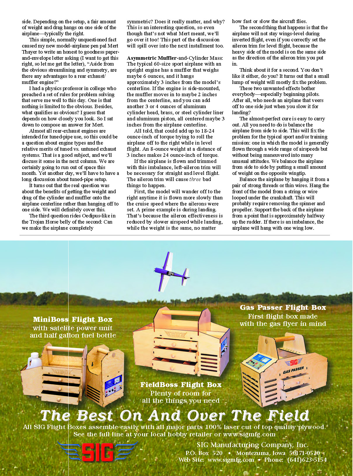
Yet our airplanes are far from symmetric, even if everything lines up when you fold the building plans down the middle and hold them up to the light. For one thing, the propeller spins one way, and that creates a spiral-airflow tornado along the entire length of the airplane. Even a fairly simple analysis of the interaction of that horizontal tornado with the rest of the airframe gets involved quickly. (That won’t stop us!)
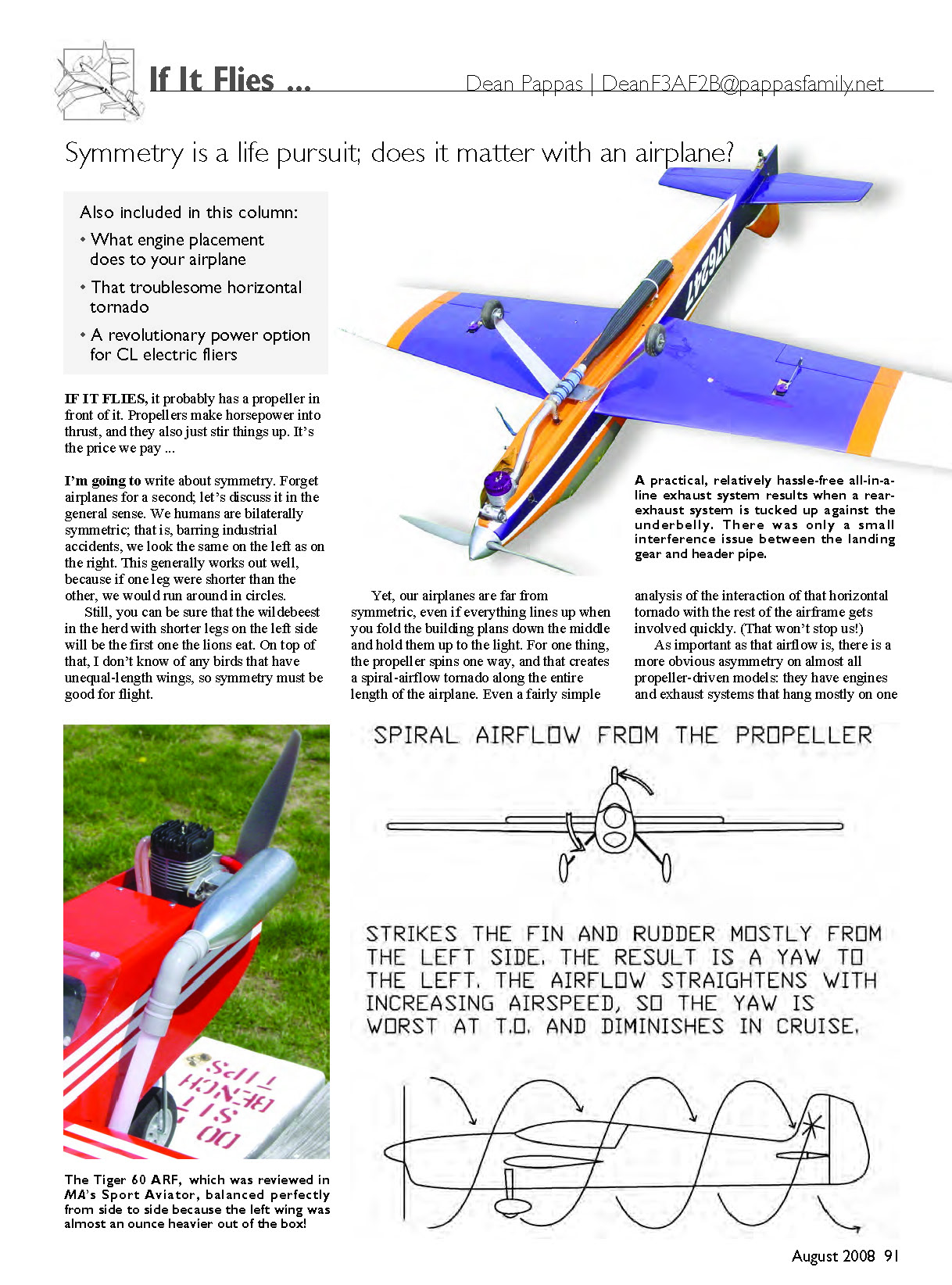
As important as that airflow is, there is a more obvious asymmetry on almost all propeller-driven models: they have engines and exhaust systems that hang mostly on one side. Depending on the setup, a fair amount of weight and drag hangs on one side of the airplane—typically the right. This simple, normally unquestioned fact caused my new model-airplane pen pal Mert Thayer to write an honest-to-god paper-and-envelope letter asking, “Aside from the obvious streamlining and symmetry, are there any advantages to a rear exhaust/muffler engine?”
I had a physics professor in college who preached a set of rules for problem solving that serve me well to this day. One is that nothing is limited to the obvious. Besides, what qualifies as obvious? I guess that depends on how closely you look. So I sat down to compose an answer for Mert. Almost all rear-exhaust engines are intended for tuned-pipe use, so this could be a question about engine types and the relative merits of tuned vs. untuned exhaust systems. That is a good subject, and we’ll discuss it some in the next column. We are certainly going to run out of space this month. Yet another day, we’ll have to have a long discussion about tuned-pipe setup.
It turns out the real question was about the benefits of getting the weight and drag of the cylinder and muffler onto the airplane centerline rather than hanging off to one side. We will definitely cover this.
The third question rides Oedipus-like in the Trojan Horse belly of the second: can we make the airplane completely symmetric? Does it really matter, and why? This is an interesting question, so even though that’s not what Mert meant, we’ll go over it too! This part of the discussion will spill over into the next installment.
Asymmetric muffler-and-cylinder mass
The typical 60-size sport airplane with an upright engine has a muffler that weighs maybe 6 ounces and hangs approximately 3 inches from the model’s centerline. If the engine is side-mounted, the muffler may be closer (around 2 inches), but the cylinder, head and associated hardware can add another 3–4 ounces centered roughly 3 inches from the centerline.
All told, that could add up to 18–24 ounce-inches of torque trying to roll the airplane off to the right while in level flight. For example, an 8-ounce weight at a distance of 3 inches produces 24 ounce-inches of torque.
If the airplane is flown and trimmed with this imbalance, left-aileron trim will be necessary for straight-and-level flight. The aileron trim will cause three bad things to happen:
- The model will wander off to the right anytime it is flown more slowly than the cruise speed at which the ailerons were set. A prime example is during landing. Aileron effectiveness is reduced at slower airspeeds while the weight remains the same, so the imbalance becomes more influential at low speed.
- The airplane will not stay wings-level during inverted flight, even if you correctly set the aileron trim for level upright flight, because the heavy side of the model is on the same side as the direction of the aileron trim you put in.
- A remaining side-to-side imbalance in rotational inertia causes a wingtip with added mass to drop slightly whenever the G loading changes, such as at the beginning of a loop. The side with more rotational inertia will "hang out" of the loop until the higher-G portion of the maneuver is established. Once the loop is underway the balance returns, but you’ll see a small roll every time the G loading changes. This inertial imbalance annoys anybody trying to fly loops precisely but is not a big deal for most sport fliers.
These first two unwanted effects bother everybody—especially beginning pilots. After all, who needs an airplane that veers off to one side just when you slow it for landing?
The almost-perfect cure is easy to carry out: balance the airplane from side to side. This will fix the problem for a typical sport or training mission, where the model is generally flown through a wide range of airspeeds without being maneuvered into many unusual attitudes. Balance the airplane by putting a small amount of weight on the opposite wingtip.
How to balance:
- Hang the model from a pair of strong threads or thin wires.
- Hang the front of the model from a string or wire looped under the crankshaft (you will probably need to remove spinner and prop).
- Support the back of the airplane from a point approximately halfway up the rudder.
- If there is an imbalance the airplane will hang with one wing low; add sticky-backed lead weights or finishing nails to the light wingtip until it hangs level.
This is difficult to do in any wind, so do it in the workshop before your next flying session.
Now that you have balanced the model, the aileron trim should be able to return to center. This simple balancing act works well but is less than perfect because of the rotational-inertia effect described above.
If you really want to understand that third effect, look up "moment of inertia" and "center of percussion" (try Wikipedia). You’ll also learn about what gives a baseball bat its sweet spot.
Spiral airflow — that troublesome horizontal tornado
The spiral airflow that swirls along the model's length destroys any hope of having a truly symmetric airplane. Jet pilots (pure jet and ducted fan) know this and enjoy the benefits of straight, symmetric airflow.
As soon as it starts turning, the spiral airflow of a normal "right-hand" propeller strikes the right side of whatever "chin" the airplane has and the left side of the fin and rudder. The center of the fin and rudder area is normally centered above the aircraft's thrust line, so the net action is that the tail is pushed to the right and the nose is pushed to the left. That's why your airplane yaws left on takeoff and often requires right thrust to compensate.
There are other effects as well: pure torque reaction, the rolling effect of spiral airflow on the wings and stabilizer, and the tough-to-explain but generally unimportant P-factor.
The preceding explanation is the reason why the model needs right thrust. I will attempt to justify that statement in the next installment.
News flash
When I was a kid, the aeromodeling press actually disseminated news. In this age of the Internet forum and irrefutable anonymous authority, a magazine such as MA rarely gets a "scoop." The following might be an exception.
The Bob Hunt/Dean Pappas skunkworks has been busy since, following Mike Palko's lead, switching to electric propulsion for our CL Aerobatics (Stunt) efforts. After refining the power plant enough to convince ourselves that electric power was already at parity with "wet" power, we turned some of our attention to airframe design.
What design changes would suit electric power best? Torque and all the unwanted trim effects because of propeller rotation have been a pain for Stunt fliers around the world.
The first idea was to adopt a torque-sharing contra-rotating gearbox, as is sold in Europe for electric-powered RC Aerobatics by my pen pal Michael Rammel of Germany. The gearbox sounded like it might be too heavy, so we came up with the idea of a counter-rotating twin. Bob has the airframe roughly half done, and the drawings look snazzy. Both of these schemes would allow a Stunt aircraft to trim out better.
Then Kaz Minato sent word, through mutual friend Frank McMillan, to Bob about an interesting experiment he had just tried. Kaz is the many-time Japanese National CL Stunt champion, a member of the Japanese national team, and an all-around nice guy.
Remember what I wrote at the beginning of this column about how what we call obvious depends on how carefully you look? Kaz looked carefully and did the obvious, and smart, thing. Reversing the running direction is easy with brushless motors, so he reversed his motor rotation, put a pusher propeller of the same size and pitch on the airplane, and flew it. The result was astonishing.
Remember that with a normal right-hand propeller, the spiral airflow yaws an airplane to the left? The spiral airflow and yaw tendency both get worse when the airspeed drops. In CL the speed drops anytime you fly toward the top of the hemisphere.
Using a left-hand (pusher) propeller now causes the airplane to subtly yaw to the right as it slows, and this reduces the loss of line tension when flying in the upper half of the hemisphere. It's obvious.
We duplicated Kaz's tests, swapping the APC 12x6E prop for a 12x6EP (pusher), and started test-flying. Sure enough, line tension improved everywhere, but even more at the top of the circle. Bob has even started flying with slightly slower lap times, achieving a more pleasantly paced presentation. Poor line tension usually forces us to keep up the speed to maintain good control at the top of the circle.
Flying in calm conditions has improved too. Now, when flying through his or her own turbulence in nearly calm conditions, the airplane rolls out and away from the pilot instead of into the circle, as usually happens. Remember: you saw it here first!
That's it for now. I'm going flying, how about you? Have fun, and do take care.
MA
Transcribed from original scans by AI. Minor OCR errors may remain.

