
Your model's stability hangs on its neutral point
Dean Pappas | [email protected]
IN THE LAST column, I waxed nostalgic about an airplane I had “designed” and built as a teenager. The word “designed” is in quotes, because at least one of the airplane’s critical features was borrowed, or I could call it copied—all right, stolen! It was the stabilator pivot point’s design and placement.
A stabilator is an all-moving horizontal tail, rather than one with a separate movable surface at the trailing edge (TE). Piper Cherokees and all supersonic fighter jets have them. I had been warned that stabilator design was tricky and that they had a habit of overloading elevator servos, causing a crash—or that they tended to flutter off the airplane altogether. The solution, for me then, was to copy a proven design.
Many moons ago, as an engineering student, you would have thought I would have had plenty of reading to do for my course work. But being the airplane geek that I am (still), after much reading of calculus-laden textbooks and a few nonmathematical books written for aeromodelers, I learned that the secret of successful stabilator design lay in proper counterbalancing and the placement of the pivot at the flying surface’s aerodynamic center (AC).
Let’s leave the counterbalancing issue aside right now. I’ll write about flutter another time, and it will be important then.
Why place the pivot at the stabilator’s AC?
Why does the pivot have to be placed at the stabilator’s AC? If the stabilator airfoil is symmetric, or even a flat plate, the torque around the AC (or pivot point) is zero. It stays constant at zero throughout almost the entire range of useful control-surface deflections.
That means that a servo could provide the necessary control, no matter how fast the airplane were flying. That’s a big deal. When your model is in a dive and accelerating earthward, the last thing you want is an elevator control that gets harder and harder to move, especially when up-elevator seems like such a good idea.
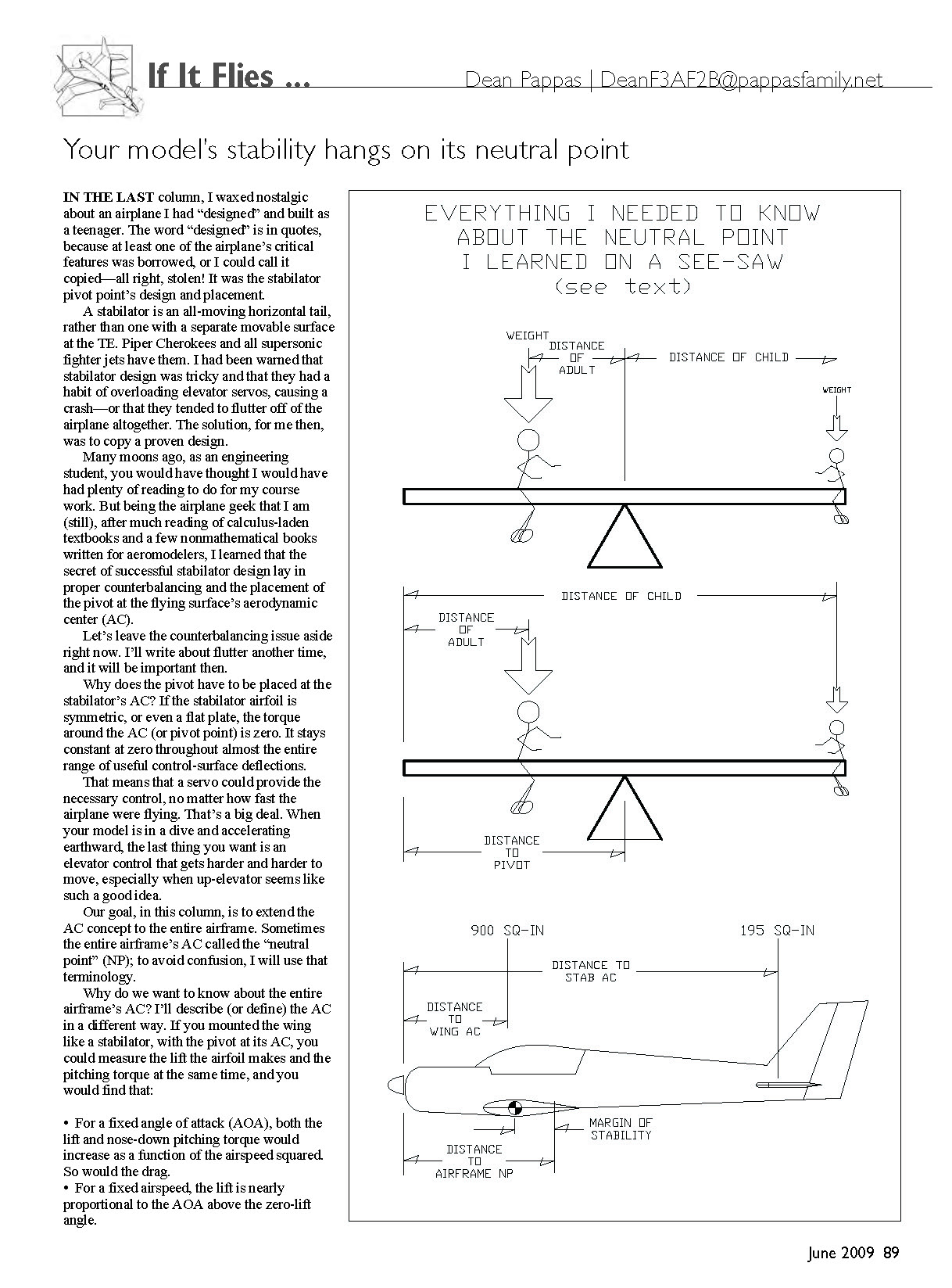
Our goal, in this column, is to extend the AC concept to the entire airframe. Sometimes the entire airframe’s AC is called the “neutral point” (NP); to avoid confusion, I will use that terminology.
Extending the AC concept to the entire airplane
Why do we want to know about the entire airframe’s AC? I’ll describe (or define) the AC in a different way. If you mounted the wing like a stabilator, with the pivot at its AC, you could measure the lift the airfoil makes and the pitching torque at the same time, and you would find that:
- For a fixed angle of attack (AOA), both the lift and nose-down pitching torque would increase as a function of the airspeed squared. So would the drag.
- For a fixed airspeed, the lift is nearly proportional to the AOA above the zero-lift angle.
- For a fixed airspeed, the nose-down pitching torque is nearly constant at every AOA, except in or near stall. For symmetric and flat-plate airfoils, this nose-down torque equals zero and increases with airfoil camber.
The fact that it is possible to pick a point on the wing where you can imagine the lift as acting through that point, and that the nose-down torque does not change as the AOA and lift change, means that you can analyze what happens as the airplane’s nose rises and falls. And as long as the aircraft’s airspeed does not change much, only the lift that is provided by the wing and horizontal tail change. That simplifies the analysis. That’s why aerodynamicists find the AC to be a useful concept.
Now that I have established that having a known AC is good, let’s extend the idea to the entire airplane. The problem we are trying to investigate is: how does the balance of forces in pitch change as the airplane changes attitude (nose up or down) as it flies through the air? Does the balance of forces change to restore the airplane’s original attitude? Does it have no effect? Will the initial disturbance worsen? That can’t be good!
If we assume that the fuselage is a skinny object that contributes negligible lift (not always true), we can make the following simplification about the problem before us.
- Because the wing's nose-down torque, taken by itself, is constant throughout the range of AOA, and ...
- Because the stabilizer's nose-down torque, on its own, is constant for all flying AOA ...
- Taken together, the nose-down torques (caused by lift) have an effect that does not change with AOA. Just the lift of the two surfaces change, and then ...
- Even though the wing's nose-down torque (its pitching moment) must be counteracted with some elevator trim or stabilizer incidence compared to the wing.
- We can analyze the airplane's stability in pitch by looking only at the changes in lift made by the wing and stabilizer as the attitude of the aircraft changes. And as we know now, the lift of each surface acts at the AC of each surface, and ...
- Because a flying surface's lift depends on its area, the problem becomes a simple seesaw balance problem ...
- With the wing area representing an adult's weight on one side and the stabilizer area representing a child's weight at the end of the other arm of the seesaw, we find where the fulcrum would have to be to get a balance.
This fulcrum location is the airframe's NP. It's the same thing as the AC of the entire airplane. I will show that if the airplane is balanced at the NP, it is unstable; it is going to be almost unflyable.
Pilots who fly 3-D aim for just in front of this point for maximum maneuverability. Stability results when the CG is placed in front of the NP.
The seesaw and the neutral point
Let's look at the seesaw. In the drawings, the adult on the left end is sitting closer to the fulcrum or pivot than the child at the right end. This stands to reason, but we need a way to figure out exactly where that pivot is.
You might recognize the simple balance equation. The weight on the left side multiplied by the distance from the fulcrum equals the weight on the right side multiplied by its distance from the fulcrum. Or:
Weight_adult x Distance_adult = Weight_child x Distance_child
This requires that you know where the fulcrum is, so I'll present the result of a bit of flight algebra. High school algebra students may try to derive this as a useful exercise. The class of problem is called "translation of axes." The best derivation by a student gets an attaboy or attagirl in print.
Measuring all distances from the unoccupied leftmost end of the seesaw as a starting point, the result is:
Fulcrum distance from left end = [(Weight_adult x Distance_adult from left end) + (Weight_child x Distance_child from left end)] ÷ (Weight_adult + Weight_child)
This formula gives the same result and does not require you to even guess where the fulcrum will be.
Applying the seesaw formula to an airplane
Let's apply this to the airplane. The "left end" of the seesaw board could be anywhere, but let's use the back face of the spinner; it's as good a place as anywhere and easy from which to measure.
Now we need to know the distance from the propeller face to the wing's AC (for a simple, constant-chord wing, it's the quarter-chord point) and the wing area. We also need to know the distance from the propeller face to the AC of the stabilizer and its area. The same formula looks like:
NP location from propeller face = [(Wing Area x Wing AC location from propeller face) + (Stabilizer Area x Stabilizer AC location from propeller face)] ÷ (Wing Area + Stabilizer Area)
I'll "plug in" the numbers from my Goldberg Tiger 60. The wing has 900 square inches of area, and the stabilizer has 195 square inches. The wing's quarter-chord point is 13 3/8 inches behind the propeller face, and the stabilizer's AC is 47 3/8 inches behind the propeller face.
NP location from propeller face = [(900 x 13 3/8) + (195 x 47 3/8)] ÷ (900 + 195), or 19 1/16 inches behind the propeller face.
On the Tiger, that puts the NP 9 3/16 inches behind the leading edge (LE). That's 72% of the wing chord from the LE. That's unusually far back for most sport models, because the Tiger has a large stabilizer and a long tail moment.
Most designs have an NP that is close to 55% or 60% of the wing chord back from the LE. Short-tailed designs such as some scale models will end up even farther forward.
Right now, the Tiger is balanced approximately 4 3/4 inches behind the LE on a 12 3/8-inch chord. That puts the CG at 38% of the chord, and the difference between it and the NP is called the "margin of static stability."
In this case, it equals 34% of the wing's average chord. That leads to a nice, stable airplane. A 10% static margin will be twitchy but flyable, assuming that you don't have too much elevator throw.
Why balancing at or behind the NP is unstable
So why does balancing an airplane at or behind the NP make it unstable? Let's go back to the seesaw example.
Assume that because of some disturbance, gust, elevator-servo twitch, or whatever, that the airplane has a slightly more nose-up attitude than it had just one-tenth of a second ago. Both the wing and the stabilizer are going to make changes in lift, in proportion to their areas.
The increase in the wing's lift tends to lift the nose, and the tail will tend to lift the tail and drop the nose. Because the NP represents that seesaw's balance point, you could say that the total lift was happening at the NP. If the CG is in front of that, the added lift will be behind the CG, and the tendency will be for the tail to rise and the original attitude will be restored.
If the CG is behind the NP, that increase in AOA will tend to cause the nose-up attitude and AOA to increase further and further. That's what you see when you try to balance a broomstick on end; it can be done but requires constant attention—or a flight computer. Now you can see that having the CG far in front of the NP gives the airplane a greater mechanical advantage with which to restore itself.
The Tiger was a simple example, with a skinny fuselage and a constant-chord wing. In the next column, we will look at how to calculate the NP of a blended wing/fuselage airplane such as an F-16.
Until then, have fun and do take care of yourself.
DP
Transcribed from original scans by AI. Minor OCR errors may remain.

