
Selecting a starting CG location based on static stability margin
Dean Pappas | [email protected]
Hi, friends. There is nothing new under the sun! At least that's what the old saying tells us. You want proof?
Remember how this whole discussion was started, when I was reminiscing about the airplane I "designed" as a teenager? Shortly after the April issue was mailed to the members (that would be you!), I received an e-mail from James Wilmot: the designer of the aircraft from which I lifted the stabilator design for my second airplane design.
"The flying stab was copied from a CIM-10 Bomarc missile that was near the Air Force Academy here in Colorado," wrote James.
Yes, I thought I was copying from the original source, but I only borrowed secondhand.
Revisiting a MAC assumption
I also need to correct something that I wrote. In that same column, I presented a graphical method for finding the Mean Aerodynamic Chord (MAC) for any flying surface with a trapezoidal planform (parallel root and tip with straight lines for the leading and trailing edges). The method is fine, and it finds the MAC line exactly.
I went on to claim that when you find the MAC, you will see that half of the area lies inboard of that chord line and half lies outboard. It is true, but not exactly. This statement is an approximation only.
It is a good approximation for "normal" wing tapers and aspect ratios (the ratio of wingspan to average chord), but thanks to my new friend, Cal Malinka, and his careful math, I saw that the rule I had been taught ages ago was not precise—only an estimate that worked in most cases.
That's what happens when you don't question what you've been taught; maybe that's a good principle to remember in general. The equal area inboard versus outboard approximation falls apart with highly tapered planforms such as deltas. Thanks again, Cal.
Calculating the neutral point (NP) and starting CG — Tiger 60 example
Back to calculating an airplane's neutral point (NP) and then selecting a starting CG location based on the static stability margin.
In the June column, I ran the numbers for my Tiger 60. It's a sweet-flying airplane with a rather long tail-moment arm.
The Tiger's wing has 900 square inches of area, and the stabilizer has 195 square inches. The quarter-chord point of the wing is 13 3/8 inches behind the propeller face, and the quarter-chord point of the stabilizer is 47 3/8 inches behind the propeller.
Restating the calculation of the NP's distance behind the propeller face:
NP location from propeller face = [(Wing Area × Distance of Wing AC behind propeller) + (Stabilizer Area × Distance of Stabilizer AC behind propeller)] ÷ (Total flying surface area).
Plug in the numbers and you get:
[(900 × 13 3/8) + (195 × 47 3/8)] ÷ (900 + 195), which equals 197/16 inches behind the propeller face.
When I measured back that distance, I learned that the NP was 9 3/16 inches behind the leading edge (LE), or 72% of the wing chord, which is 12 3/4 inches. So if you balanced the Tiger at 9 3/16 inches behind the LE, it would be borderline unflyable. How far forward do you need to move it?
Because the Tiger has a relatively long tail moment and a large tail-volume coefficient, the rule of thumb is that if the static stability margin — the distance the CG is in front of the NP — is 10% of the average wing chord, the airplane will be flyable but twitchy and sensitive in pitch. This means moving the CG forward roughly 1 1/4 inches, to less than 8 inches from the LE. At 20% margin, the Tiger will be sensitive but comfortable to fly. That works out to 6 3/4 inches back from the LE. At 40% margin, or 4 1/4 inches back from the LE, the model will fly smoothly but may not be maneuverable enough for some pilots' taste. Mine is balanced at 4 3/4 inches.
- 10% margin: flyable but twitchy/sensitive — roughly 8 inches from the LE for the Tiger.
- 20% margin: sensitive but comfortable — roughly 6 3/4 inches from the LE.
- 40% margin: smooth but less maneuverable — roughly 4 1/4 inches from the LE.
At the other extreme, flying wings such as Zagis and deltas are sensitive but flyable at a 5% margin of stability, and they exhibit their best glide performance when balanced dangerously close to the NP. The danger is an interesting subject for another day.
Tailless airplanes are happy at 10% margin, and they become sluggish and lose substantial glide performance at 15%–20%. Both flying wings and tail-volume coefficient topics are for another day—so many things to write about!
Finding the NP for a blended-wing-body airplane (F-22 exercise)
At the close of the last column, I wrote that we would explore how to find the NP of something complicated, such as an F-16. The F-16 and F-22 have what is often called a blended wing body.
I decided to work the numbers for an F-22 while I was looking at a great in-flight picture of the aircraft. How do you make tough decisions?
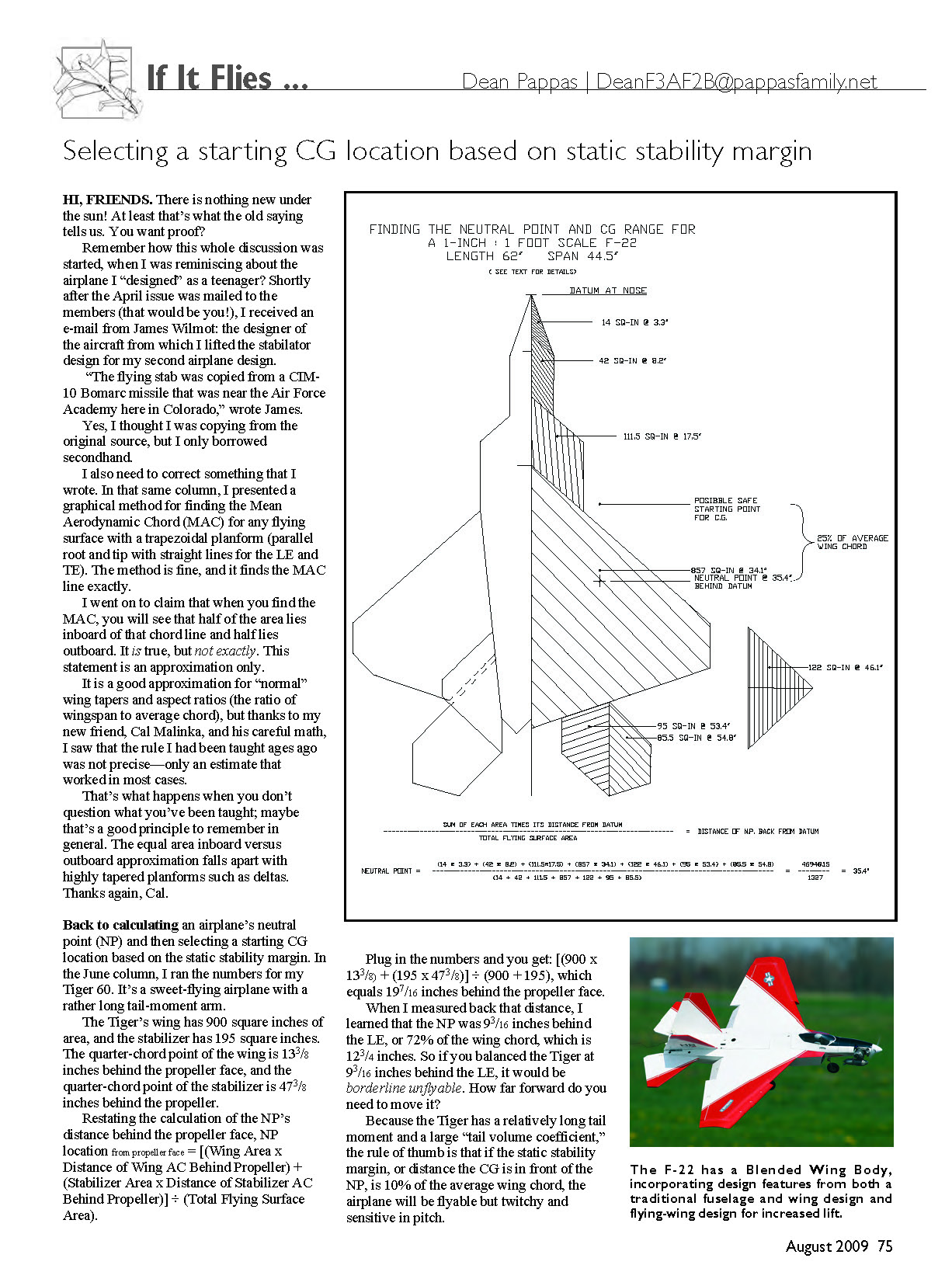
I obtained a picture of the F-22 that I found online and a copy of its basic specifications, such as wingspan and length. I performed the exercise that any scale modeler would go through if he or she were trying to draw plans for a model’s photographic documentation.
After carefully measuring a printout of the picture, I scaled it to 1 inch = 1 foot and drew the top view in CAD, yielding an airplane with a 62-inch length and a 44 1/2-inch wingspan. The total flying area at that size is close to 1,300 square inches, which would yield a sweet-flying airplane, even with the weight of a healthy electric-ducted-fan power plant. It’s yet another project I’ll never get to.
Then I reduced the drawing to straight lines that closely approximate the shape. That’s what you see with this column.
On the right, I cut that shape into deltas, trapezoids, and swept-wing-shaped sections, because those are the shapes for which we know how to calculate the mean aerodynamic centers. I fudged the right stabilator a bit, to make it into two neat trapezoids with the centerline parallel to the airplane centerline.
The F-22’s vertical fins are angled, so when viewed directly from the top, you don’t just see the tip but you see surface area. I fudged that outline a bit and made it into a delta shape. That “projected” area counts as a horizontal flying surface.
The same is true with V-tails and any other angled flying surfaces. (The same is true when looking at side area; when you look at the airplane from the side, wing dihedral and horizontal stabilizer dihedral or anhedral contribute to the side area.) I calculated the area of each one; the areas for left and right halves together are listed in the diagram next to the appropriate part. Then I plugged the areas and their distances from the nose into the same formula, as I did with the Tiger.
However, this time there were seven pieces, or terms, in the sum instead of just two for the wing and stabilizer. It’s the same simple formula—just more of it. The total area includes all seven pieces too.
The math is written out in the diagram, and the NP ends up only 1 1/4 inches behind the wing’s aerodynamic center. So if you had built an F-22 and balanced it at 25% of the wing’s MAC for starters, you would have had a tiger by the tail. Many pilots would be unlikely to complete the test flight successfully.
How much margin do we need? The F-22 is neither a flying wing, nor does it have a long tail moment. The tail moment is only roughly one wing chord, so the rule for stability margin represents an average of the cases discussed above—maybe a little closer to the flying wing case.
I would start with a CG that is close to 20% of the wing chord in front of the NP. The average wing chord is 22 inches, and I think I’d shoot for a starting balance point that is 27 or 28 inches back from the nose. That’s only 8 inches forward of the classic one-quarter-chord position on the wing that I’ve told you.
That rule is still good, but only for airplanes with "normal" tails. Sometimes you have to question things you were taught long ago.
I think I am out of space for now. Until we get together again, have fun and do take care of yourself.
MA
Transcribed from original scans by AI. Minor OCR errors may remain.

