
Model airplanes build character
Dean Pappas | [email protected]
The last two months have been hectic around here. The day job — actually a consulting gig — has had me working seven days a week all but one Sunday since I last sat at the keyboard to write to you all, and that has put a crimp in everything, not just flying. (My 16‑year‑old, the one with the wicked sense of humor, asked, "Mommy, who is that strange man?") Alas, we do what we have to do. That's not to say that my aeromodeling skills went completely unused these last few weeks.
The widget I've been working on during these long days is roughly the size of a two‑stroke .40 engine. It has four densely populated circuit boards and fiber‑optic equipment packed so tightly that the tall and short parts on one circuit board dovetail with short and tall parts on the next circuit board.
Who got to assemble the first one? My longtime workmate, Bob, turned to me as we admired the first one finished ("Look, Ma, no parts left!") and said, "It sure will be a good thing to have the assembly directions written by the guy who builds model airplanes." I learned all about that by building model airplanes too!
Contemplate, for a moment, the directions and plans for kits, ARFs, and even home appliances that require assembly that you have seen. Some of them are pretty darned good, while others stink to high heaven.
Good plans and assembly instructions are a thing of beauty, producing a meeting of the minds between designer and builder without their ever having to physically meet. I'll bet you never heard anyone wax poetic about assembly directions, but there is a first time for everything!
A well‑designed model with a good set of plans sticks in your mind. As a preteen, I remember building an airplane from a Graupner kit. I think it was a Taxi trainer. I couldn't read a single word of German, yet the directions were as clear as a bell, not to mention that I still remember the names of most of the parts of an airplane in German as a result of building that kit.
Recap: neutral point (NP) and center of gravity (CG)
The last two times we got together, I wrote about the notion of an airplane's neutral point (NP) and how the relationship between it and the center of gravity (CG) dictates whether the model is unstable, marginally stable, or nice and stable in pitch.
Retracing my steps, I examined the flying surfaces themselves and how the aerodynamic center (AC) of a flying surface represents the place where it can be said that both a constant nose‑down torque and the lift of that flying surface act. The AC, as it turns out, is usually one‑quarter of the way back from the leading edge (LE) on the mean aerodynamic chord (MAC).
Then I wrote about how to find the MAC on a variety of wing shapes with a simple graphical method. I used the straightforward seesaw analogy to figure the "balance point" of the wing's area and the stabilizer's area.
By doing that, I extended the idea of finding a wing's or stabilizer's AC to finding the entire aircraft's AC. We call this the airframe's NP; it's the point through which you could say that all of the model's lift acts. If the CG is in front of the NP, the airplane will be stable in pitch and will become unflyable as the CG moves behind the NP.
In the August issue I wrote about how to find the NP for an airframe that has a blended wing/body, such as an F‑22. It turns out that I have a buddy who wanted to know just that, and the timing was perfect.
The payoff after finding the NP is that you now know the place the CG has to be forward of to make the aircraft stable in pitch. I laid out a few rules of thumb for how much farther forward the CG has to be. With that, you'd think I would be finished with the subject.
Two important complicating factors
As it turns out, we are close to the finish line but we're not there yet. The problem is a little more complicated than I described several months ago.
The problem when explaining something such as this subject is how to introduce the complications. If I had described them up front, the prospect of trying to grapple with a complicated description would discourage the same readers I wanted to reach. So I started with the simple model of a seesaw.
Remember that seesaw calculation that used the wing and stabilizer areas? I used it to find a Goldberg Tiger 60's NP. The NP location I calculated with that method was a bit aft of the actual NP.
The reason is that several complicating factors were ignored. I will continue to ignore the smaller effects, such as the propeller and the vertical location of the wing and stabilizer compared to the airplane's thrust line.
On the other hand, it is time to add the two most important complicating factors. As it turns out, both move the eventual NP location forward, and that does matter, because the NP represents the farthest aft that you dare push the CG.
They are:
- The effect of low aspect ratio (AR) on the effective area of the tail.
- The effect of wing downwash on the tail.
Let's deal with them in that order.
Aspect ratio and lift slope
The Tiger uses a symmetrical airfoil on the wing and a flat‑plate airfoil on the stabilizer. I made the statement, back then, that the different airfoils didn't matter, because the lift per square inch of wing area changes by the same amount for each degree change in angle of attack (AOA).
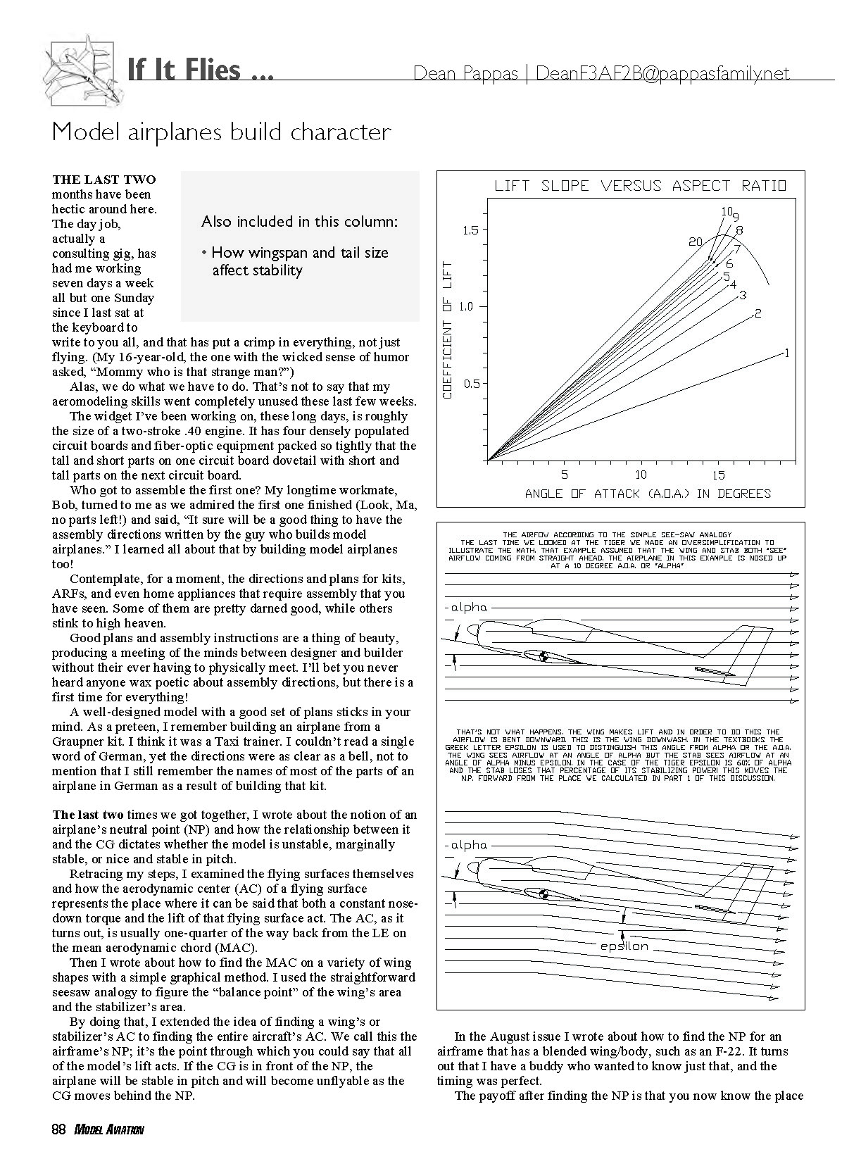
In proper math‑aero speak, the slope of the coefficient of lift (Cl) vs. AOA is the same for a wide variety of airfoils. I illustrated this with a diagram in the April issue.
It turns out that while airfoil choice has little to do with finding the NP, the aspect ratio (AR) of the flying surfaces does have a meaningful effect. Not all square inches are created equal.
The Cl vs. AOA for a flying surface is only the same as what aerodynamicists measure in a wind tunnel if the wing has a very high AR. Lower ARs reduce the lift slope.
AR is span divided by average chord. The higher the AR (skinnier the wing), the farther apart the wingtip vortices will be when measured in average wing chords. The wingtip vortices represent a loss of lift and additional drag, and the farther apart they are, the less wing efficiency is lost.
After rooting around in the old textbook pile, I found this approximation in Theory of Flight (von Mises, Prager, and Kuerti):
Cl (corrected for AR) = Cl (wind tunnel) × 1 ÷ (1 + 2 ÷ AR)
In English, this means that the lift vs. AOA slope is reduced by a factor that depends on the AR. That is only an approximation (it tends to overestimate the degradation with ARs less than 4), but it means that the wing on my Tiger 60 has an AR of 5.65, while the stabilizer has a much lower AR of 3.25. Therefore, every square inch of stabilizer area will be less effective than a square inch of wing area.
Let's figure out how much that effect has.
The wing has 900 square inches, and the correction factor for an AR of 5.65 is 74%. We could say that the wing behaves as if it had 665 square inches of wind‑tunnel area. The 195 square inches of stabilizer take a beating with its low AR. The AR of 3.25 gives a multiplier of 62%. The stabilizer works as if it has 121 square inches.
Yes, I am rounding the arithmetic. Now the seesaw formula for the NP gets the corrected wing and stabilizer areas.
NP location from propeller face = ([wing area × wing AC location from propeller face] + [stabilizer area × stabilizer AC location from propeller face]) ÷ (wing area + stabilizer area)
Plugging in the corrected areas:
NP location from propeller face = ([665 × 13 3/8] + [121 × 47 3/8]) ÷ (665 + 121) = 18 5/8 inches behind the propeller face.
That moved the NP 13/16 inch forward, to 8 3/8 inches behind the wing LE. That's now 65% of the wing chord behind the LE, and we still have to add the other big factor.
Downwash
Downwash: it's not hogwash.
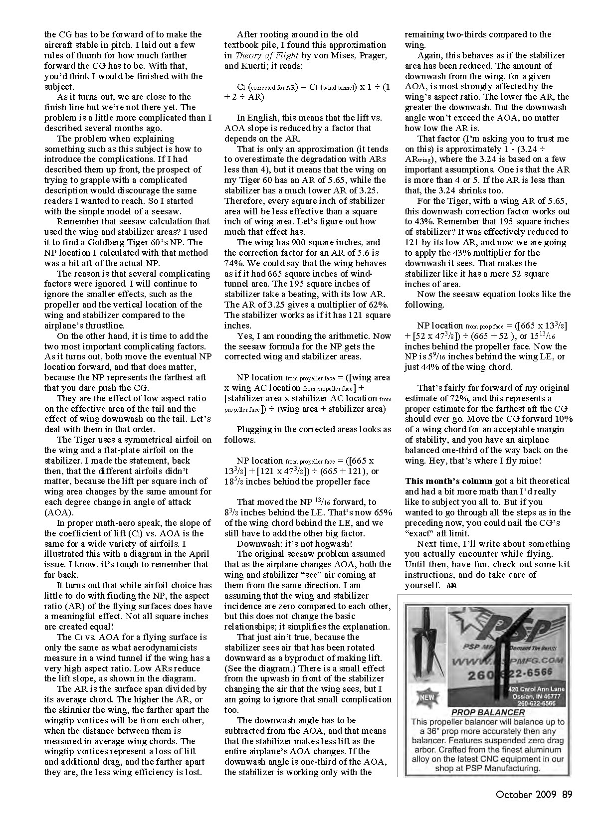
The original seesaw problem assumed that as the airplane changes AOA, both the wing and stabilizer "see" air coming at them from the same direction. I am assuming that the wing and stabilizer incidences are zero compared to each other; this does not change the basic relationships but simplifies the explanation.
That just ain't true, because the stabilizer sees air that has been rotated downward as a byproduct of making lift. There is a small effect from the upwash in front of the stabilizer changing the air that the wing sees, but I am going to ignore that small complication too.
The downwash angle has to be subtracted from the AOA, and that means that the stabilizer makes less lift as the entire airplane's AOA changes. In the case of the Tiger, the downwash is one‑third of the AOA, so the stabilizer is working only with the remaining two‑thirds compared to the wing.
Again, this behaves as if the stabilizer area has been reduced. The amount of downwash from the wing, for a given AOA, is most strongly affected by the wing's AR. The lower the AR, the greater the downwash. But the downwash angle won't exceed the AOA, no matter how low the AR is.
That factor (approximately) is 1 − (3.24 ÷ ARwing), where the 3.24 is based on a few important assumptions. One is that the AR is more than 4 or 5. If the AR is less than that, the 3.24 shrinks too.
For the Tiger, with a wing AR of 5.65, this downwash correction factor works out to 43%. Remember that 195 square inches of stabilizer? It was effectively reduced to 121 by its low AR, and now we apply the 43% multiplier for the downwash it sees. That makes the stabilizer act like it has a mere 52 square inches of area.
Now the seesaw equation looks like this:
NP location from propeller face = ([665 × 13 3/8] + [52 × 47 3/8]) ÷ (665 + 52) = 15 13/16 inches behind the propeller face.
Now the NP is 5 9/16 inches behind the wing LE, or just 44% of the wing chord.
That's fairly far forward of my original estimate of 72%, and this represents a proper estimate for the farthest aft the CG should ever go. Move the CG forward 10% of a wing chord for an acceptable margin of stability, and you have an airplane balanced one‑third of the way back on the wing. Hey — that's where I fly mine!
This month's column got a bit theoretical and had a bit more math than I'd really like to subject you all to. But if you wanted to go through all the steps as in the preceding, you could nail the CG's "exact" aft limit.
Next time, I'll write about something you actually encounter while flying. Until then, have fun, check out some kit instructions, and do take care of yourself.
—MA
Transcribed from original scans by AI. Minor OCR errors may remain.

