
If It Flies ... - 2009/12
Evidence of when the CG location is just right
Dean Pappas
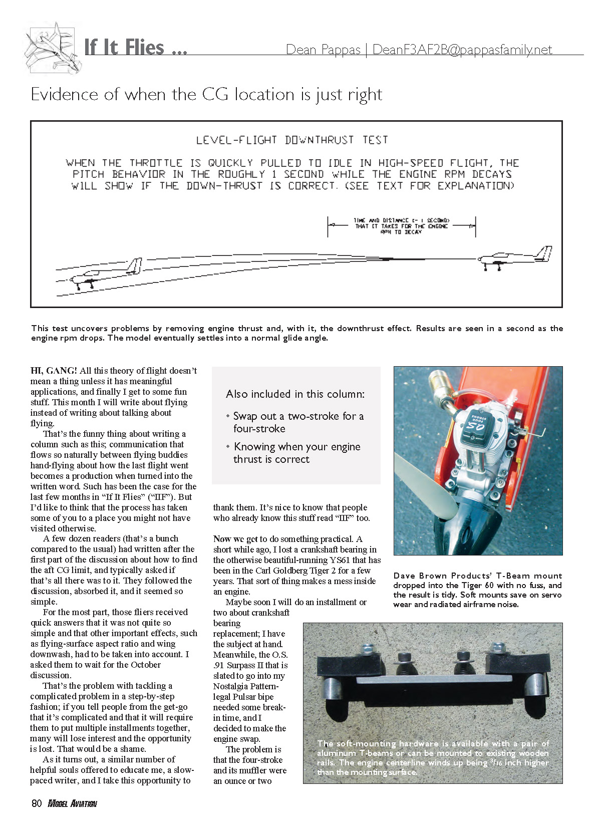
Level-flight downthrust test
When the throttle is quickly pulled to idle in high-speed flight, the pitch behavior in the roughly 1 second while the engine RPM decays will show if the downthrust is correct. (See text for explanation.)
Time and distance (~1 second) that it takes for the engine RPM to decay
This test uncovers problems by removing engine thrust and, with it, the downthrust effect. Results are seen in a second as the engine RPM drops. The model eventually settles into a normal glide angle.
Hi, gang! All this theory of flight doesn’t mean a thing unless it has meaningful applications, and finally I get to some fun stuff. This month I will write about flying instead of writing about talking about flying.
That’s the funny thing about writing a column such as this; communication that flows so naturally between flying buddies hand-flying about how the last flight went becomes a production when turned into the written word. Such has been the case for the last few months in “If It Flies” (“IIF”). But I’d like to think that the process has taken some of you to a place you might not have visited otherwise.
A few dozen readers (that’s a bunch compared to the usual) wrote after the first part of the discussion about how to find the aft CG limit, and typically asked if that’s all there was to it. They followed the discussion, absorbed it, and it seemed so simple.
For the most part, those fliers received quick answers that it was not quite so simple and that other important effects, such as flying-surface aspect ratio and wing downwash, had to be taken into account. I asked them to wait for the October discussion.
That’s the problem with tackling a complicated problem in a step-by-step fashion; if you tell people from the get-go that it’s complicated and that it will require them to put multiple installments together, many will lose interest and the opportunity is lost. That would be a shame.
As it turns out, a similar number of helpful souls offered to educate me, a slow-paced writer, and I take this opportunity to thank them. It’s nice to know that people who already know this stuff read “IIF” too.
Also included in this column:
- Swap out a two-stroke for a four-stroke
- Knowing when your engine thrust is correct
Now we get to do something practical. A short while ago, I lost a crankshaft bearing in the otherwise beautiful-running YS61 that has been in the Carl Goldberg Tiger 2 for a few years. That sort of thing makes a mess inside an engine.
Maybe soon I will do an installment or two about crankshaft bearing replacement; I have the subject at hand. Meanwhile, the O.S. .91 Surpass II that is slated to go into my Nostalgia Pattern–legal Pulsar biplane needed some break-in time, and I decided to make the engine swap.
The problem is that the four-stroke and its muffler were an ounce or two heavier than the YS and Hatori muffler they were to replace. The Tiger flew sweetly and I was happy with it. But I suspected that it was the least bit nose-heavy, and this engine change would make it more so.
I’ll describe (without the hand-flying) what made me think that the CG was almost right.
The Tiger was balanced almost spot-on at one-third of the wing chord. It flew nicely, the elevator trim was centered, or at least looked to be, and the airplane transitioned to a nice glide when the engine was idled. On top of that, straight and level inverted flight required only a small amount of down elevator, which tends to confirm that the CG is not too far forward. The CG shift would be small.
The problem was that while the Tiger would spin and snap roll beautifully inverted, or in the negative-G direction, both the spin and snap were a bit “barrely” in the positive-G direction. While the inverted spin rotated tightly and slowly with only elevator and rudder application (indicating a deeply stalled autorotation), the upright spin sometimes unstalled and started to spiral out, unless aileron control was held during the entire spin.
Inside and outside snap rolls told a similar story. Outsides started and stopped crisply, while inside (or up-elevator) snaps barrel-rolled for maybe one-quarter of a turn before the Tiger would "wind in" and rotate quickly. The exits were still nice and clean.
Many models spin and snap roll better in the negative-G direction. It's a consequence of almost every design feature that gives an airplane stability, such as dihedral.
As part of the .91 four-stroke installation, I moved the CG aft 1/4 inch for starters. That works out to a lousy 2% of the mean aerodynamic chord. However, if you are moving the CG aft in nonrisky, incremental steps, this is a good step size. Fliers who fine-tune subtle flying characteristics often take steps half this big. As it turned out, I won't bother moving it any more.
The original 60-size engine installation in the Tiger used a Dave Brown Products VibraDamp Sport Beam, but that would not do for the four-stroke. Those engines often require some sort of nose-ring restraint, and I did not want to add that structure to the front of the model. Someday after the O.S. migrates to its intended home, I will probably replace the rebuilt YS in its old home.
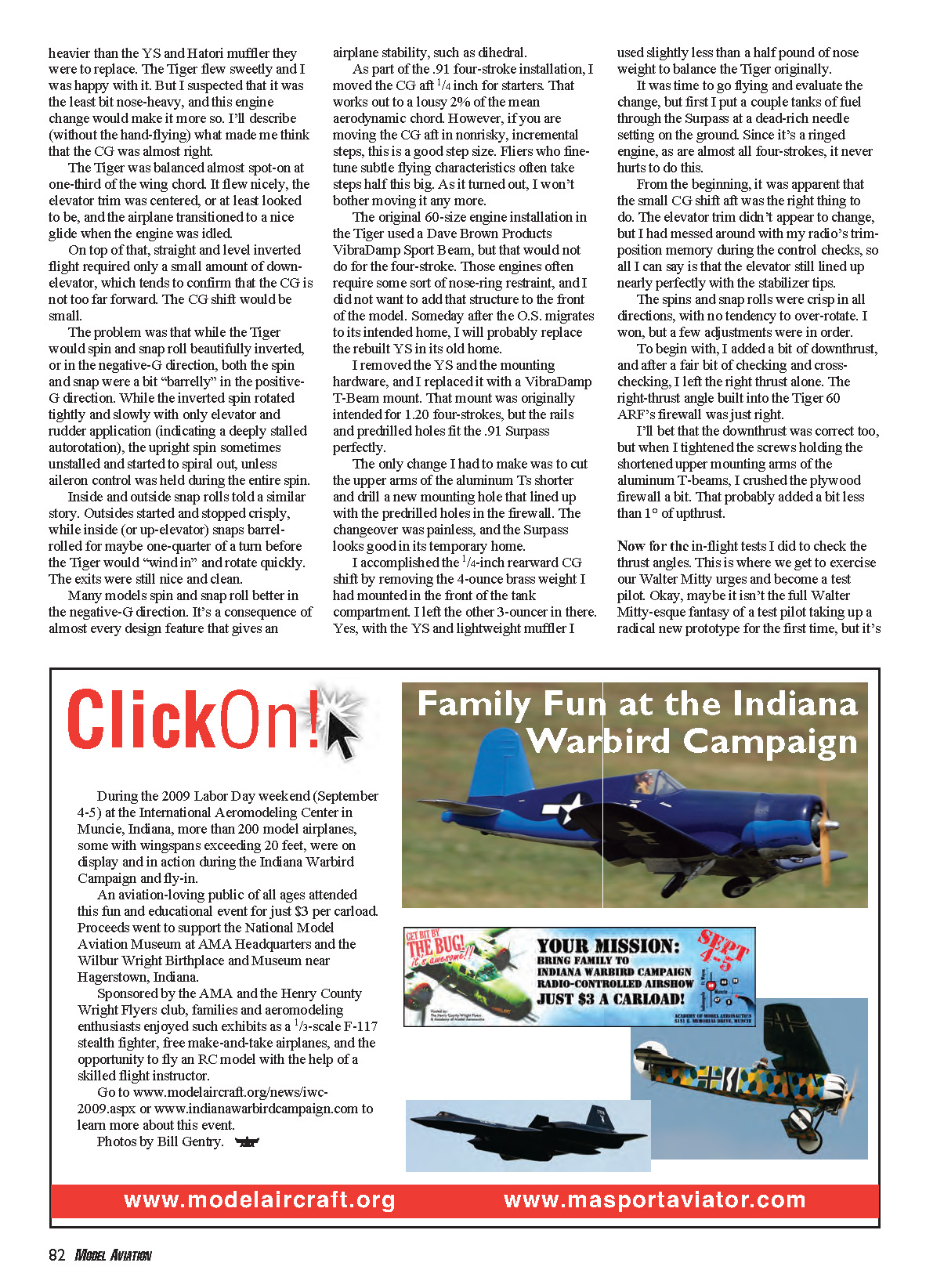
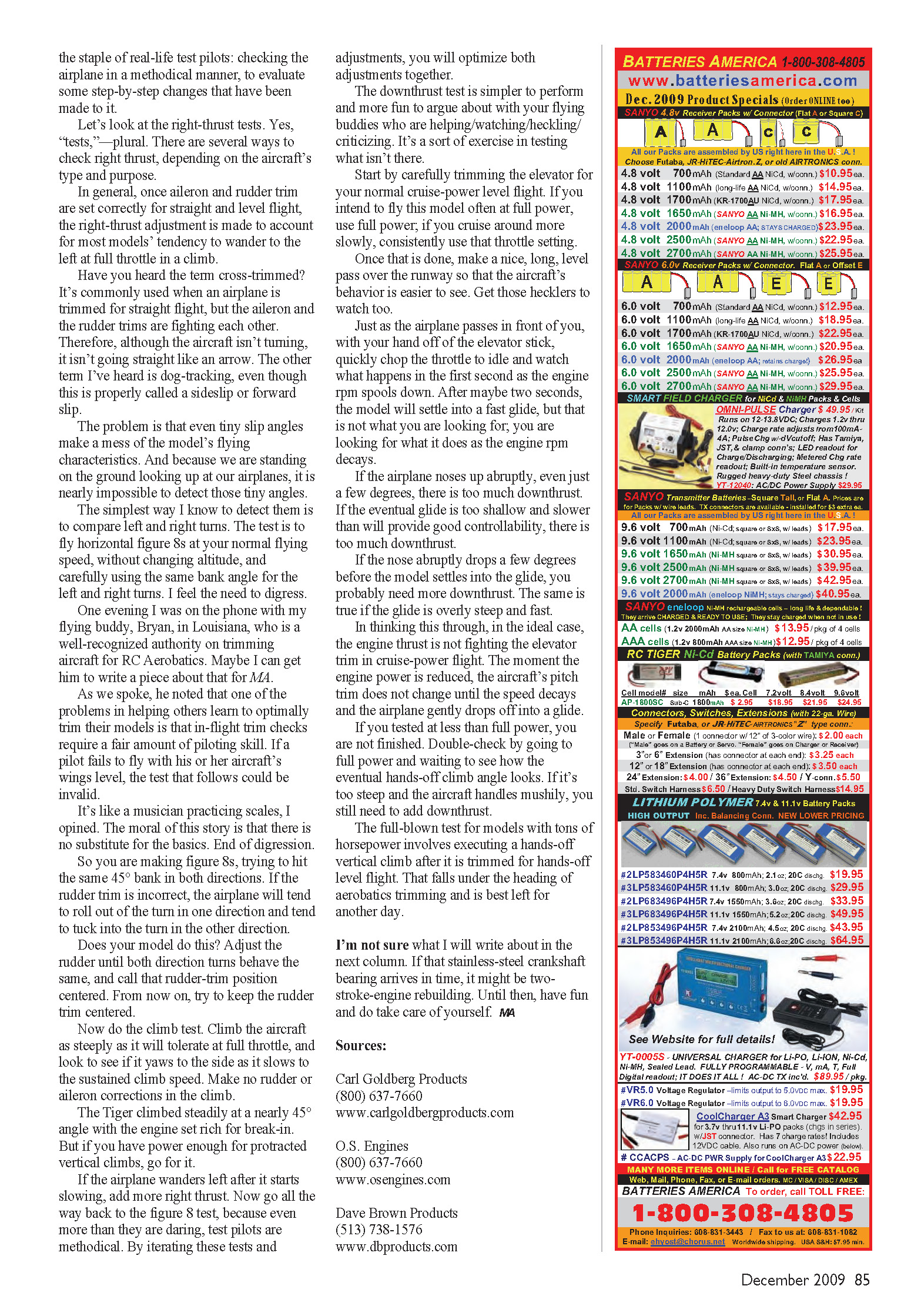
I removed the YS and the mounting hardware, and I replaced it with a VibraDamp T-Beam mount. That mount was originally intended for .120 four-strokes, but the rails and predrilled holes fit the .91 Surpass perfectly.
The only change I had to make was to cut the upper arms of the aluminum T's shorter and drill a new mounting hole that lined up with the predrilled holes in the firewall. The changeover was painless, and the Surpass looks good in its temporary home.
I accomplished the 1/4-inch rearward CG shift by removing the 4-ounce brass weight I had mounted in the front of the tank compartment. I left the other 3-ounce one in there. Yes, with the YS and lightweight muffler I used slightly less than a half pound of nose weight to balance the Tiger originally.
It was time to go flying and evaluate the change, but first I put a couple tanks of fuel through the Surpass at a dead-rich needle setting on the ground. Since it's a ringed engine, as are almost all four-strokes, it never hurts to do this.
From the beginning, it was apparent that the small CG shift aft was the right thing to do. The elevator trim didn't appear to change, but I had messed around with my radio's trim-position memory during the control checks, so all I can say is that the elevator still lined up nearly perfectly with the stabilizer tips.
The spins and snap rolls were crisp in all directions, with no tendency to over-rotate. I won, but a few adjustments were in order.
To begin with, I added a bit of downthrust, and after a fair bit of checking and cross-checking, I left the right thrust alone. The right-thrust angle built into the Tiger 60 ARF's firewall was just right.
I'll bet that the downthrust was correct too, but when I tightened the screws holding the shortened upper mounting arms of the aluminum T-beams, I crushed the plywood firewall a bit. That probably added a bit less than 1° of upthrust.
Now for the in-flight tests I did to check the thrust angles. This is where we get to exercise our Walter Mitty urges and become a test pilot. Okay, maybe it isn't the full Walter Mitty-esque fantasy of a test pilot taking up a radical new prototype for the first time, but it's fun. This test uncovers problems by removing engine thrust and, with it, the downthrust effect. Results are seen in a second as the engine RPM drops. The model eventually settles into a normal glide angle.
This is the staple of real-life test pilots: checking the airplane in a methodical manner to evaluate some step-by-step changes that have been made to it.
Let's look at the right-thrust tests. Yes, "tests"—plural. There are several ways to check right thrust, depending on the aircraft's type and purpose.
In general, once aileron and rudder trim are set correctly for straight and level flight, the right-thrust adjustment is made to account for most models' tendency to wander to the left at full throttle in a climb.
Have you heard the term cross-trimmed? It's commonly used when an airplane is trimmed for straight flight, but the aileron and the rudder trims are fighting each other. Therefore, although the aircraft isn't turning, it isn't going straight like an arrow. The other term I've heard is dog-tracking, even though this is properly called a sideslip or forward slip.
The problem is that even tiny slip angles make a mess of the model's flying characteristics. And because we are standing on the ground looking up at our airplanes, it is nearly impossible to detect those tiny angles.
The simplest way I know to detect them is to compare left and right turns. The test is to fly horizontal figure 8s at your normal flying speed, without changing altitude, and carefully using the same bank angle for the left and right turns.
I feel the need to digress. One evening I was on the phone with my flying buddy, Bryan, in Louisiana, who is a well-recognized authority on trimming aircraft for RC aeronautics. Maybe I can get him to write a piece about that for MA.
As we spoke, he noted that one of the problems in helping others learn to optimally trim their models is that in-flight trim checks require a fair amount of piloting skill. If a pilot fails to fly with his or her aircraft's wings level, the test that follows could be invalid.
It's like a musician practicing scales, I opined. The moral of this story is that there is no substitute for the basics. End of digression.
So you are making figure 8s, trying to hit the same 45° bank in both directions. If the rudder trim is incorrect, the airplane will tend to roll out of the turn in one direction and tend to tuck into the turn in the other direction.
Does your model do this? Adjust the rudder until both direction turns behave the same, and call that rudder-trim position centered. From now on, try to keep the rudder trim centered.
Now do the climb test. Climb the aircraft as steeply as it will tolerate at full throttle, and look to see if it yaws to the side as it slows to the sustained climb speed. Make no rudder or aileron corrections in the climb.
The Tiger climbed steadily at a nearly 45° angle with the engine set rich for break-in.
But if you have power enough for protracted vertical climbs, go for it.
If the airplane wanders left after it starts slowing, add more right thrust. Now go all the way back to the figure 8 test, because even more than they are daring, test pilots are methodical. By iterating these tests and adjustments, you will optimize both adjustments together.
The downthrust test is simpler to perform and more fun to argue about with your flying buddies who are helping/watching/heckling/criticizing. It's a sort of exercise in testing what isn't there.
Start by carefully trimming the elevator for your normal cruise-power level flight. If you intend to fly this model often at full power, use full power; if you cruise around more slowly, consistently use that throttle setting.
Once that is done, make a nice, long, level pass over the runway so that the aircraft's behavior is easier to see. Get those hecklers to watch too.
Just as the airplane passes in front of you, with your hand off of the elevator stick, quickly chop the throttle to idle and watch what happens in the first second as the engine RPM spools down. After maybe two seconds, the model will settle into a fast glide, but that is not what you are looking for; you are looking for what it does as the engine RPM decays.
If the airplane noses up abruptly, even just a few degrees, there is too much downthrust. If the eventual glide is too shallow and slower than will provide good controllability, there is too much downthrust.
If the nose abruptly drops a few degrees before the model settles into the glide, you probably need more downthrust. The same is true if the glide is overly steep and fast.
In thinking this through, in the ideal case, the engine thrust is not fighting the elevator trim in cruise-power flight. The moment the engine power is reduced, the aircraft's pitch trim does not change until the speed decays and the airplane gently drops off into a glide.
If you tested at less than full power, you are not finished. Double-check by going to full power and waiting to see how the eventual hands-off climb angle looks. If it's too steep and the aircraft handles mushily, you still need to add downthrust.
The full-blown test for models with tons of horsepower involves executing a hands-off vertical climb after it is trimmed for hands-off level flight. That falls under the heading of aerobatics trimming and is best left for another day.
I'm not sure what I will write about in the next column. If that stainless-steel crankshaft bearing arrives in time, it might be two-stroke-engine rebuilding. Until then, have fun and do take care of yourself. MA
Sources
- Carl Goldberg Products
- (800) 637-7660
- www.carlgoldbergproducts.com
- O.S. Engines
- (800) 637-7660
- www.osengines.com
- Dave Brown Products
- (513) 738-1576
- www.dbproducts.com
Transcribed from original scans by AI. Minor OCR errors may remain.

