
The classic 2-4 Stunt setup
Dean Pappas | [email protected]
Hi, gang. Every once in a while we look back on our own work with great satisfaction—maybe it’s a particularly good landing or a nice bit of woodwork in the workshop. The satisfaction that comes from taking a well-considered, critical look at our pleasing work is real.
I’ll tell you what else is real. It’s that little twinge of dissatisfaction when you look back at something you did and it doesn’t quite “measure up.” Fortunately this provides motivation to get it right next time.
I recently reread October’s “If It Flies … ” and realized that my thoughts must have been scattered. At least that’s the way it looked to me upon reviewing it more than a month after submission. How to make it right?
I thought about that for a while. It occurred to me that merely explaining things a different way would work, but that repeating myself would be a waste of your time. Then it hit me: explaining the basics of a classic CL Precision Aerobatics (Stunt) “run” would allow me to tie things together, and it would also give me an opportunity to write about something other than RC while still helping fix the leaks in the last column.
The classic “2-4 break” CL Stunt engine setup is a marvel of subtle sophistication. It’s a quintessential aeromodeler’s solution to a difficult problem. Long before computer radios, autopilots, and all manner of electronic wizardry, this simple-looking but fiendishly clever arrangement—with the barest minimum moving parts and nothing that looks like a control system—evolved to keep the speed of a CL Stunter nearly constant despite the vertical climbs and dives of the Stunt pattern.
What’s a Stunt pattern?
That’s a fair question, especially if you’ve never seen it flown. You can find the online AMA rule book at the address I have included in the “Sources” listing. The old rule book illustrations were perspective drawings that showed how the maneuvers were drawn on the surface of a hemisphere; they show the schedule better than the new “flat” drawings in the rule book. The updated descriptions do a better job of describing some of the geometric nuances.
YouTube has numerous videos showing CL Stunt patterns, although the quality of the videography sometimes leaves much to be desired. Search under “CL Stunt” and “F2B,” and a mess of results pops up. Several show world-class pilots flying. The site addresses are under “Sources.”
One video depicts an electric-powered F2B flight. It might seem strange to open with this, but the film is unusual in that the fixed camera installation was done properly and in the right spot to see the entire pattern flown well. The pilot is doing a decent job of it too!
Because CL fliers often perform with several circles next to each other, it is difficult to film clips without the sound of other models. I found a video of a pilot who does not fly a “book” schedule, or even rule book maneuvers, but the engine setup is a classic Stunt run, with a deep break in maneuvers. If you listen carefully, you can even hear the engine briefly break lean after the corners of the square loops, precisely when the airplane scrubs off speed in the corners.
Videos to watch (examples)
- “Nice Flying Footage of Kevin’s Tsunami” — shows a performance that does not demonstrate a full pattern. The old “G”-series SuperTigre light-case .60 has a nice deep break between rich and lean. Notice how the needle setting results in the engine oscillating between a fast four-cycle and a rich two-cycle while the pilot walks out to the handle.
- “Bill Werwage Classic Flight VSC14” — shows a killer engine run from the three-time World Champion during the Vintage Radio Control Society nostalgia meet. Unfortunately other flights are taking place at the same time, making this difficult listening music, but the setup does everything right in what looks to have been windy conditions.
- “C/L Stunt Al’s Snaggletooth” — footage of Al Rabe (world vice-champion in 1978) with his semiscale P-51 “Snaggletooth.” This video shows the low-break setup described in the text; the benefit is that the system is less laggy when responding to changes in propeller load.
- “Fitzgerald” — illustrates the more modern tuned-pipe Stunt setup, flown by several-time World Champ Dave Fitzgerald. It sounds different from the classic 2-4 break setup and many between-maneuver laps have been deleted, so the clip is short. In this video, the changes in scavenging and torque are dictated by exhaust tuning.
If you watched and listened to all of the preceding film clips (and maybe a few others), did you notice how the engines appear to lean out going uphill and then richen and "go flat" coming downhill? That's what keeps the model from slowing too much in a climb and then from coming downhill in a screaming-fast dive.
You might even notice that the changes sound like they happen a bit late compared to when the airplane actually changes direction. This is less than ideal, but still, this basic arrangement has worked well for more than a half century.
The “break”
What arrangement? For one thing, notice that all of these engines sound somewhat rich. The fuel-to-air mixtures are not set for maximum rpm; instead they are set where the torque that the power plant delivers changes abruptly for very small needle valve movements. This is "the break."
Just on the rich side of the break, the rich mixture delays the onset of combustion and excess fuel in the combustion chamber keeps the maximum temperature and cylinder pressure low. This means less torque and, as a result, less horsepower.
If you are poised just on the rich side of the break, one lousy little click leaner on the needle valve will change the whole picture. The compression heating lights the fire a bit sooner, and the combustion process progresses more quickly. The more advanced ignition timing produces more torque. And if the rpm rises, the compression heating effect is enhanced, making even more torque and horsepower.
Do you remember how one film clip showed the engine hopping back and forth across the break? That leads into the other key element.
Venturi and scavenging
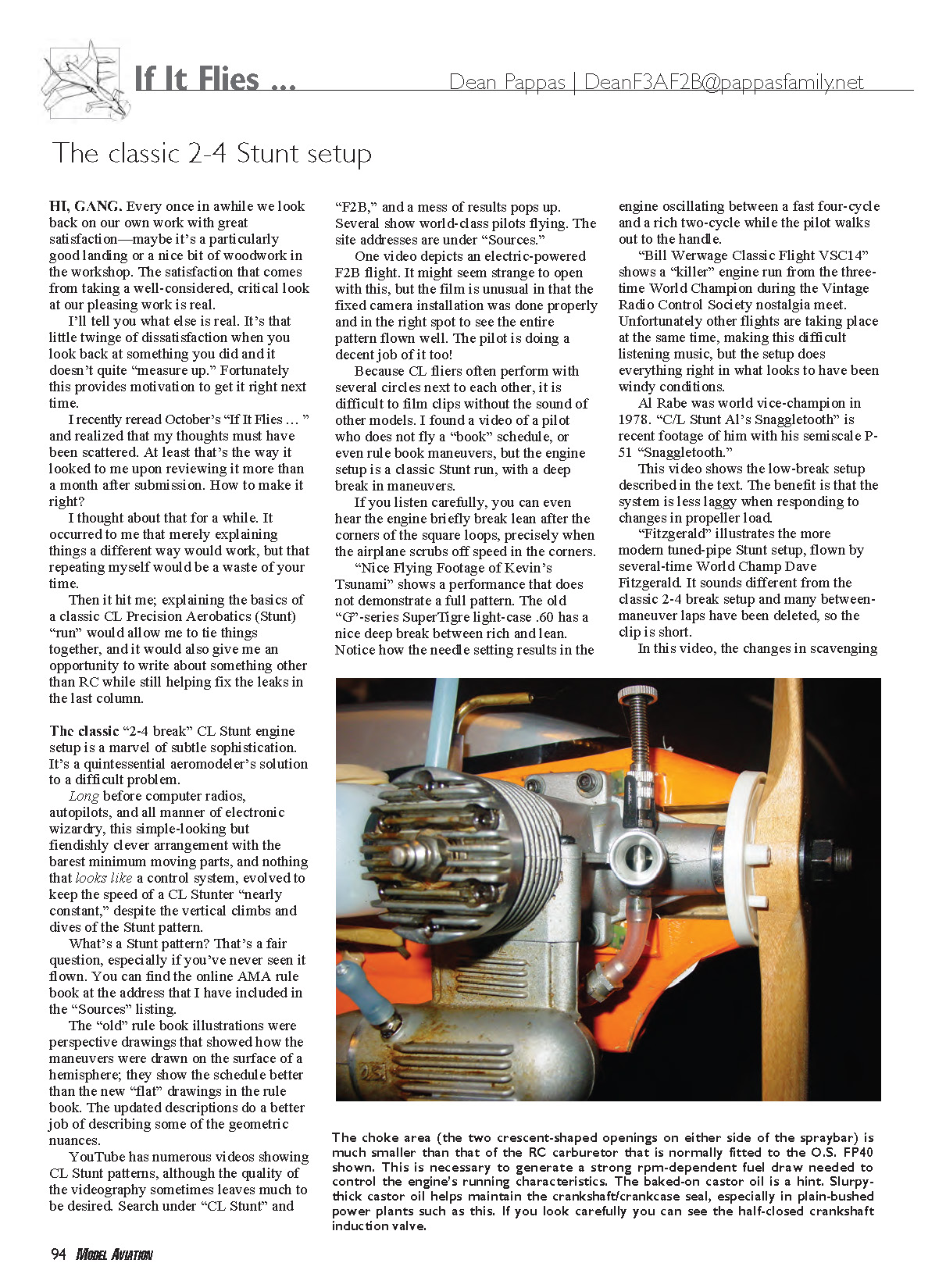
The other key to the classic 2-4 Stunt setup is the small carburetor or venturi used with a CL Stunt engine. All engines are air pumps, and our single-cylinder two-strokes are particularly interesting.
Think of them as two-stage air pumps. Air is sucked into the crankcase through the crankshaft valve every time the piston is on the upstroke. Stunters have no need for throttles, so they have simple full-throttle-only carburetors or venturis. They are not actually so simple, but that is another matter.
If you look into the venturi, or open carburetor of an RC engine, you'll see that the crankshaft valve is completely open for roughly one-eighth of a revolution before the piston reaches TDC (Top Dead Center). This is, in part, because it takes time to accelerate the air through the venturi, down the central passage in the crankshaft, and up into the crankcase.
The crankshaft valve takes approximately one-half of a revolution from when it starts to open until it finally closes. So by the time it does close, the piston is already on its way downward and squeezing the air/fuel mixture from the crankcase upward through the bypasses into the combustion chamber.
The momentum of the air/fuel mix matters during this transition from crankcase suction to compression. At nearly the same time that this transition occurs, the exhaust port opens and exhaust gases are expelled at high pressure and velocity. As a result of this sudden acceleration, they have plenty of momentum. And as the last of the exhaust rushes out into the muffler, its momentum keeps it moving even after the pressure in the cylinder has dropped.
The result is actually a vacuum, and 10° or 20° of rotation later the bypasses open, allowing the intake mixture to be sucked into the combustion chamber by the vacuum that is left there. That is called scavenging. Depending on the time relationship of all port and valve openings and closings, the engine will have its best scavenging in some rpm range that the manufacturer has designed.
The venturi (remember the venturi?) is typically designed to maximize the amount of vacuum generated in it as the air is sucked through it into the crankcase. This is what draws the fuel into the engine in the first place.
Assuming that the engine is running in that rpm range in which the designer has provided good scavenging, the vacuum that draws in the fuel will be strongly influenced by changes in rpm. More rpm will draw a better vacuum in the venturi, which will improve fuel draw and provide more fuel.
If the cross-sectional area or opening of the venturi is small enough, it will drive the engine rich with increased rpm. If it is slightly larger, it will simply be adequate for the increased needs of the engine at high rpm. If it is too large, the engine will suffer from poor fuel draw during climbs and maneuvers.
That is why you can't always put a bigger carburetor on an engine to get more horsepower. It also explains why the tiniest air leak in the crankcase will ruin the fuel draw.
Leak sources and shaft seals
Where are those potential leak sources?
- Loose backplate screws.
- Loose screws or worn O-rings under the carburetor/venturi.
- Worn bushings or worn/loose ball bearings on the crankshaft.
The crankshaft and the way it fits into the crankcase create a long rotating seal. Fuel and condensed oil between the two parts form the seal. This works great if the gaps are only two or three thousandths of an inch!
Worn bushings or even worn/loose ball bearings allow the shaft to wiggle and break this oil seal. Sometimes a loose bearing will allow a bit of the aluminum crankcase to wear away, and even a bearing replacement will not fix the problem. This leads to the engine being unable to hold a vacuum and the fuel draw will be ruined. It will also make it difficult to obtain a consistent mixture as it warms up.
How the system stabilizes speed
So with a small venturi providing a strong rpm-dependent fuel mixture, and the break providing a strong change in torque with small changes in mixture, we have the makings of a stable system for keeping the airplane’s flying speed within bounds during maneuvers.
The rpm must increase some during dives and drop during climbs, but the change in torque that the break provides allows the horsepower to increase despite the reduced rpm in a climb. Similarly, the reduction in torque as the rich mixture cools the fire and retards the ignition timing will reduce the delivered horsepower despite increased rpm in dives.
If you go back and listen to some of those online videos, you might be able to pick out the difference between the “flat” note of a rich mixture and the slight increase in diving rpm that caused it. With a little more careful attention you can pick the “clean” note during climbs apart from the slight rpm drop.
The first time you heard it, the dominance of high harmonics in the exhaust note might have convinced you that the rpm is higher during the climb, but that isn’t the case. In-flight measurements with data loggers have proven this not to be the case.
Tuning considerations and trade-offs
If you take an engine that has been set up this way and increase the compression ratio slightly, it will “break” at slightly lower rpm and with a slightly richer needle valve setting. The change in torque that the break provides will be greater too, but the engine will also lag behind the changes in rpm more. Once the engine breaks lean, the added power creates more heat, which tends to keep it from richening as easily.
In the dive, after the engine breaks rich, the cooling of just a few degrees caused by the added fuel will delay the break back to lean. Add a little too much compression, and the first time the engine breaks lean, the added heat is enough to keep it there until the entire tank is emptied. That is what the Stunt pilots call a “runaway,” and the strong-breaking setups will run away if the needle valve is set only a few clicks too lean. Yes, this is an important skill for Stunt fliers!
If instead you drop the compression a bit, you get slightly less break and an engine that performs this bit of magic at higher rpm, which can be used to run a lower-pitch propeller. You can use those to provide dive brakes instead of a deep-break rich. This describes the run of the Snaggletooth featured in one of the videos.
Another time I should write about fuel tank design. The Stunt pilots have a treasure trove of knowledge here, and much of it is genuinely useful in RC as well.
Right now I am going to organize some of the work I’ve been doing recently on my true constant-rpm electric-powered Stunt setup. I’ll be back in the February 2011 issue. Until then, have fun, and do take care of yourself.
Want to learn more about two-stroke scavenging? It’s quite a subject. A great book that has been out of print for years is Gordon Jennings’ Two-Stroke Tuner’s Handbook. You can probably find online copies in a variety of places; I have included the Web site address for one resource in the “Sources” listing.
Sources
- AMA CL Stunt rules: http://bit.ly/db6WQt
- Electric F2B video: http://bit.ly/aqpz6x
- “Nice Flying Footage of Kevin’s Tsunami”: http://bit.ly/awAeRr
- “Bill Werwage Classic Flight VSC14”: http://bit.ly/9wLOJj
- “C/L Stunt Al’s Snaggletooth”: http://bit.ly/9ZS8XX
- “Fitzgerald”: http://bit.ly/c5payH
- Two-Stroke Tuner’s Handbook (Gordon Jennings): http://edj.net/2stroke/jennings
Transcribed from original scans by AI. Minor OCR errors may remain.

