
Two of the Big Five model misadjustments
Hi, gang! The literature is full of tales of great deeds and glorious victories won by noble heroes wielding mighty swords. Let's face it: this is the sort of stuff that makes for good storytelling.
Those swords were often described in great detail, their origins shrouded in mystery—sometimes as emblems of a craftsman's devotion, made to honor ancestors, or even attributed to deity. Never would the legends describe these weapons as clumsy in the hand, crooked, or ill balanced.
Now, that wouldn't do at all, would it? Of course not. It doesn't work with swords, real or legendary, and it doesn't work with airplanes either.
We aeromodelers sharpen our swords in two primary ways: with care in the workshop and with systematic adjustments or trimming on the flying field. That is what I'd like to talk about. This isn't necessarily difficult or time-consuming stuff; mostly it consists of little tweaks—the sorts of things you can do between flights at the field while watching and helping your clubmates.
Come to think of it, this can be one of those conversation starters in the pits that help us all brush the mundane world aside and focus on having fun with our flying buddies.
There are five adjustments—or misadjustments—that I see most often at the flying field. These are not typically showstoppers in the crash-causing sense. Instead, they make an airplane a little harder to fly than it ought to be. That makes it more difficult to look good while doing your thing—whatever that is.
Imagine going into battle, not with comic-strip hero Prince Valiant's Singing Sword, but instead with a misbalanced Stinging Sword that hurts the hands with every blow, like being hit with the end of a baseball bat.
Okay, maybe badly balanced airplanes are not the same as badly balanced swords, but both are harder to use than they ought to be. The big five are:
- Control surface hinge-line gaps
- Heavy wingtip or lateral misbalance
- Balance point, usually referred to as CG
- Engine thrust—both downthrust and right thrust
- Aileron differential and adverse yaw
We won’t get through all five today; I’ll cover two of them.
Hinge Gaps
Air is tricky stuff that resists all too many of our efforts to tame it; just ask a race car aerodynamicist. Let’s look at how a control surface does its thing.
The point of a control surface such as an aileron, elevator, or rudder is to change the direction of the flow off of the trailing edge and, in so doing, change the camber of the flying surface. That creates lift in the desired direction, and the force (more properly, “torque”) needed to deflect the control surface is called control effort.
At the very least, hinge gaps waste control effort by “leaking” high-pressure air from one side of the flying surface to the other. This leakage reduces the control force that a deflected control surface produces and has other, more undesirable, effects.
These ugly side effects become worse at low speed and with large control deflections, which often means that takeoff and landing are the most affected flight regimes. That’s when solid controllability is most important, right? In particular, I’ll focus on the effects on pitch and roll control.
Have you ever had an airplane that landed nicely if you kept the speed up a bit, but the elevator didn’t have enough control authority to make the model flare out if you slowed too much? Loss of elevator power on landing is a common problem.
I’m not talking about stalling the airplane; what I mean is that the elevator effectiveness peters out while the wing still has plenty of lift, forcing you to land faster than you would like. There is almost nothing as pretty as a nose-high full-stall landing, and that requires ample elevator power while flying close to the stall speed.
Sometimes this problem is caused by design (very short tail moment), and sometimes it’s caused by nose-heaviness. Short tail moments, as found on many scale designs, can make an airplane susceptible to this problem, and even slight nose-heaviness will make things much worse.
In either case, the additional loss of control power caused by hinge-line leakage will happen at the worst time, when the control surface is deflected the most and airspeed is the least.
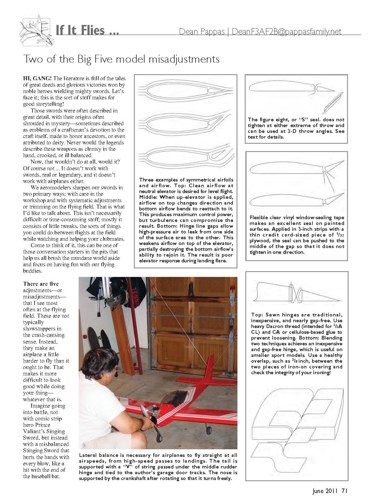
Leakage is at its worst at precisely that moment. Let’s see why. It might be helpful to imagine the progression shown in accompanying diagrams: a symmetrical stabilizer and elevator in level flight with no deflection—then the elevator sharply deflected upward for a landing flare. The abrupt change in airflow direction on both the top and bottom sides of the airfoil results in a large pressure difference across the hinge line.
The high pressure on top will try to leak through given a chance. That chance is a gap between the elevator and stabilizer. The result is a sheet of air that squirts through the gap and distorts the flow as it moves around the outside of the hinge line. This reduces the effectiveness of the elevator and creates extra drag.
We need to seal the hinge gaps. This includes not only the elevator, but also the ailerons. Actually, aileron hinge-line gaps can be even more of a problem when it comes to messing up a model’s friendly flying characteristics. There is nothing fancy about fixing this, and it’s simple to do—and it often fixes several problems.
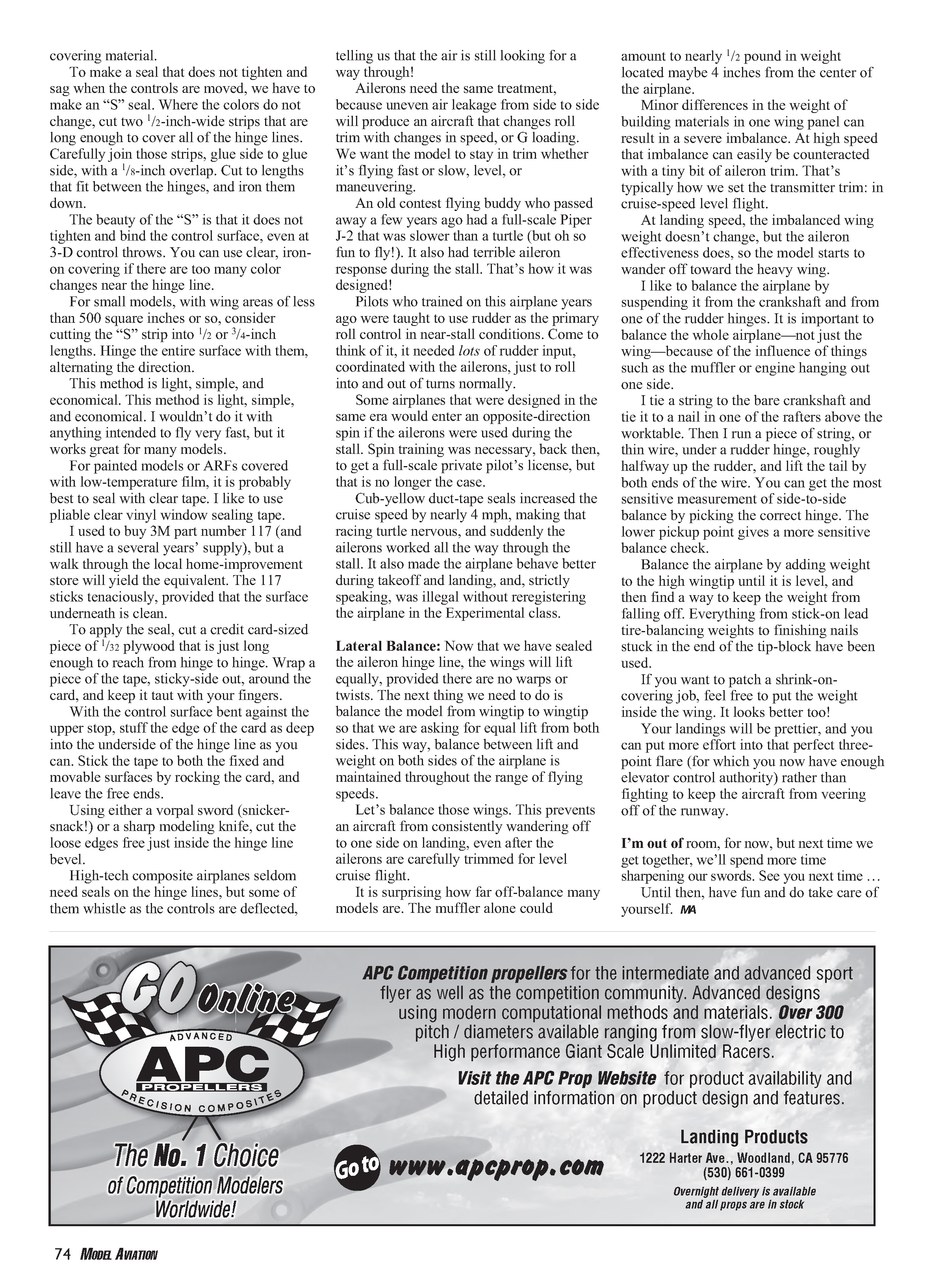
There are several ways to seal hinge gaps. Indoor models using Blenderm tape for hinges are already done. Planes using traditional figure-eight sewn or alternating S-type cloth hinges are also fine.
Many of us use iron-on plastic covering for at least the wings and tail feathers. Even with trim schemes that cut across hinge lines, we can do a pretty job using the same covering material.
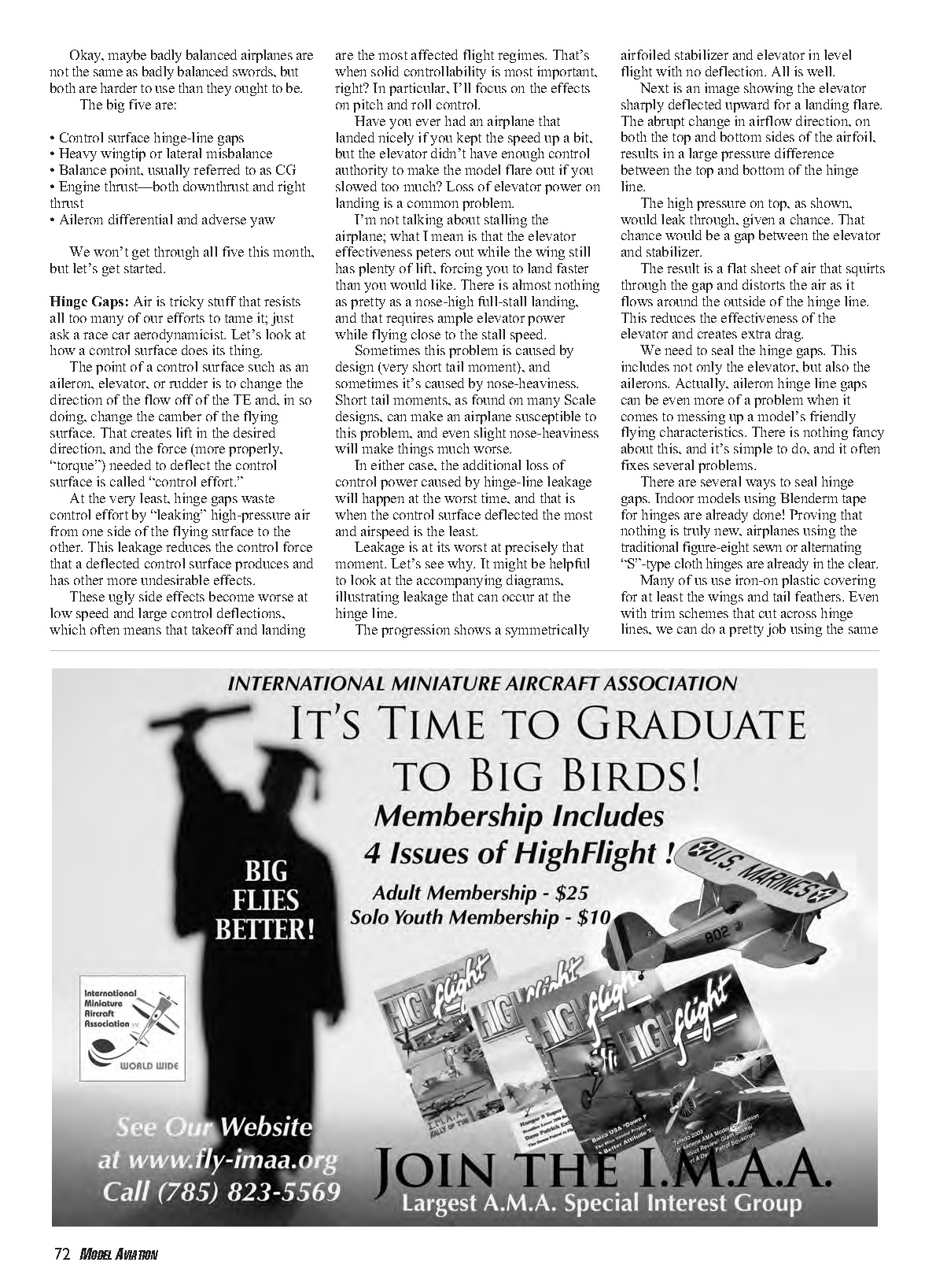
To make a seal that does not tighten and sag when the controls are moved, make an “S” seal. Where the colors do not change, cut two 1/2-inch-wide strips long enough to cover all of the hinge lines. Carefully join those strips, glue side to glue side, with a 1/8-inch overlap. Cut to lengths that fit between the hinges, and iron them down.
The beauty of the “S” is that it does not tighten and bind the control surface, even at 3-D control throws. You can use clear iron-on covering if there are too many color changes near the hinge line.
For small models, with wing areas of less than about 500 square inches, consider cutting the “S” strip into 1/2- or 3/4-inch lengths. Hinge the entire surface with them, alternating the direction.
This method is light, simple, and economical. I wouldn't do it with anything intended to fly very fast, but it works great for many models.
For painted models or ARFs covered with low-temperature film, it is probably best to seal with clear tape. I like to use pliable clear vinyl window-sealing tape.
I used to buy 3M part number 117 (and still have several years' supply), but a walk through the local home-improvement store will yield the equivalent. The 117 sticks tenaciously, provided the surface underneath is clean.
To apply the seal, cut a credit-card-sized piece of 1/32-inch plywood that is just long enough to reach from hinge to hinge. Wrap a piece of the tape, sticky-side out, around the card, and keep it taut with your fingers.
With the control surface bent against the upper stop, stuff the edge of the card as deep into the underside of the hinge line as you can. Stick the tape to both the fixed and movable surfaces by rocking the card, and leave the free ends.
Using a sharp modeling knife, cut the loose edges free just inside the hinge-line bevel.
High-tech composite airplanes seldom need seals on the hinge lines, but some of them whistle as the controls are deflected, telling us that the air is still looking for a way through.
Ailerons need the same treatment, because uneven air leakage from side to side will produce an aircraft that changes roll trim with changes in speed or G loading. We want the model to stay in trim whether it's flying fast or slow, level, or maneuvering.
An old contest flying buddy who passed away a few years ago had a full-scale Piper J-2 that was slower than a turtle (but oh so fun to fly!). It also had terrible aileron response during the stall—that's how it was designed.
Pilots who trained on this airplane years ago were taught to use rudder as the primary roll control in near-stall conditions. Come to think of it, it needed lots of rudder input, coordinated with the ailerons, just to roll into and out of turns normally.
Some airplanes designed in the same era would enter an opposite-direction spin if the ailerons were used during the stall. Spin training was necessary back then to get a full-scale private pilot's license, but that is no longer the case.
Cub-yellow duct-tape seals increased the cruise speed by nearly 4 mph, making that racing turtle nervous, and suddenly the ailerons worked all the way through the stall. It also made the airplane behave better during takeoff and landing; strictly speaking, it was illegal without reregistering the airplane in the Experimental class.
Lateral Balance
Now that we have sealed the aileron hinge line, the wings will lift equally, provided there are no warps or twists. The next thing we need to do is balance the model from wingtip to wingtip so that we are asking for equal lift from both sides. This way, balance between lift and weight on both sides of the airplane is maintained throughout the range of flying speeds.
Let's balance those wings. This prevents an aircraft from consistently wandering off to one side on landing, even after the ailerons are carefully trimmed for level cruise flight.
It is surprising how far off-balance many models are. The muffler alone could amount to nearly a half-pound in weight located maybe four inches from the center of the airplane.
Minor differences in the weight of building materials in one wing panel can result in a severe imbalance. At high speed that imbalance can easily be counteracted with a tiny bit of aileron trim. That's typically how we set the transmitter trim: in cruise-speed level flight.
At landing speed, the imbalanced wing weight doesn't change, but the aileron effectiveness does, so the model starts to wander off toward the heavy wing.
I like to balance the airplane by suspending it from the crankshaft and from one of the rudder hinges. It is important to balance the whole airplane—not just the wing—because of the influence of things such as the muffler or engine hanging out one side.
I tie a string to the bare crankshaft and tie it to a nail in one of the rafters above the worktable. Then I run a piece of string, or thin wire, under a rudder hinge, roughly halfway up the rudder, and lift the tail by both ends of the wire. You can get the most sensitive measurement of side-to-side balance by picking the correct hinge. The lower pickup point gives a more sensitive balance check.
Balance the airplane by adding weight to the high wingtip until it is level, and then find a way to keep the weight from falling off. Everything from stick-on lead tire-balancing weights to finishing nails stuck in the end of the tip-block has been used.
If you want to patch a shrink-on covering job, feel free to put the weight inside the wing. It looks better too.
Your landings will be prettier, and you can put more effort into that perfect three-point flare (for which you now have enough elevator control authority) rather than fighting to keep the aircraft from veering off the runway.
I'm out of room for now, but next time we get together, we'll spend more time sharpening our swords. See you next time.
Until then, have fun and do take care of yourself.
MA
Transcribed from original scans by AI. Minor OCR errors may remain.

