
IL-2 Stormovik - 2007/10
Overview
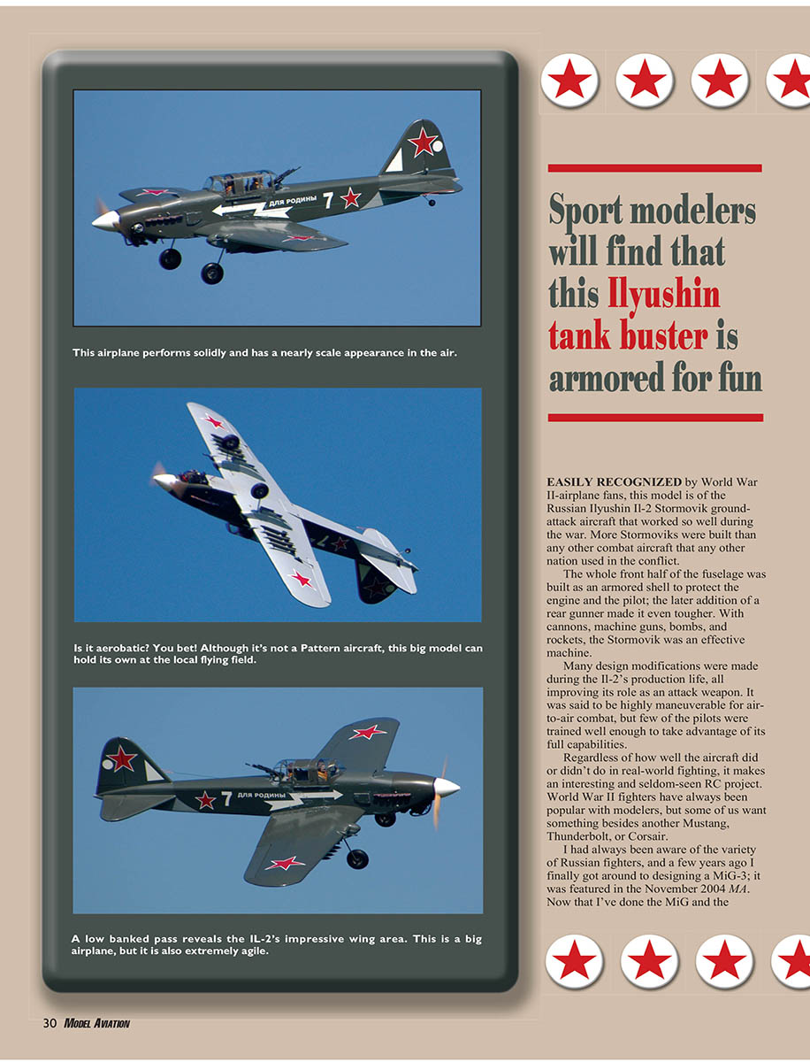
Easily recognized by World War II airplane fans, this model represents the Russian Ilyushin Il-2 Stormovik ground-attack aircraft that performed effectively during the war. More Il-2 Stormoviks were built than any other combat aircraft used by any nation in the conflict.
The whole front half of the fuselage was built as an armored shell to protect the engine and pilot; the later addition of a rear gunner made it even tougher. With cannons, machine guns, bombs, and rockets, the Stormovik was an effective combat machine.
Many design modifications were made during the Il-2's production life, all improving its role as an attack weapon. It was said to be highly maneuverable for air-to-air combat, but few pilots were trained well enough to take full advantage of its capabilities.
Regardless of real-world combat performance, the Il-2 makes an interesting and seldom-seen RC project. World War II fighters have always been popular with modelers, but some of us want something besides another Mustang, Thunderbolt, or Corsair.
I had always been aware of the variety of Russian fighters, and a few years ago I finally got around to designing a MiG-3; it was featured in the November 2004 MA. Now that I've done the MiG and the Stormovik, a future project may be one of the Soviet Yaks.
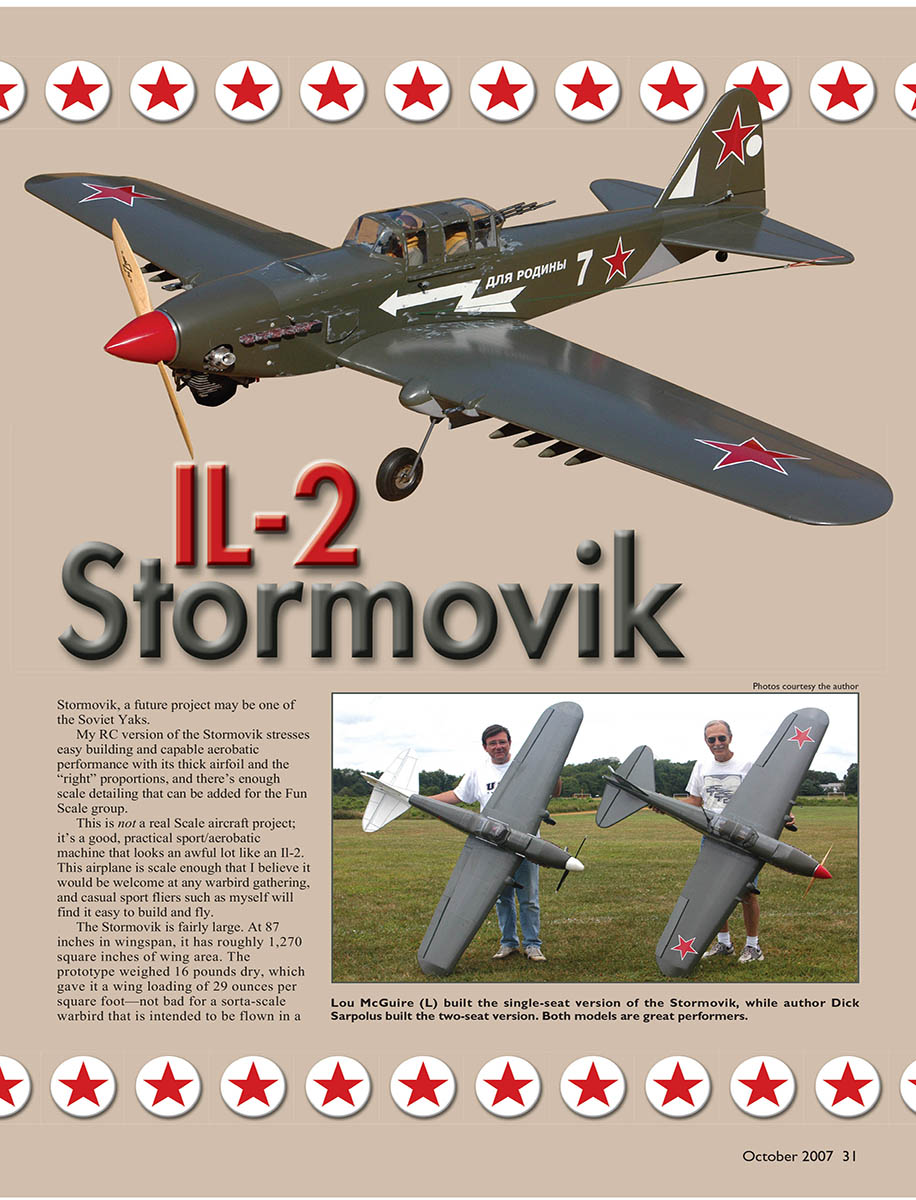
My RC version of the Stormovik stresses easy building and capable aerobatic performance with a thick airfoil and the right proportions, and there is enough scale detailing that can be added for Fun Scale events. This is not a strict scale project; it's a practical sport/aerobatic machine that looks a lot like an Il-2. The airplane is scale enough to be welcome at warbird gatherings, and casual sport fliers will find it fairly easy to build and fly.
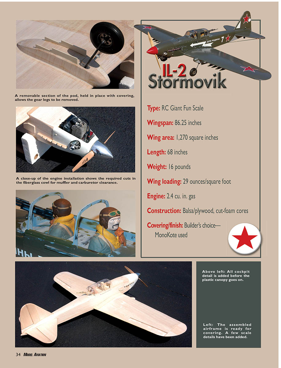
At about 86.25 inches wingspan, it has roughly 1,270 square inches of wing area. The prototype weighed 16 pounds dry, which gives it a wing loading of about 29 ounces per square foot—not bad for a sorta-scale warbird intended for lively and aerobatic flying.
I laid out the design around an engine in the 2.4 cu. in. gas range. From experience with other airplanes, I was confident those numbers would produce the kind of performance I wanted. There are many gas engines in this size range to choose from, or you could use a good-sized 1.8 or 2.1 cu. in. glow engine.
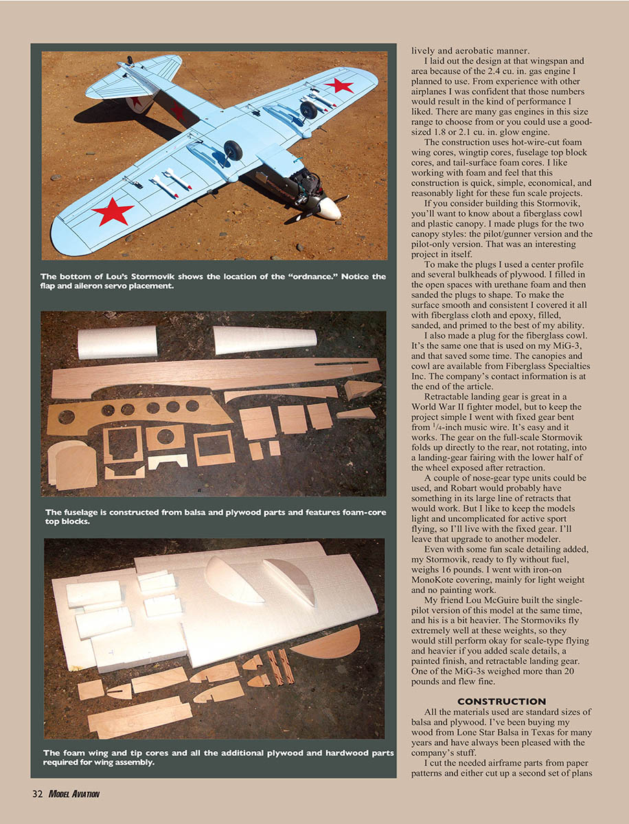
Construction uses hot-wire-cut foam wing cores, wingtip cores, fuselage top block cores, and tail-surface foam cores. I like working with foam and find this construction quick, simple, economical, and reasonably light for fun-scale projects.
If you build this Stormovik, expect to use a fiberglass cowl and a plastic canopy. I made plugs for two canopy styles: the pilot/gunner version and the pilot-only version. To make the plugs I used a center profile and several plywood bulkheads, filled the open spaces with urethane foam, sanded, then covered the plugs with fiberglass cloth and epoxy. I finished them by filling, sanding, and priming.
I also made a plug for a fiberglass cowl—the same one used on my MiG-3, which saved time. The canopies and cowl are available from Fiberglass Specialties Inc. (contact info at the end).
Retractable landing gear is great on a WWII fighter model, but to keep this project simple I used fixed gear bent from 1/4-inch music wire. It's easy and it works. The full-scale Stormovik's gear folds directly rearward into a fairing with the lower half of the wheel exposed; a modeler could install a couple of nose-gear-type units or a Robart retract set if desired. I chose to keep the model light and uncomplicated for active sport flying and left retracts as a possible upgrade for someone else.
Even with some fun-scale detailing, my Stormovik weighed 16 pounds ready to fly (without fuel). I used iron-on MonoKote covering for light weight and to avoid painting. My friend Lou McGuire built the single-pilot version at the same time; his is a bit heavier. The Stormoviks fly extremely well at these weights and would still perform acceptably if heavier for scale-type flying with added details, painted finishes, and retractable gear. One of my MiG-3s weighed more than 20 pounds and flew fine.
Specifications
- Type: RC Giant Fun Scale
- Wingspan: 86.25 inches
- Wing area: 1,270 square inches
- Length: 68 inches
- Weight: 16 pounds (prototype, dry)
- Wing loading: 29 ounces/square foot
- Engine: 2.4 cu. in. gas (also compatible with 1.8–2.1 cu. in. glow engines)
- Construction: Balsa/plywood, cut-foam cores
- Covering/finish: Builder's choice—MonoKote used
CONSTRUCTION
All materials used are standard sizes of balsa and plywood. I source wood from Lone Star Balsa and have been pleased with their stock.
I cut the needed airframe parts from paper patterns. I either cut up a second set of plans or trace the part outlines and cut the tracings. I draw around the patterns onto the balsa or plywood with a ballpoint pen and cut the parts with a band saw or scroll saw.
I cut the grooved hardwood landing-gear blocks with a small Dremel table saw and use a K&S heavy-duty wire bender to form the 1/4-inch wire landing-gear pieces.
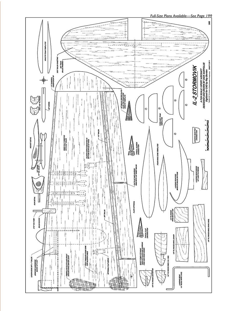
Template patterns for the foam-core parts are on the plans. I make templates from 3/32-inch plywood and cut the foam parts using a basic hot-wire box, nichrome wire, and a Variac power supply. If you're not set up for foam-core scratch building, someone in your club may cut the foam for you, or you can order the foam components from Robin's View Productions.
Wing
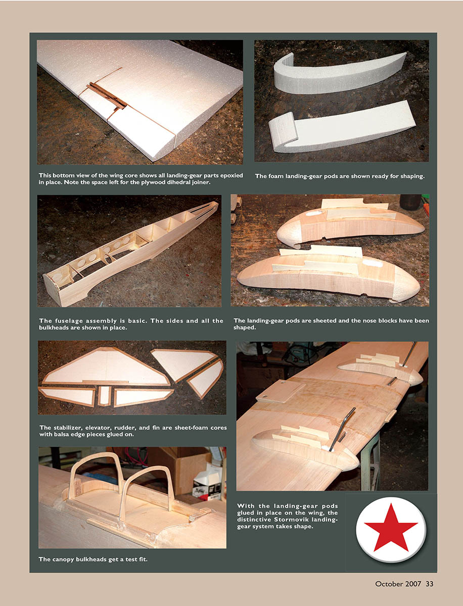
After building the two wing panels, cut them up to install the plywood landing-gear reinforcement pieces. Mark the cuts on the foam and slice them on a band saw or by hand with a hacksaw blade. Trim the foam pieces for the landing-gear blocks and epoxy everything back together: foam parts, plywood pieces, and landing-gear blocks.
Hardwood gear blocks should protrude 3/32 inch from the foam cores. Sheet the wing with 3/32-inch balsa, edge-glued to obtain the necessary width. I use 3- or 4-inch-wide balsa and aliphatic resin glue because it's easy to handle and sands to a smooth surface.
For the sheeting: after sanding the edges for a good fit, tape sheets together to get the width, flip the wood over, open the taped joint like a hinge over the workbench edge, and apply glue one joint at a time. With the wood flat, scrape excess glue from the joint with a putty knife and weight the wood until the glue dries. Remove the masking tape and use the taped side as the outer surface of the sheeting because it looks cleaner than the glued side. Block-sand the sheeting smooth before applying it to the foam cores.
I use Dave Brown Products Southern's Sorghum contact cement to bond balsa sheeting to foam cores because it works well. Other methods include thin epoxy or spray contact cement—test on scrap foam before using anything that might melt it.
Wingtips are made from foam cores, which is easier than carving solid balsa tips. Templates are provided for the upper and lower foam wingtip sections; glue them to the balsa centerpiece, sheet, and attach to the sheeted main wing panels.
Don't forget to burn or drill the holes through the foam cores for the aileron extension cables before joining the wing panels with the plywood dihedral joiner.
With the wing cores sheeted top and bottom, sand the leading edge square, glue on an oversize balsa LE strip, then plane and sand it to shape. Cut the slot through the LE for the plywood wing mounting tab, which is glued in place after the wing fits the fuselage saddle.
Wrap the center-section joint with heavy fiberglass cloth and epoxy, scraping excess adhesive off with a piece of cardboard and leaving enough to saturate the cloth. Cut the ailerons from the sheeted wing panels, trim them to allow for balsa edging, and sand them to shape. They are hinged along the centerline.
Flaps are easy to add if desired. I hinge flaps along their lower edge, allowing them to drop way down. Cut recesses in the wing's lower surface and epoxy in plywood mounts for the aileron and flap servos.
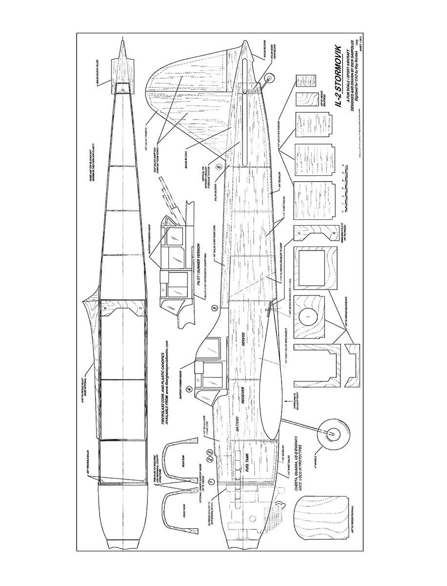
Fuselage
Use firm to hard balsa for the two fuselage sides, edge-gluing and splicing to get the required size. I used a hole saw to cut lightening holes in the plywood doublers. Glue on the plywood doublers, wing-saddle doublers, and lower rear edge strips to both fuselage sides.
I believe in a thick firewall, so I epoxy a piece of 1/8-inch and a piece of 1/4-inch plywood together. With one fuselage side flat on the workbench, epoxy the firewall and the next three plywood bulkheads perpendicular to that side. Glue the second side to those bulkheads; alignment is easy since the sides are parallel from the firewall to the wing TE position.
Use triangle stock behind the firewall to reinforce its joint with the fuselage sides and insert several small screws through the sides into the firewall. Add the plywood wing-bolt plate, then pull the tail end together and install the rear bulkheads. Fit the top foam blocks to the fuselage structure, sanding them if necessary so the top sheeting will be flush with the sides.
Use soft 1/8-inch balsa for the top sheeting, apply it to the foam blocks with contact cement, trim, and epoxy the top blocks in place. Do not add the bottom sheeting until the tail surface and tail-wheel pushrods have been installed.
Tail Surfaces and Final Assembly
Make tail surfaces on a flat workbench. Cut the flat sheet foam cores to shape, add balsa framing, apply balsa sheeting with contact cement, sand all edges to shape, and slot for hinges.
Align the wing to the fuselage, making sure the wing mounting tab fits well into the fuselage bulkhead when the wing is seated. Drill and tap the plywood wing mounting plate for the two 1/4-20 nylon bolts that hold the wing in place.
With the wing mounted, add the horizontal stabilizer and align it with the wing. Add the vertical fin, perpendicular to the stabilizer.
Recess control surfaces to accept 1/4-inch plywood mounting tabs for the nylon control horns on the ailerons, elevators, and rudder. Epoxy the plywood mounts in the surfaces and attach the nylon horns with self-tapping screws. I use 4-40 threaded rods and clevises for all linkages.
On this Stormovik I used fiberglass-tube pushrods from the two elevator servos to the two elevators. The pushrods are straight and cross over inside the fuselage; I shimmed one servo slightly higher than the other so the pushrods wouldn't rub.
I used separate composite flexible-tube pushrods for the rudder and tail-wheel steering linkages from the single rudder servo. An alternative is to have two rudder servos and run another flexible pushrod to the tailwheel. On the prototype I used the dual-pushrod arrangement only because the landing-gear mount was a bit in the way. The tail-wheel wire extends up through the fuselage with a bend going into the rudder; either method will work.
Make servo extension cables into a Y harness for the aileron servos in the wing, and another Y harness for the two elevator servos. The 1800 mAh battery pack is wrapped in foam and positioned behind the fuel tank along with the receiver.
The large K&S wire bender easily handles 1/4-inch wire to form the main landing-gear legs. Retain the gear in the grooved hardwood blocks with nylon straps and screws.
Shape landing-gear fairings from foam blocks, contact-cement balsa sheeting over them, and use a balsa block for the rounded nose section that extends ahead of the wing. Cut landing-gear doors from light plywood and glue the fairings to the wing panels. Small sections allowing installation of the wire gear are held in place with the iron-on covering material; these scraps are easy to remove for rebending the landing gear after hard landings.
One scale feature I didn't bother with was the wing-root fillets to the fuselage; they would be a nice addition but I was lazy.
I used a B&B Specialties 16-ounce fuel tank for the gas engine, mounted with plenty of foam around it behind the firewall. I have a plywood spacer pad behind the engine mount to provide room for the muffler ahead of the firewall. Whatever engine is used will have its own mounting arrangement.
The fiberglass cowl is cut for engine, muffler, and carburetor clearance. I mount the cowl by overlapping it on the fuselage and using #6-32 nylon bolts to retain it.
Trim the plastic canopy to fit and put plywood tabs in the fuselage so the canopy can be held in place with small screws on each side. Add balsa strips to the top fuselage sides in the canopy area for fit and alignment.
Install a balsa cockpit floor and glue pilot and gunner figures to the floor. Additional cockpit detail may be added. Gluing the canopy on and fairing it into the fuselage looks better for scale appearance, but I prefer a removable canopy for easy replacement after flip-over landings or other damage.
Mask off and spray-paint canopy framing and armor-plate areas. Thin plastic glued on would also add realism to those features.
Finish
I'm sold on using iron-on coverings for these fun-scale sport models. Lou and I applied MonoKote to our Stormoviks and sprayed the cowls and canopies with matching LustreKote paint.
Scale Details
- Squadron/Signal Publications' Il-2 Stormovik in Action (aircraft number 155) was extremely helpful for detailing.
- Although not a strict scale modeler, it was fun to make the rockets for underwing mounting, the machine guns and exhaust stacks, paint pilot and gunner figures, and do canopy detailing.
- The Russian lettering on the sides of my airplane reads (I hope) "For the Motherland," typical of slogans painted on Russian combat aircraft in WWII. Other markings were chosen for overall scale realism rather than strict authenticity.
I enjoy flying this model through all the aerobatic maneuvers I can handle; low inverted passes are especially fun. The goal is fun!
Dick Sarpolus [email protected]
Sources
- Fiberglass Specialties Inc.
15715 Ashmore Dr. Gilmore AK 72732 (479) 359-2429 www.fiberglassspecialtiesinc.com
- Lone Star Balsa
15 Industrial Lancaster TX 75134 (972) 218-9663 www.lonestar-models.com
- MonoKote/LustreKote: Great Planes Model Distributors
Box 9021 Champaign IL 61826 (217) 398-6300 www.top-flite.com
- Dave Brown Products
4560 Layhigh Rd. Hamilton OH 45013 (513) 738-1576 www.dbproducts.com
- K&S Engineering
6917 W. 59th St. Chicago IL 60638 (773) 586-8503 www.ksmetals.com
- B&B Specialties
14234 Cleveland Rd. Granger IN 46530 (574) 277-0499 www.bennettbuilt.com
Transcribed from original scans by AI. Minor OCR errors may remain.

