


Improve Your Approach
by Ben Lanterman
Stop yawing problems that occur during takeoff
My models seemed to have developed minds of their own, swerving and weaving all over the runway and often ending up in a ground loop. If you are a good enough pilot that you can fly an airplane down the runway centerline and perform a nice takeoff down the same line, with zero problems, in all conditions, you don't need to read this article. I wrote it for the rest of us.
I have seen fliers at Scale meets try to make good takeoffs but have problems with side winds, slippery runways, and nerves; they could have used help. Then there are those similar to me, who simply don't want to wreck an aircraft. I wanted a device that would help me with this issue with the flip of a switch.
Have you ever taken a beautiful new pride and joy—such as a Bf 109—out for its first flight, feeling great about its potential but trepidatious because you know that it has a bad reputation for takeoff handling? The full-scale airplane had a tendency to put its pilots in danger. Moderate crosswinds against the runway make things even worse.
You taxi the model downwind on the club's nice paved runway, turn upwind, and slowly apply power. As it picks up speed, the aircraft initially starts to yaw to its left. The problem worsens as the tail tries to come up. You expect this, so you keep applying power and right rudder.
But then the model hits a bump or encounters a gust of side wind, and it seems to go nuts. The gust goes away and the airplane's speed increases, and then things get hairy. It swerves to the right and again to the left, until it finally zigzags all over the runway, maybe even resulting in an excellent example of a ground loop. The wings get scraped and the propeller is missing chunks; it isn't fun.
After several more attempts, you succeed at a wobbly takeoff (which is probably cross-runway into the wind) and finally get a good flight going. After all, the model does fly well. One might wonder if all flights are going to start this way. The answer is no, but achieving consistent takeoffs and landings usually requires intensive practice with that aircraft or plain luck. Don't worry; there is another way.
The previous scenario is autobiographical. I have had many of those kinds of takeoffs with some of my Scale and sport models, and it seemed to happen all the time with a recently acquired Messerschmitt Bf 109.
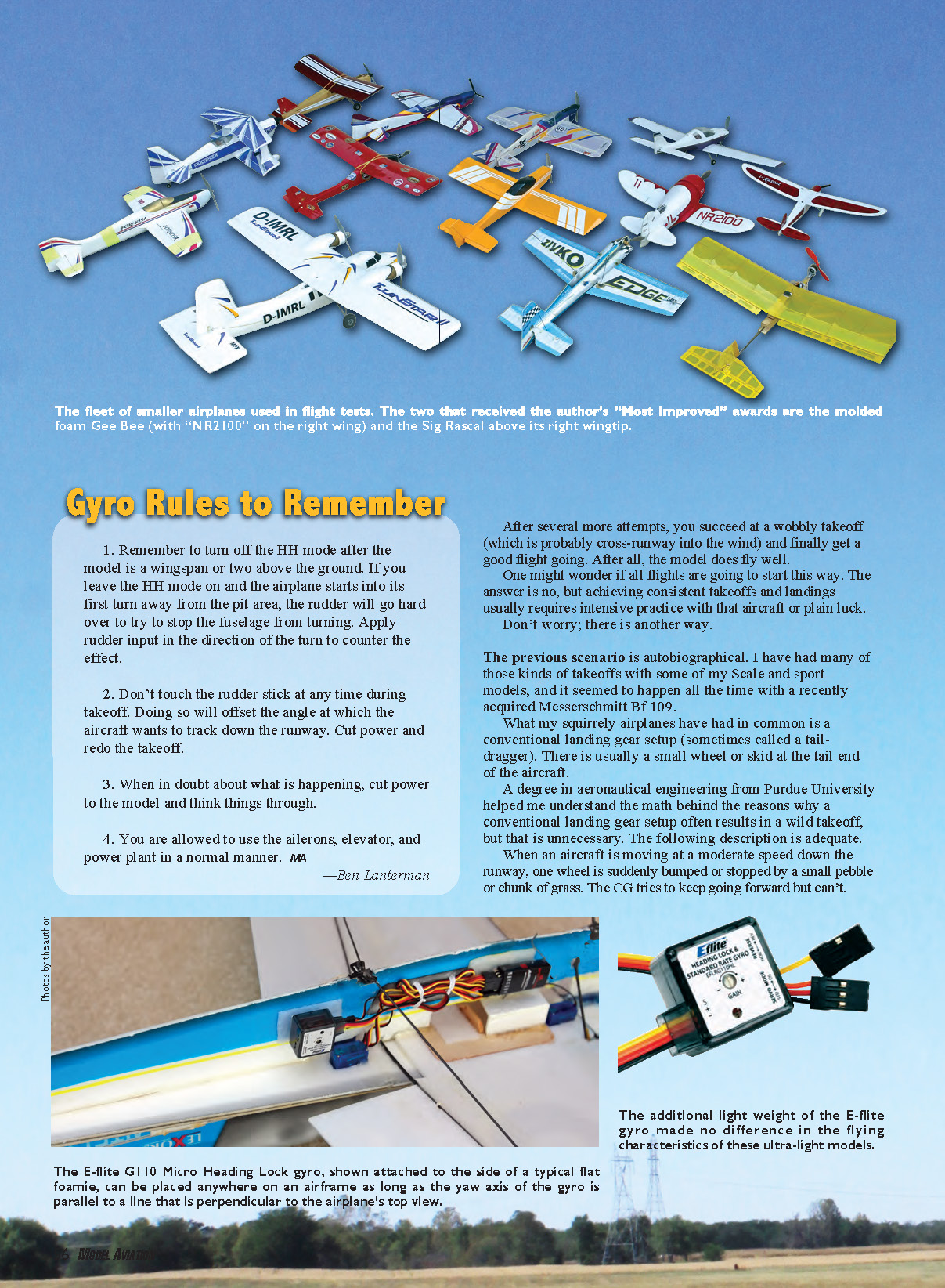
What my squirrely airplanes have had in common is a conventional landing gear setup (sometimes called a tail-dragger). There is usually a small wheel or skid at the tail end of the aircraft.
When an aircraft is moving at a moderate speed down the runway, one wheel is suddenly bumped or stopped by a small pebble or chunk of grass. The CG tries to keep going forward but can't. Forces from the propeller are there, and the stopped wheel causes the CG to deflect a bit to the side. Then the airplane rotates even more around the restrained wheel. Unless a tail wheel, a tail skid, or the vertical tail has enough side force to stop the rotation, the fuselage will continue to go around, to the point at which the CG will try to go along the original line of travel, even when the fuselage is sideways. Since the model is moving slowly, the vertical tail won't contribute enough aerodynamic stabilizing force to stop the turning. If the tail wheel is off of the ground, the situation is worse.
A tricycle landing gear setup doesn't suffer from this problem. The CG in front of the main wheels exerts a stabilizing force, and the nose wheel guides the fuselage. The worst thing an aircraft with tricycle gear typically does is go crooked when a gust of side wind hits it. However, such an airplane can have takeoff problems if the nose gear is set up to be too touchy.
If conditions around the model were smooth all the time and the tail wheel worked effectively against a side force, we wouldn't have a big problem. But any number of small things can trigger the divergence to the unstable yaw condition. However, the biggest factor for most of us is the massive gusting side wind that seems to come up when we find the rare spare hour or two to fly our models.
Gyro Rules to Remember
- Remember to turn off the HH (heading-hold) mode after the model is a wingspan or two above the ground. If you leave the HH mode on and the airplane starts into its first turn away from the pit area, the rudder will go hard over to try to stop the fuselage from turning. Apply rudder input in the direction of the turn to counter the effect.
- Don't touch the rudder stick at any time during takeoff. Doing so will offset the angle at which the aircraft wants to track down the runway. Cut power and redo the takeoff.
- When in doubt about what is happening, cut power to the model and think things through.
- You are allowed to use the ailerons, elevator, and power plant in a normal manner.
The Gyro
A Google search led me to an RC Universe forum thread concerning the use of gyros in models. Because these devices are mandatory in RC helicopters, there have been terrific advances in both affordability and capability. The consensus on the thread was that using a gyro on the yaw axis of an airplane could help.
Instructions that come with gyros do not recommend them for airplanes. I generally recommend following the manufacturer's directions, but using a gyro heading-hold (HH) mode for the specific purpose of aiding takeoff seems to work well.
The pilot must remember to turn off the gyro when the aircraft has obtained an altitude of 3–4 feet. At that time the flier takes control of the model.
You can use an all-solid-state gyro without knowing a thing about what is inside the little box. I think of the device as a tiny person who senses the airplane’s yawing motions during takeoff and instantly gives the rudder command needed to stop them. The gyro works exactly the way I try to—but a heck of a lot faster and more accurately than I can.
A modern gyro has two modes: rate damping (RD) and HH. The RD mode will diminish oscillations in yaw, but it won’t necessarily keep the aircraft on the runway. The HH mode is what we will use for the takeoff problem. We want our model to go straight down the runway with no corrective input from us.
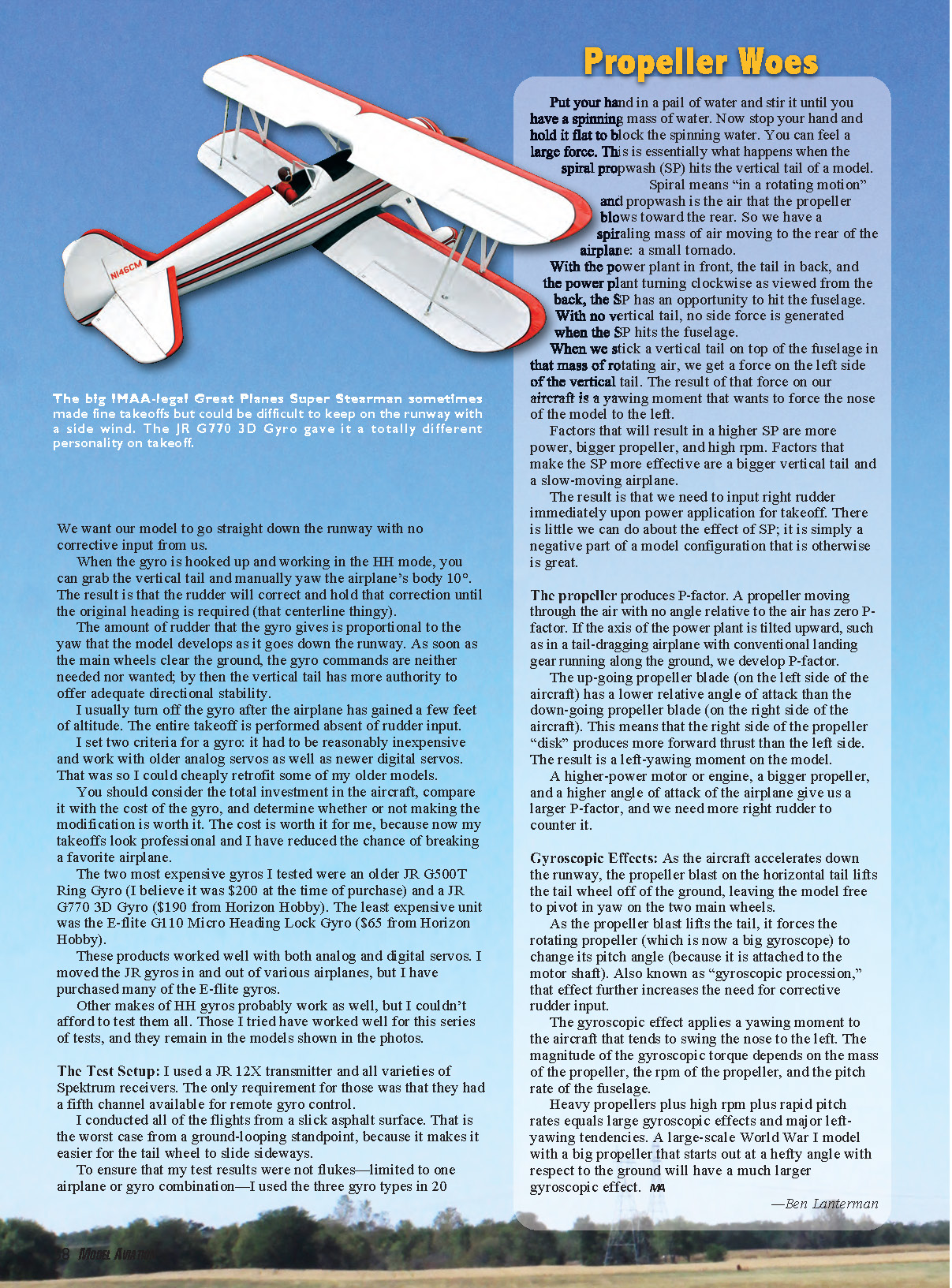
When the gyro is hooked up and working in the HH mode, you can grab the vertical tail and manually yaw the airplane’s body 10°. The result is that the rudder will correct and hold that correction until the original heading is required. The amount of rudder that the gyro gives is proportional to the yaw that the model develops as it goes down the runway. As soon as the main wheels clear the ground, the gyro commands are neither needed nor wanted; by then the vertical tail has more authority to offer adequate directional stability.
I usually turn off the gyro after the airplane has gained a few feet of altitude. The entire takeoff is performed absent of rudder input.
I set two criteria for a gyro: it had to be reasonably inexpensive and work with older analog servos as well as newer digital servos. That was so I could cheaply retrofit some of my older models. You should consider the total investment in the aircraft, compare it with the cost of the gyro, and determine whether or not making the modification is worth it. The cost is worth it for me, because now my takeoffs look professional and I have reduced the chance of breaking a favorite airplane.
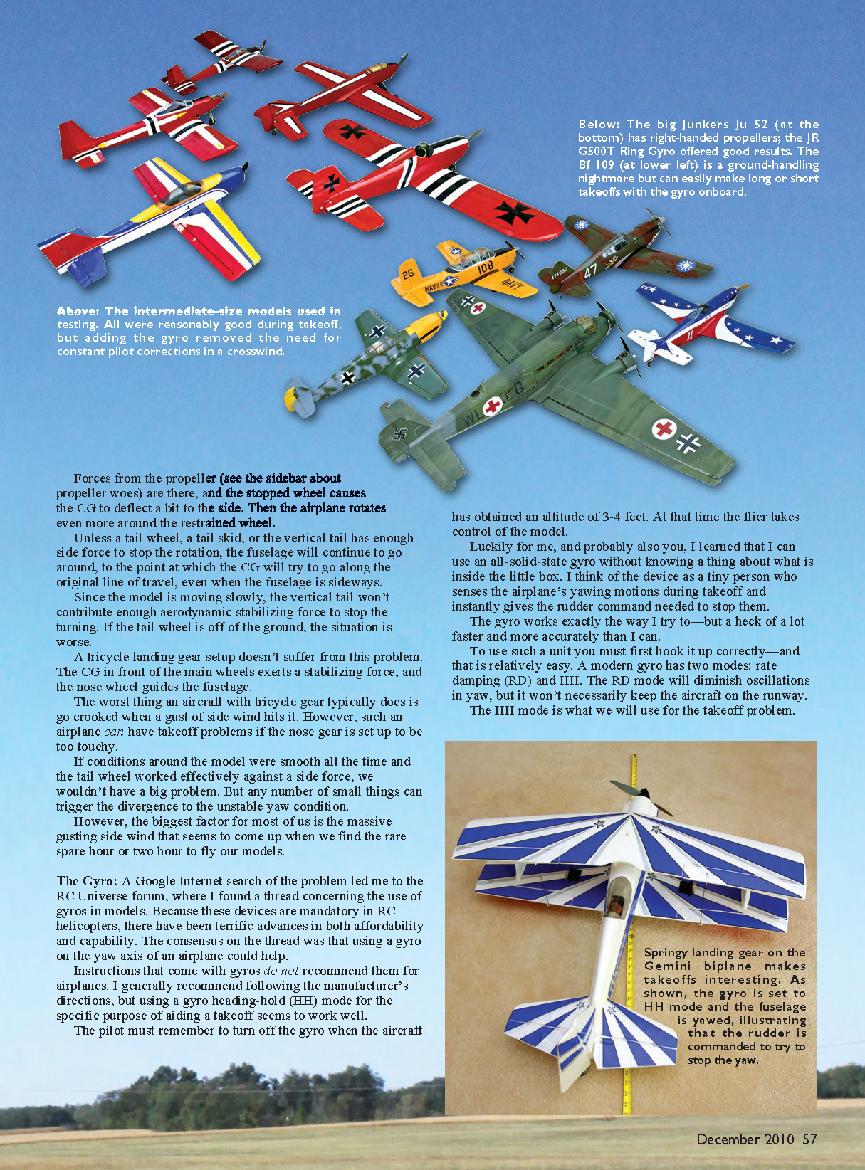
The two most expensive gyros I tested were an older JR G500T Ring Gyro (about $200 at time of purchase) and a JR G770 3D Gyro ($190 from Horizon Hobby). The least expensive unit was the E-flite G110 Micro Heading Lock Gyro ($65 from Horizon Hobby). These products worked well with both analog and digital servos. I moved the JR gyros in and out of various airplanes, but I have purchased many of the E-flite gyros. Other makes of HH gyros probably work as well, but I couldn’t afford to test them all.
The gyro is mounted in the aircraft so that the yaw axis of the device is parallel to the yaw axis of the model. The yaw axis of the airplane is a line that goes through its CG and is perpendicular to the model when it is held level. The gyro does not have to be positioned on the aircraft CG.
It does need to be mounted so that vibration from the engine or motor will not shake it apart. I recommend using Velcro to attach the gyro to a light-plywood base. Glue that base to a piece of thin foam, and use Velcro to attach the foam piece to the model. This provides double insulation from power-plant vibration and allows the gyro to be easily moved if necessary.
The gyro has two plugs that go to the receiver: one goes into the rudder channel and the other goes into Channel 5. The auxiliary channel switch is used to change the gyro from its HH mode to its RD mode (or off altogether). The rudder servo plugs directly into the gyro.
Following the instructions, the HH limit (gain) is set high (approximately 100%) and the RD gain is set extremely low (roughly 10%). Because the low RD gain effectively turns off the gyro, the transmitter auxiliary switch is used to turn the HH mode on and off. You will have to determine what works using your radio and gyro instructions.
Set the stick trim sliders to neutral and rudder subtrim values (if available) to zero. Use rudder pushrod adjustments to mechanically zero the rudder position. Make sure that the rudder operates freely and correctly.
To make initial settings for the gyro gain:
- Turn on the transmitter with the auxiliary switch set to the gyro RD mode position.
- Turn on the receiver and gyro, letting the model remain still for 15–20 seconds to let the gyro initialize.
- Switch on the gyro HH mode. You might see the rudder drift slightly or drive to the extremes of throw.
- Switch back to RD mode and use the rudder stick trim sliders to adjust the rudder drift direction to be opposite of the observed drift.
- Switch back to HH and observe the rudder action. Repeat until you get a nice zero-drift setting in HH mode.
- Switch back to RD mode and check the mechanical zero, adjusting pushrods if necessary.
Now determine the direction of the gyro correction. In HH mode, if you yaw the airplane to the left, the rudder should be driven to the right as it responds to the yaw. If the rudder deflection is going the wrong way, use the small switch on the side of the gyro to reverse it. If the rudder-angle change is equal to or more than the applied yaw angle, the aircraft is in a good starting place. Exact angular response can be fine-tuned later, but it is noncritical.
Propeller Woes
Put your hand in a pail of water and stir it until you have a spinning mass of water. Now stop your hand and hold it flat to block the spinning water. You can feel a large force. This is essentially what happens when the spiral propwash (SP) hits the vertical tail of a model.
Spiral means “in a rotating motion” and propwash is the air that the propeller blows toward the rear. So we have a spiraling mass of air moving to the rear of the airplane: a small tornado.
With the power plant in front, the tail in back, and the power plant turning clockwise as viewed from the back, the SP has an opportunity to hit the fuselage. With no vertical tail, no side force is generated when the SP hits the fuselage. When we stick a vertical tail on top of the fuselage in that mass of rotating air, we get a force on the left side of the vertical tail. The result is a yawing moment that wants to force the nose of the model to the left.
Factors that will result in a higher SP are more power, bigger propeller, and high rpm. Factors that make the SP more effective are a bigger vertical tail and a slow-moving airplane. The result is that we need to input right rudder immediately upon power application for takeoff. There is little we can do about the effect of SP; it is simply a negative part of a model configuration that is otherwise great.
P-factor: A propeller moving through the air with no angle relative to the air has zero P-factor. If the axis of the power plant is tilted upward, such as in a tail-dragging airplane with conventional landing gear running along the ground, we develop P-factor. The up-going propeller blade (on the left side of the aircraft) has a lower relative angle of attack than the down-going propeller blade (on the right side of the aircraft). This means that the right side of the propeller “disk” produces more forward thrust than the left side. The result is a left-yawing moment on the model.
A higher-power motor or engine, a bigger propeller, and a higher angle of attack of the airplane give us a larger P-factor, and we need more right rudder to counter it.
Gyroscopic effects: As the aircraft accelerates down the runway, the propeller blast on the horizontal tail lifts the tail wheel off the ground, leaving the model free to pivot in yaw on the two main wheels. As the propeller blast lifts the tail, it forces the rotating propeller (which is now a big gyroscope) to change its pitch angle because it is attached to the motor shaft. Also known as gyroscopic precession, that effect further increases the need for corrective rudder input.
The gyroscopic effect applies a yawing moment to the aircraft that tends to swing the nose to the left. The magnitude of the gyroscopic torque depends on the mass of the propeller, the rpm of the propeller, and the pitch rate of the fuselage. Heavy propellers plus high rpm plus rapid pitch rates equals large gyroscopic effects and major left-yawing tendencies.
Flight Testing
I used a JR 12X transmitter and various Spektrum receivers. The only requirement was that they had a fifth channel available for remote gyro control. I conducted all of the flights from a slick asphalt surface—that is the worst case from a ground-looping standpoint, because it makes it easier for the tail wheel to slide sideways.
To ensure my test results were not flukes—limited to one airplane or gyro combination—I used the three gyro types in 20 attempts. In preflight setups, the only practical difference I found was that the more expensive JR versions were stable with respect to keeping settings from day to day. I haven't had to adjust anything since the first setup. The E-flite gyro is much more inexpensive, and with that apparently comes a small amount of positional instability from day to day.
The practical meaning of that is: before each flight I check to ensure that the rudder holds neutral position when the gyro is switched to HH. If the rudder starts moving slowly when set to HH, it can be adjusted with a click or two of rudder trim. I have made the HH drift check part of my normal preflight checklist, so it is not a big problem. I like the E-flite gyro so well that I have 18 airplanes with one in each.
My initial taxi-only trials involved using small park flyers in a corner of an empty parking lot on a day with wind gusts up to 18 mph. I made taxi runs with full crosswind available, giving each airplane a bit of power and allowing it to run roughly 150 feet with the tail always on the ground. I did that with the gyro on and off. It was interesting to watch the rudder work to counter the wind gusts. A model that normally would have been blown all over the parking lot was following straight lines.
I moved the next tests out to the Boeing's Phantom Flyers field in Saint Charles, Missouri. The club has a good asphalt runway with a white stripe down the center. During the corn-growing season, when the wind is from the north, a terrific rotor is caused by the wind spilling over the corn. It hits the runway area as a rotating crosswind.
We flew aircraft after aircraft with consistent results, regardless of wind direction or airplane configuration, exercising variables such as P-factor, spiral propwash, gyroscopic effects, tire spacing, etc. Both slow and fast takeoffs were made to try to mess up the "gyro on" takeoffs, and none did. The device in HH mode consistently guided the models to make good takeoffs. Some airplanes took off straight but with evident oscillations, some were straight but moved sideways a bit as the wind blew them, and other takeoffs were straight. The results were uniformly positive with the HH gyros I tested.
A great thing about using a gyro is that if the nose gear is set incorrectly, the tail wheel is bent, or a landing gear part gets bent on a bad landing to the point where the aircraft would normally veer off to the side during takeoff, the device can still adjust the takeoff. The model will be directed to take off straight down the runway, although the body might have an apparent yaw angle.
The only exceptions were light models in a hard side wind. The fuselage would point down the runway and try to be parallel to the centerline, but the hard side wind would blow the whole airplane sideways. Still, this was better than the ground loop that normally took place.
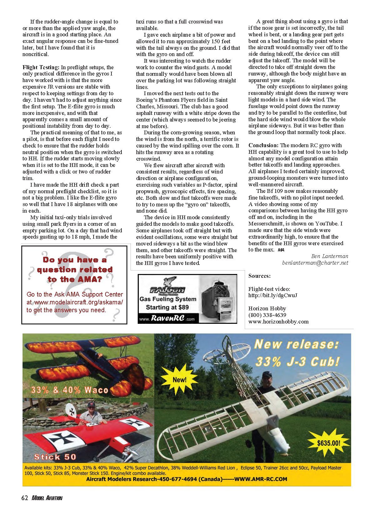
The models I used ranged from a light foam indoor aerobatic model (flown outside in the wind), to a large Junkers Ju 52 (94-inch span, 15-pound flying weight), to the huge Great Planes Super Stearman.
Conclusion
The modern RC gyro with HH capability is a great tool to help almost any model configuration attain better takeoffs and landing approaches. All airplanes I tested certainly improved; ground-looping monsters were turned into well-mannered aircraft. The Bf 109 now makes reasonably fine takeoffs, with no pilot rudder input needed. I made a video comparing HH gyro off and on (including the Messerschmitt) with very high side winds to exercise the benefits of HH gyros to the max.
Ben Lanterman [email protected]
Sources:
Flight-test video: http://bit.ly/dgCwuJ
Horizon Hobby (800) 338-4639 www.horizonhobby.com
Transcribed from original scans by AI. Minor OCR errors may remain.

