
INDY 400
by Scott Black
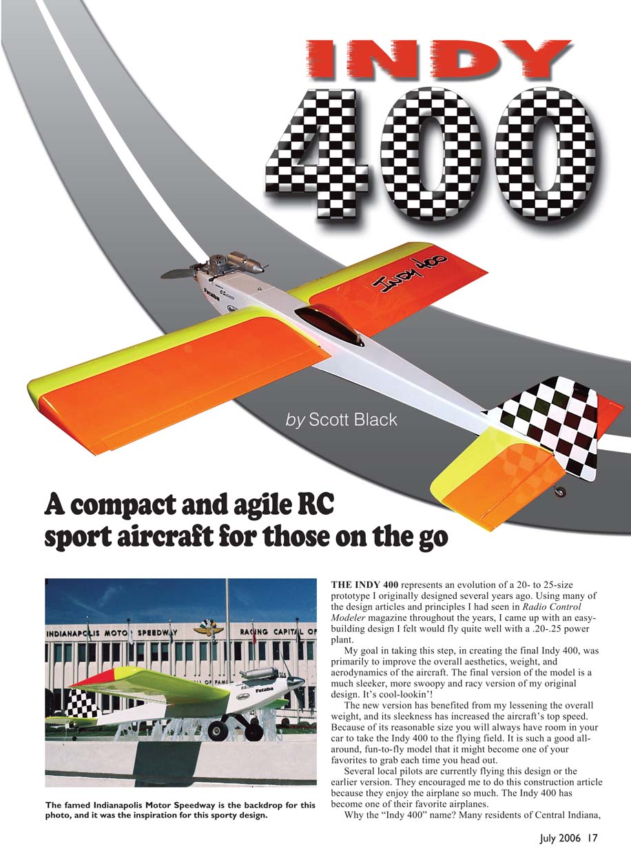
A compact and agile RC sport aircraft for those on the go
The Indy 400 represents an evolution of a 20- to 25-size prototype I originally designed several years ago. Using many of the design articles and principles I had seen in Radio Control Modeler magazine over the years, I came up with an easy-building design I felt would fly quite well with a .20–.25 power plant.
My goal in creating the final Indy 400 was primarily to improve the overall aesthetics, weight, and aerodynamics of the airplane. The final version is a much sleeker, more swoopy and racy evolution of my original design. The new version benefits from reduced weight and increased sleekness, which raises the aircraft’s top speed. Because of its reasonable size, you will always have room in your car to take the Indy 400 to the flying field. It is such a good all-around, fun-to-fly model that it might become one of your favorites to grab each time you head out.
Several local pilots currently fly this design or the earlier version and encouraged me to write this construction article because they enjoy the airplane so much. The Indy 400 has become one of their favorite airplanes.
Why the "Indy 400" name? Many residents of Central Indiana get Indianapolis 500 "race fever" each year. The Indy 400 name was inspired by the speed, excitement, and color that surround this auto-racing event, and by the fact that the design has nearly 400 square inches of wing area. When I start this airplane at the flying field, sometimes I swear I can hear a voice in the distance say, "Gentlemen, start your engines!"
The Indy 400 was designed to do several things. First, it was a great way to pass lunch hours at work—creating the design became a mental escape for me. Second, I wanted a small airplane that did not act like a "little" airplane. This model handles very well: it flies like it is on rails, even in windy conditions. It is aerobatic yet easy to take off and land. After you are comfortable with the Indy 400, control responses can be set to higher throws and the airplane becomes a real sight to watch. Third, I wanted to keep the airplane inexpensive. There are many strong .25-size engines for reasonable money; on this model I chose an O.S. .25 FX and liked its rear-mounted needle valve and reputation for reliability.
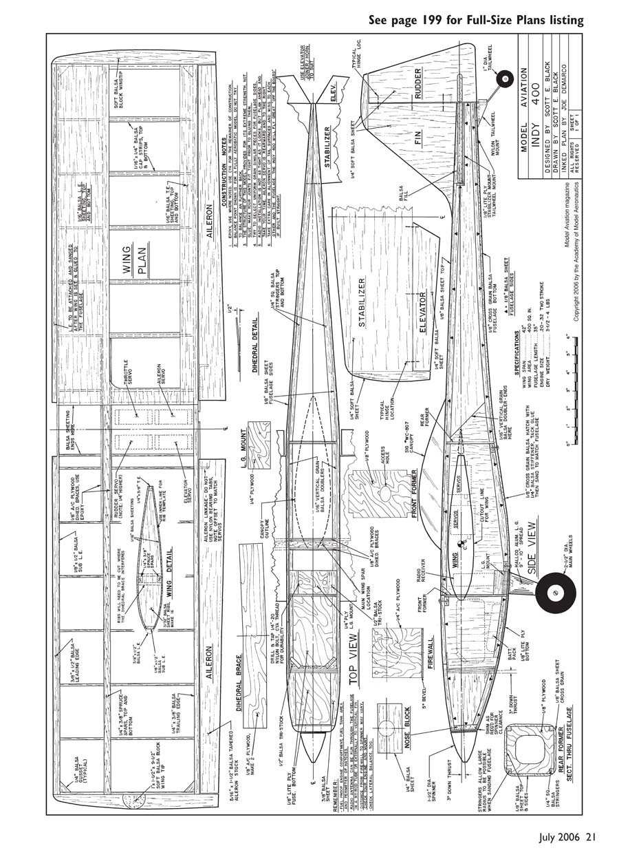
The interior of the Indy 400 was designed around standard-size servos and a flat 500 mAh battery pack. There is essentially one way to install the radio gear since the airplane is designed around it, but installation is straightforward if you follow the plans. Servos can be installed in a 2 x 2 arrangement or a 3 x 1 arrangement, as I did on the prototype.
Construction
A materials list of the balsa, plywood, and spruce items you will need is included on the plans. If you’ve saved odd-size sheets, drops, and scraps from other scratch-building projects and kits, dig through your stash first—many parts for the Indy 400 are small and can be cut from leftover stock. For example, the wing ribs can be light 1/8" stock; they don't all have to be 3/32".
The best approach to scratch building is to make a "kit" of all potentially precut parts before you start. Accuracy is crucial—make each piece as perfect as you can before moving to the next. If you buy balsa from a hobby shop, avoid pieces that are heavy and hard ("petrified balsa"). Mail-order suppliers generally have good-quality wood; when in doubt I overbuy a little so I don’t run out mid-build.
For part patterns, photocopy the plans and be aware some copiers reduce by 1–2%. Transfer patterns to wood by tracing with carbon paper, making dotted lines with push pins, or using a heat transfer (iron the photocopy toner onto the wood; remember you will be making a reverse image). All ribs are the same size—if you have a band saw or a jigsaw with a perpendicular blade you can cut ribs stacked, but if your tool wobbles make a master plywood template, harden the edges with cyanoacrylate, pin the ribs together, and lightly sand them true.
Make sure all spar notches line up perfectly and that your building surface is flat. The Indy 400 wing is very strong even before covering, and it would be difficult to remove a warp later. Building from scratch only adds a little time to the project and provides the satisfaction of saying, "I built it from scratch."
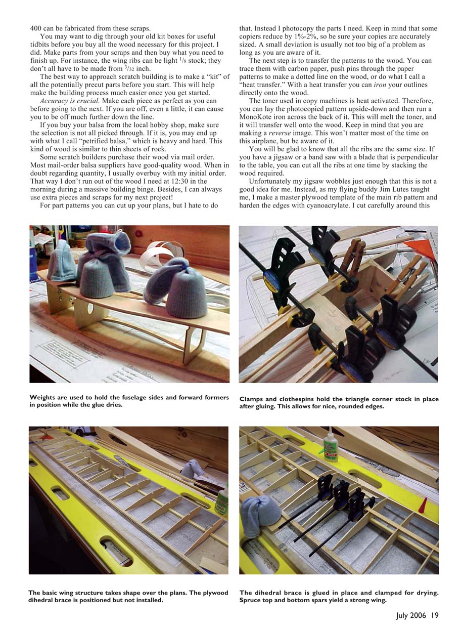
Wing
- Place waxed paper over the wing plans.
- Pin down the bottom 1/4" x 3/8" spruce main spar to the plans. The rear strip is oriented horizontally like the main spruce spar.
- Carefully align and glue all ribs (except the two center ribs) so each is 90° perpendicular to the building table.
- Add the rear 1/4" x 3/8" balsa strip, supporting it off the table (3/8" scrap works well). Add the 1/8" x 1/2" front secondary leading edge (LE); the real leading edge is attached after the wing is installed and glued in the fuselage—see the plans for the two-step process.
- The center ribs (two on each panel) are cut and attached after the dihedral braces are installed and the wing panels are joined.
- Shear webs are not required because of the beefy spruce spars; you could use balsa spars with shear webs if preferred.
- Use good-grade plywood for the dihedral braces. Join panels with 15- or 30-minute epoxy, making sure the panels are aligned and the dihedral matches the plans. The dihedral here is primarily for aesthetics (a slight dihedral cures the drooping look of a flat wing).
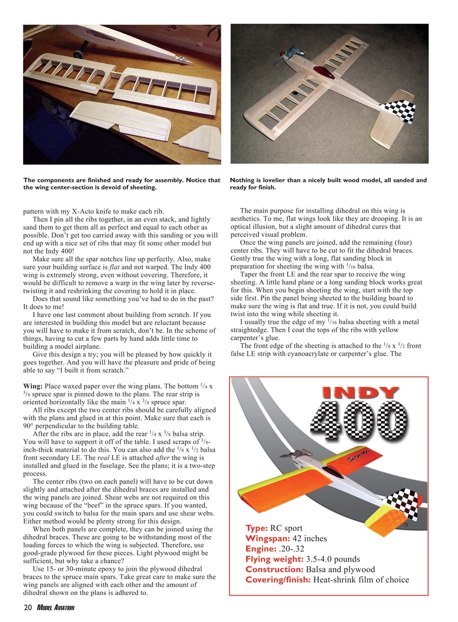
- After joining, add the remaining center ribs, then true the wing with a long flat sanding block in preparation for sheeting with 1/16" balsa.
- Taper the front LE and rear spar to receive sheeting. Start sheeting the top first, pinning the panel to the board to avoid building in a twist. True the edge of 1/16" sheeting with a metal straightedge and coat rib tops with yellow carpenter’s glue. Attach the front edge of the sheeting to the 1/8" x 1/2" front false LE with cyanoacrylate or carpenter’s glue.
- Glass Plus or Windex sprayed onto the sheeting helps it bend without cracking; attach the rear of the sheet to ribs with thin cyanoacrylate. Add capstrips when sheeting is complete.
- When the top is done, remove the wing and sheet the bottom similarly. Pin the wing again if possible to prevent warps. Add final capstrips and limited center-section sheeting—the center-section does not cover the wing inside the fuselage to allow radio installation.
- Wingtips are optional—plans show a style I like and are easy to make. Curved antivortex tips are another attractive option. Use fairly light wood or hollow the tips to avoid excess weight.
- The ailerons are conventional but the torque rods are installed off-center to match the aileron-servo locations. Do not install the aileron torque rods until the wing is permanently mounted.
- I chose to permanently mount the wing rather than make it removable; the model still fits small cars and trucks. I crashed my first prototype in a nose-first impact (battery failure)—repairs were no harder than if the wing had been bolted on.
Specifications
- Type: RC sport
- Wingspan: 42 inches
- Engine: .20–.32
- Flying weight: 3.5–4.0 pounds
- Construction: Balsa and plywood
- Covering/finish: Heat-shrink film of choice
Stabilizer and Fin
The tail feathers are straightforward. I made mine from 1/4" stock—choose fairly light balsa. The tail can be built up and sheeted or built as plank pieces. There is room for Robart-type hinges or cyanoacrylate hinges—use your preference.
The trickiest part is the small fairing pieces forming the fillet between the fin, stabilizer, and fuselage. I made a small T-shaped part from scrap 1/4" stock, tack-glued it in place, tack-glued two blank fillet pieces to the T, carved and sanded the fillets to match the fuselage, and then separated the pieces to produce two perfectly shaped fairings ready to glue in once the stabilizer and fin were permanently attached.
The tail-wheel assembly I used was the Du-Bro unit for 40-size models—it fit the bottom of the fuselage perfectly. Where the tail-wheel wire goes into the rudder, drill and then cyanoacrylate the hole (thin CA) to toughen that area. The control horn sandwiches the wire between the two control-horn assembly screws.
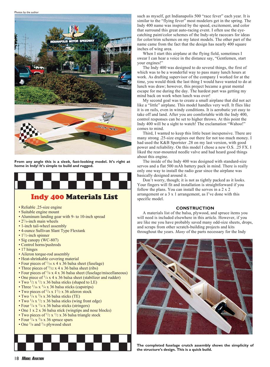
Fuselage
Try to find two pieces of lightweight 1/8" balsa with similar grain so the halves flex alike. Butt the two sides together and cement the seam with 1/8" x 1/4" balsa sheeting on the inside of the fuselage. Keep the glue joint away from servo bays and the power installation. When sheeting the fuselage sides, make sure edges match the top and bottom longerons; sand as necessary for a snug fit. Carve or sand the fillet shape into the back of the fuselage where the stabilizer will rest.
- The firewall is 1/8" birch plywood cut to fit the fuselage nose. Scarf the forward longerons into the firewall and glue them in place. Install the engine mount per the engine manufacturer's instructions—my O.S. .25 FX bolted to a standard mount with a spacer block for prop clearance.
- Build the fuselage on its side, ensuring each former is square and perpendicular. Notice the vertical 1/16" sheeting stops at the back of the engine mounting firewall. Build over the plans to ensure everything is straight.
- Make a template from the plans for the fuselage side, trace, score, and cut. Use the first side as a template for the second and sand both while pinned together for an exact match. Wait to cut through for the wing cutout until after the 1/16" balsa doubler is added for a cleaner cut.
- Install the landing-gear block and triangle stock as shown—strength is needed here. Drill and tap the mounting holes for the landing gear after the fuselage is completed.
- Fuselage stringers are vital: they add strength for minimal weight and allow you to round the fuselage during final sanding. After installing the stringers, bring the sides together at the rear and join them; slice an angled cut off each lower stringer (see plans) so they meet properly.
- Lay the fuselage on its side and measure up from the table to find the centerline, then flip and measure again to verify straightness. Use a good eyeball check as well.
- Add the three spruce crossbraces shown for attaching the upper fuel hatch and lower radio hatch (plywood is an acceptable substitute). I cyanoacrylate-glued the threaded holes after making them to strengthen the mounts.
- Construct a framework for the lower radio hatch from 1/8" balsa with a slight curve so an oversized hatch piece will follow the fuselage contour. Install the sheeting cross-grained.
- Add soft balsa blocks in the engine-mount area as needed for your engine and intended rounding in final sanding. I chose an O.S. .25 FX, which required accommodating the rear-mounted needle valve—take time to make a tidy engine installation.
- Top sheeting is straightforward—pick a light piece, attach, trim, and sand even with the fuselage sides. Add the plywood tail-wheel mount and plywood stabilizer-mount pieces; install the stabilizer mount level with the fuselage top, sighting from the rear to ensure parallel surfaces.
- Bottom sheeting is applied cross-grain for torsional strength. The front can be light plywood or cross-grain balsa as you prefer.
- Slide the wing into the fuselage to check fit; carefully enlarge the opening if it binds until the wing fits centered. Pin the stabilizer and check alignment—straight construction improves flight performance. Use a framing square to ensure the wing is 90° to the fuselage and adjust the cutout as needed for a true fit.
Radio installation
The radio compartment is a tight fit, but there is plenty of room if you arrange servos as shown on the plans. You can use regular-size radio gear. Lay out components as shown for a neat installation.
- The servo bays are made with 1/8" plywood doublers under the sheeting. I used standard-size servos in a 3 x 1 arrangement.
- Use the pushrod locations shown on the plans. Mount the receiver where the antenna can run along the top of the fuselage. The battery pack fits nicely under the wing center-section (I used a standard flat-pack battery wrapped in a plastic bag and placed it under the fuel tank).
- Notice the rudder servo is mounted higher than the elevator servo—this was achieved by adding another piece of spruce servo rail on top of the first to provide clearance.
- Note the offset aileron torque rods—this indicates which servo goes in which location.
- Drill the engine-mount and landing gear holes and install blind nuts now while access is easy.
Final Details
The canopy shown looks great but is not mandatory—you could choose another or none at all. Metal landing gear mounts are straightforward; you can use a premade unit or save weight and make gear from carbon fiber or fiberglass.
I highly recommend a tail wheel—only a skid limits ground control. If you fly from pavement, a tail wheel is a must.
Covering
I used UltraCote on the model pictured, but any film covering will work—the structure does not rely on covering for strength. Have fun with color: I used neon on the wings for visibility at dusk. In my experience UltraCote neon fades least, though all branding may fade a bit over time.
The checkerboard tail is a signature look—cover the rudder and fin with white, rule a 1" grid with a fine-tip grease pencil, then apply black squares of trim sheet. The grease pencil washes off with window cleaner. Racing stickers fit the Indy theme—make sure they are fuelproof.
For the "Indy 400" logo I enlarged the plans artwork to 10.5" long, cut letters from black MonoKote trim sheet, lifted the letters with masking tape, applied them to white MonoKote trim leaving about 1/8" white border, lifted the composite logo with masking tape, and applied it to the wing. This method works well.
Flying
Balance the aircraft. My example required a little tail weight with the O.S. .25 FX. If possible, locate the battery next to the receiver instead of under the fuel tank to avoid adding lead weight.
If the landing gear is set up correctly, taxiing is simple. Expect a slight left pull with throttle advance, and the Indy 400 will get up and go quickly.
The airplane is quite aerobatic for its size—it's not a 3-D machine, but it will likely become a favorite at the field. Sport .25 designs are less common now, but many modelers already have a .25-size engine or can buy one inexpensively. Combine modest fuel consumption with the flying fun, and you can't go wrong.
Have fun building and flying the Indy 400.
Scott Black [email protected]
Transcribed from original scans by AI. Minor OCR errors may remain.

