

Inside the Electronic Speed Control
by Lee Estingoy
Mysterious events are often attributed to mystical causes, and brushless power systems are about as mysterious as things get in RC. Some systems work and others don't. Why?
The usual explanation is something along the lines of, "It's a mystery!" The reason for a component failure is a mystery to most involved, but understanding a bit more about brushless systems can go a long way toward helping a hobbyist enjoy outstanding reliability in an electric-powered airplane or helicopter.
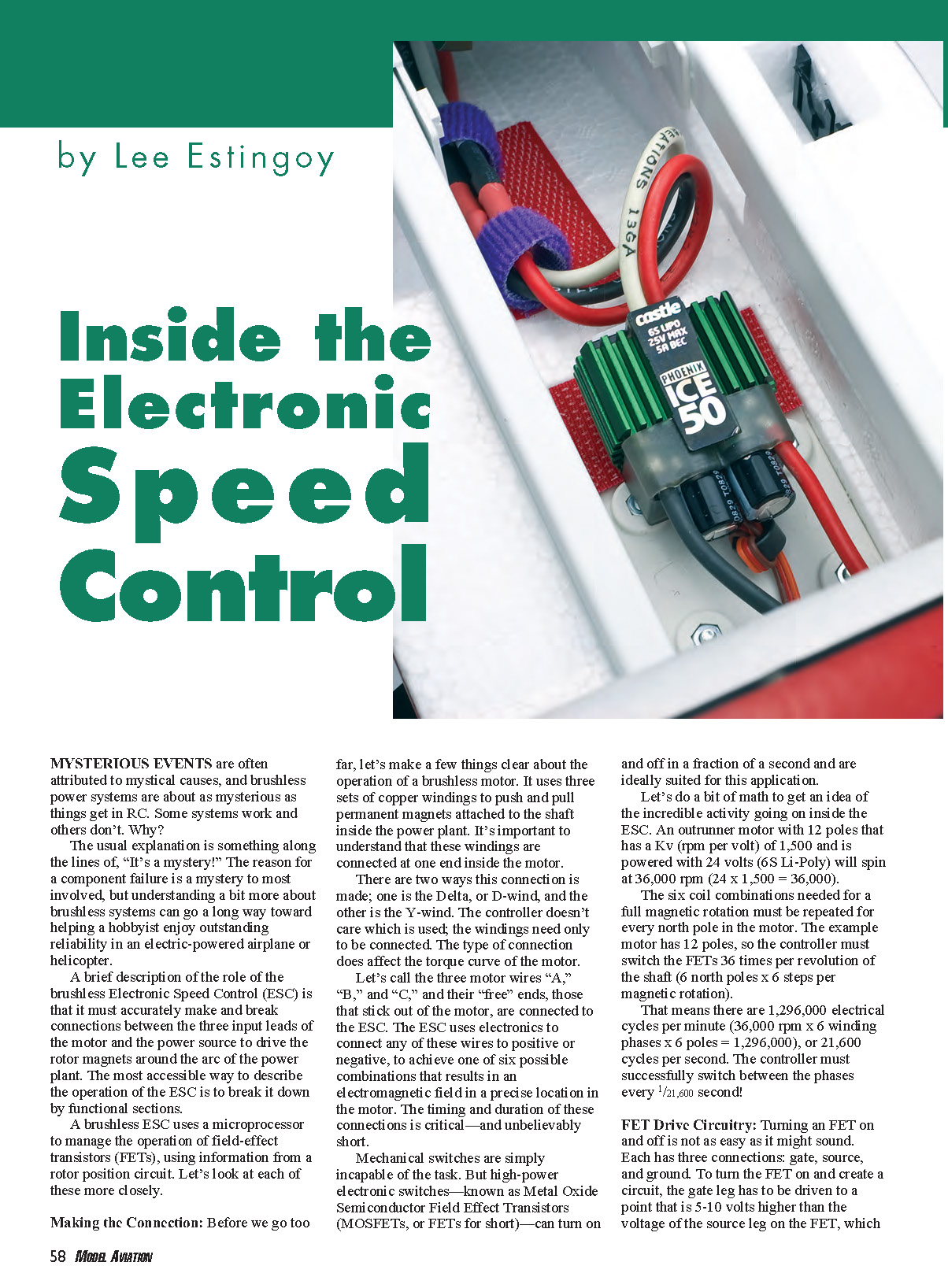
A brief description of the role of the brushless Electronic Speed Control (ESC) is that it must accurately make and break connections between the three input leads of the motor and the power source to drive the rotor magnets around the arc of the power plant. The most accessible way to describe the operation of the ESC is to break it down by functional sections.
A brushless ESC uses a microprocessor to manage the operation of field-effect transistors (FETs), using information from a rotor position circuit. Let's look at each of these more closely.
Making the Connection
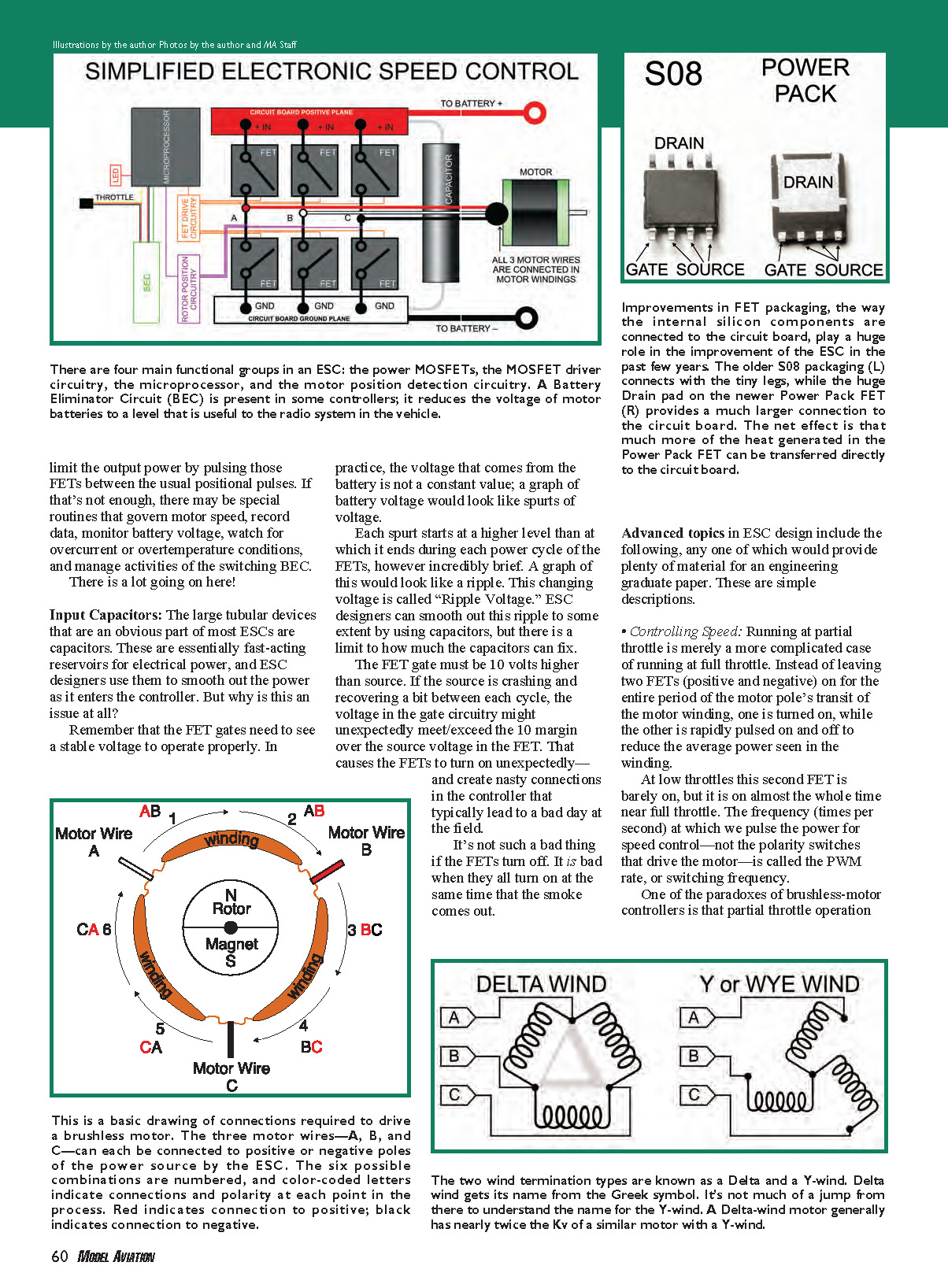
Before we go too far, let's make a few things clear about the operation of a brushless motor. It uses three sets of copper windings to push and pull permanent magnets attached to the shaft inside the power plant. It's important to understand that these windings are connected at one end inside the motor. There are two ways this connection is made: Delta (D-wind) and Y-wind. The controller doesn't care which is used; the windings need only be connected. The type of connection does affect the torque curve of the motor.
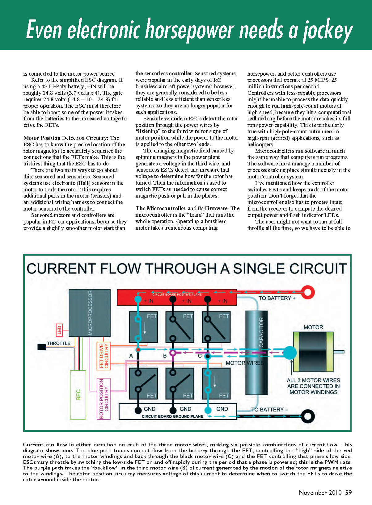
Let's call the three motor wires "A," "B," and "C." Their "free" ends, those that stick out of the motor, are connected to the ESC. The ESC uses electronics to connect any of these wires to positive or negative to achieve one of six possible combinations that results in an electromagnetic field in a precise location in the motor. The timing and duration of these connections is critical—and unbelievably short. Mechanical switches are simply incapable of the task. But high-power electronic switches—known as Metal Oxide Semiconductor Field Effect Transistors (MOSFETs, or FETs for short)—can turn on and off in a fraction of a second and are ideally suited for this application.
Consider the scale of activity inside the ESC. An outrunner motor with 12 poles and a Kv (rpm per volt) of 1,500 powered with 24 volts (6S Li-Poly) will spin at 36,000 rpm (24 × 1,500 = 36,000).
The six coil combinations needed for a full magnetic rotation must be repeated for every north pole in the motor. The example motor has 12 poles, so the controller must switch the FETs 36 times per revolution of the shaft (6 north poles × 6 steps per magnetic rotation). That means there are 1,296,000 electrical cycles per minute (36,000 rpm × 36 switching steps = 1,296,000), or 21,600 cycles per second. The controller must successfully switch between the phases every 1/21,600 second!
FET Drive Circuitry
Turning an FET on and off is not as easy as it might sound. Each FET has three connections: gate, source, and drain. To turn the FET on and create a circuit, the gate must be driven to a voltage typically 5–10 volts higher than the source. The source is connected to the motor power circuit, so the ESC must be able to generate that higher gate voltage from the battery supply.
For example, using a 4S Li-Poly battery gives roughly +IN = 14.8 volts (3.7 volts × 4). The gate might require about 24.8 volts (14.8 + 10 = 24.8) for proper operation in some configurations. The ESC therefore must boost some of the power it takes from the batteries to the increased voltage needed to drive the FETs.
Motor Position Detection Circuitry
The ESC has to know the precise location of the rotor magnet(s) to accurately sequence the FETs. This is the trickiest thing the ESC has to do.
There are two main approaches: sensored and sensorless. Sensored systems use electronic Hall sensors in the motor to track the rotor. This requires additional parts in the motor (sensors) and an additional wiring harness to connect the motor sensors to the controller. Sensored motors and controllers are popular in RC car applications because they provide a slightly smoother motor start than sensorless controllers. Sensored systems were popular in the early days of RC brushless aircraft power systems; however, they are generally considered to be less reliable and less efficient than sensorless systems and are no longer popular for most aircraft applications.
Sensorless/modern ESCs detect rotor position through the power wires by "listening" to the third wire for signs of motor position while power is applied to the other two leads. The changing magnetic field caused by spinning magnets induces a voltage in the third wire, and sensorless ESCs detect and measure that voltage to determine how far the rotor has turned. That information is then used to switch FETs as needed to produce the correct magnetic push or pull in the phases.
The Microcontroller and Its Firmware
The microcontroller is the "brain" that runs the whole operation. Operating a brushless motor takes significant computing horsepower, and better controllers use processors that operate at 25 MIPS (25 million instructions per second). Controllers with less-capable processors might be unable to process the data quickly enough to run high-pole-count motors at high speed, because they hit a computational limit long before the motor reaches its full rpm/power capability. This is particularly true with high-pole-count outrunners in high-rpm (geared) applications, such as helicopters.
Microcontrollers run firmware that must manage a number of processes simultaneously. In addition to switching FETs and tracking motor position, the microcontroller has to process input from the receiver to compute the desired output power, flash indicator LEDs, and manage speed control by pulsing FETs between positional pulses when partial throttle is requested.
Other routines may govern motor start behavior, record data, monitor battery voltage, watch for overcurrent or overtemperature conditions, and manage the switching BEC. There is a lot going on in the software.
Input Capacitors
The large tubular devices that are a visible part of most ESCs are capacitors. These are essentially fast-acting reservoirs for electrical power, used to smooth out the power as it enters the controller. Why is this necessary?
FET gates need to see a stable voltage to operate properly. In practice, battery voltage is not perfectly steady; during switching it shows rapid variations that look like ripple. Each switching event causes the source voltage to dip and recover briefly. This ripple voltage can cause the gate-to-source margin to fluctuate.
If the gate is momentarily driven to a voltage that meets or exceeds the required margin over the (dipping) source, FETs can turn on unexpectedly and create unwanted connections in the controller. It's not catastrophic if a single FET turns off, but it's disastrous when multiple FETs turn on at once—the result can be immediate failure.
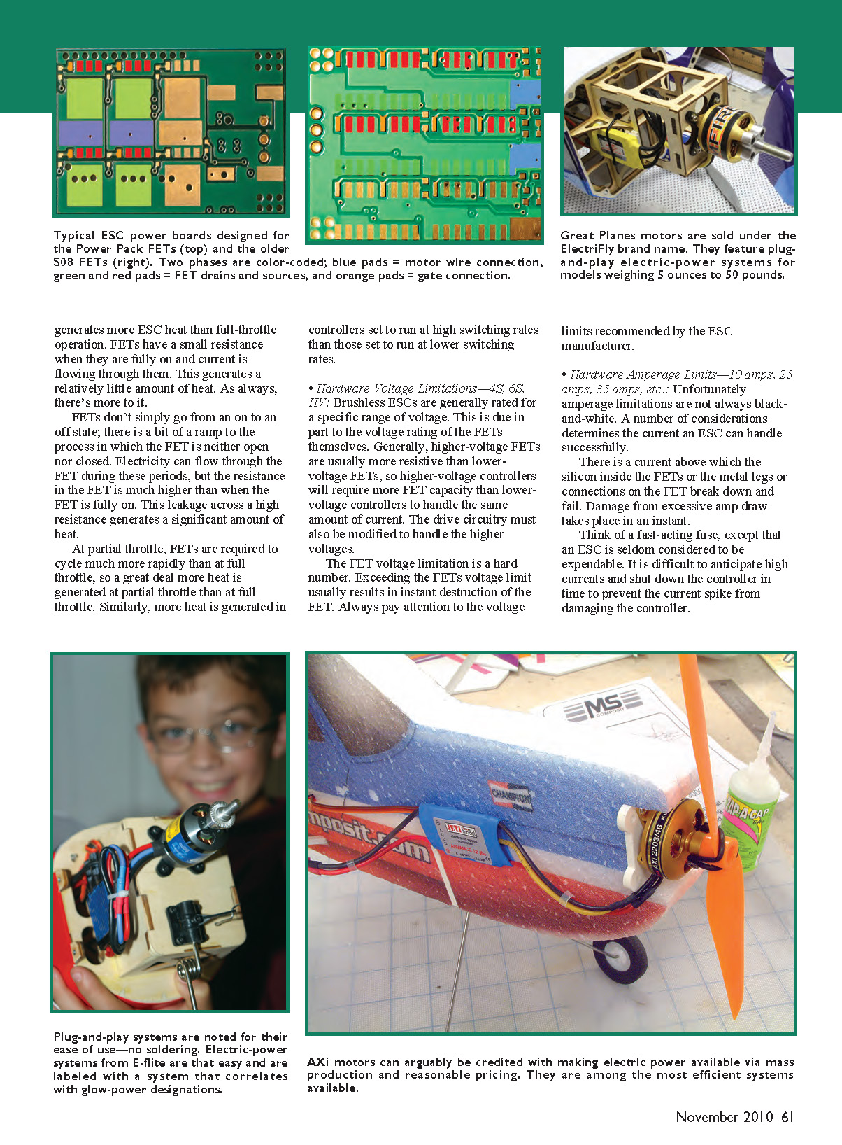
Capacitors help smooth the ripple, but there is a limit to how much they can fix. Improvements in FET packaging and board layout have also significantly improved ESC reliability. Newer Power Pack FETs have much larger drain pads and better thermal connections to the circuit board than older small-leg packages, allowing more heat generated in the FET to be transferred to the PCB.
Advanced topics in ESC design
The following are brief descriptions of advanced topics; each could be an engineering paper on its own.
- Controlling Speed:
- Running at partial throttle is a more complicated case of running at full throttle. Instead of leaving two FETs (positive and negative) on for the entire period of a motor pole's transit, one is turned on while the other is rapidly pulsed on and off to reduce the average power seen in the winding.
- At low throttle the pulsed FET is on only briefly; near full throttle it is on for most of the period. The frequency at which this pulsing occurs (the PWM rate or switching frequency) determines how the motor sees the average power.
- One paradox is that partial-throttle operation often generates more ESC heat than full-throttle operation. FETs have small resistance when fully on, so fully on operation produces relatively little heat. But FETs do not switch instantaneously—during transitions their resistance is higher, and significant heat can be generated. Because partial throttle requires much more rapid switching for PWM control, more heat is produced at partial throttle than at full throttle. Higher PWM rates also increase heat.
- Hardware Voltage Limitations — 4S, 6S, HV:
- ESCs are generally rated for a specific voltage range, partly due to the voltage rating of the FETs. Higher-voltage FETs are often more resistive than lower-voltage FETs, so higher-voltage controllers may require more FET capacity to handle the same current.
- Drive circuitry must also be designed to handle higher voltages. Exceeding the FET voltage limit typically results in instant destruction of the FETs. Always observe the voltage limits recommended by the ESC manufacturer.
- Hardware Amperage Limits — 10 A, 25 A, 35 A, etc.:
- Amperage limits are not always black-and-white. Excessive current can cause instantaneous damage to the silicon inside FETs or to their metal legs and board connections.
- Partial-throttle operation and high PWM rates generate more heat; an ESC's current capability is limited by its ability to dissipate that heat. If a controller makes more heat than it can dissipate, a runaway thermal condition can occur, leading to thermal destruction: solder melts and components become loose.
- A useful rating is "steady state amperage" — the maximum current an ESC can carry at its rated voltage without further temperature rise. This depends on ambient temperature and airflow over the ESC.
- "Surge" or "burst" ratings are sometimes cited, but these may be defined inconsistently and can be shorter than expected. Read the fine print.
Like the proverbial duck on water, things look calm on top but there’s a whole lot going on inside a brushless motor controller. A great deal of engineering goes into the physical design, and the firmware is surprisingly complex. Always use a power system inside its performance envelope for best performance and reliability.
Lee Estingoy [email protected]
Sources
- Himax motors: Maxx Products International — (800) 416-6299 — www.maxxprod.com
- E-flite — (800) 338-4639 — www.e-flite.com
- ElectriFly — (800) 637-7660 — www.electrifly.com
- AXi electronics: Hobby Lobby — (866) 512-1444 — www.hobby-lobby.com
- Castle Creations — (913) 390-6939 — www.castlecreations.com
Transcribed from original scans by AI. Minor OCR errors may remain.

