
INSTRUCTOR'S HELPER
The Buddy Box 2 can help newcomers to get a "feel" for stick movements
Steven Hunt
I soloed September 27, 1987, and have been instructing fixed-wing for roughly seven years and basic helicopter for approximately two years.
My club is Casper Airmodelers, which has several qualified instructors and a club-owned and -maintained trainer with buddy box. One night a week during the summer flying season is set aside as Trainer Night from 5 p.m. to dusk, giving any students with trainers the available instructors of the evening and priority airtime.
This time is also used for any persons who would like to "try before they buy" using the club trainer and its designated instructor. New club members are able to set up appointments during other times with instructors who can instruct during the day.
Casper Airmodelers' solo rate is very good, and most who come to instruction more than twice a month have learned to fly.
As instructors, we have almost become dependent on the buddy box, and cringe when a new student brings an airplane with a radio that cannot be linked to a buddy box.
We have pretty much agreed on the biggest problems: overcorrecting, inability to see the airplane, undercorrection, insufficient attention span, and overcorrecting.
The vision problem is usually simple; new glasses tend to help, or just learning the attitude of the airplane. The attention span usually improves.
The correction problems are something that has to be learned, and for some it takes longer. I have found that having two sets of thumbs on the transmitter is difficult, and usually results in little gain.
But what if a student could watch the airplane and see what the inputs are at the same time? How about feeling the same stick movements the instructor is giving while watching the airplane?
By removing the guts of a transmitter and installing a receiver and servos, the box can respond with the same movements the instructor is giving to the airplane. The student can then watch the airplane while he or she feels how much input to give, and when to do what.
Most of the students I have introduced to this instruction seem to have spent far less time learning over- and undercorrection. It can be used to show the first-time fliers the basics; the more-advanced students where, when, and how much to flare for landing; advanced can learn how to get into and out of a flat spin, and so on.
I have made two of these boxes. The first was with a Futaba 1024 body; this was very difficult to connect to the gimbals and was extremely short on room for the servos. Should you be considering building one of these, I highly recommend locating one of the older, squared-off "can" transmitters with open gimbals; there is plenty of room, there are flat surfaces for mounting, and the open gimbals are fairly easy to convert.
Most of the parts I used were items that still worked but had broken mounting ears, or I just did not feel that I could trust in an airplane. When completed, this project will not cause interference or cause a problem to the related airplane if it fails in use.
Preparation
The first step is to gather all of the stuff needed and test the receiver and servos to be sure they work with the transmitter of the airplane you are going to use. Most clubs have a transmitter like this laying in a basement. Almost everyone who has crashed has a sender he or she doesn't trust in an airplane.
Fly the airplane that is to be used with this box, and be sure it is in trim. Put masking tape on the transmitter next to the trim levers and mark each trim so you have it later after you knock the trims out on the way home. Read and understand the rest of this article before you continue.
Remove the back from the transmitter to be converted. Do not remove the back from the aircraft transmitter—no changes necessary.
Remove everything from inside the can except the gimbals and their four pots, the meter, and one switch. If the antenna is attached to the can, it can be used as the receiver antenna, but if it is connected directly to the circuit boards as the newer radios are, it must be removed and the receiver antenna just left out the top of the can. The switch can be almost any switch that will fit and will not be in the way of the servos or pushrods. I used a retract switch above one of the gimbals. Do not damage the meter or its terminals unless you do not want to use the meter as an on indicator. You would not need the resistor if you don't want the meter.
Making the gimbal rods
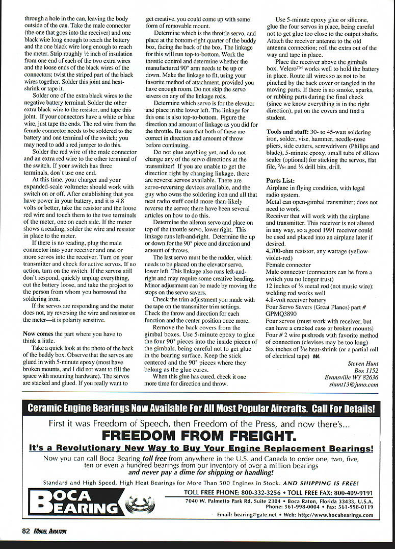
- Flatten 5/8 inch of a 1/8-inch rod to 1/16 inch thick, using a hammer and a hard flat surface; most vises have small anvils built onto them.
- Round off the end with a file and drill a 1/64-inch hole roughly 1/8 inch from the end in this flat area.
- Place this flattened end into the vise jaws 3/8 inch and bend to 90°.
- Cut off at one inch.
You should now have a 1/8-inch piece of wire bent 90° with one leg one inch long and the other leg 3/4 inch long, flattened with a hole in the flat spot. (With both legs laying on a horizontal surface, the flattened area has to be vertical.)
Make a total of four of these rods. The dimensions are not critical, but you should have a little rod left in case you need to make another. Use coarse sandpaper on the cut end for approximately 1/2 inch.
Take one of the gimbal boxes apart and discard any centering springs; keep the trim levers. Remove the backs of the pots and remove the half shaft, but leave the shaft guide of the pot. Drill the guide hole to 1/8 inch so the rods you made in the last step will fit through the guide hole without binding.
Assemble the gimbal using the 1/8-inch rods in place of the pot shafts; the shafts may be loose at this time. Convert the other gimbal in the same manner. The sticks should move with very little effort at this point.
Electrical conversion
- Take the female connector (the one you plug your charger into) and route its wires through a hole in the can, leaving the connector body outside of the can.
- Take the male connector (the one that goes into the receiver) and prepare one black wire long enough to reach the battery and another black wire long enough to reach the meter. Strip roughly 1/8 inch of insulation from one end of each of the two extra wires and the loose ends of the black wires or the connectors; twist the stripped parts of the black wires together. Solder this joint and heat-shrink or tape it.
- Solder one end of the extra black wires to the negative battery terminal. Solder the other extra black wire to the resistor, and tape this joint. If your connectors have a white or blue wire, just tape the ends.
- The red wire from the female connector needs to be soldered to the battery and one terminal of the switch; you may need to add a red jumper to do this.
- Solder the red wire of the male connector and an extra red wire to the other terminal of the switch. If your switch has three terminals, don't use one end.
At this time, turn on your charger and your expanded-scale voltmeter should work with the switch on or off. After establishing that you have power in your battery, and it is 4.8 volts or better, take the resistor and the loose red wire and touch them to the two terminals of the meter, one on each side. If the meter shows a reading, solder the wire and resistor in place to the meter.
If there is no reading, plug the male connector into your receiver and one or more servos into the receiver. Turn on your transmitter and check for active servos. If no action, turn on the switch. If the servos still don't respond, quickly unplug everything, disconnect the battery, and take the project to the person from whom you borrowed the soldering iron.
If the servos are responding and the meter does not, try reversing the wire and resistor on the meter—it is polarity sensitive.
Servo placement and linkage
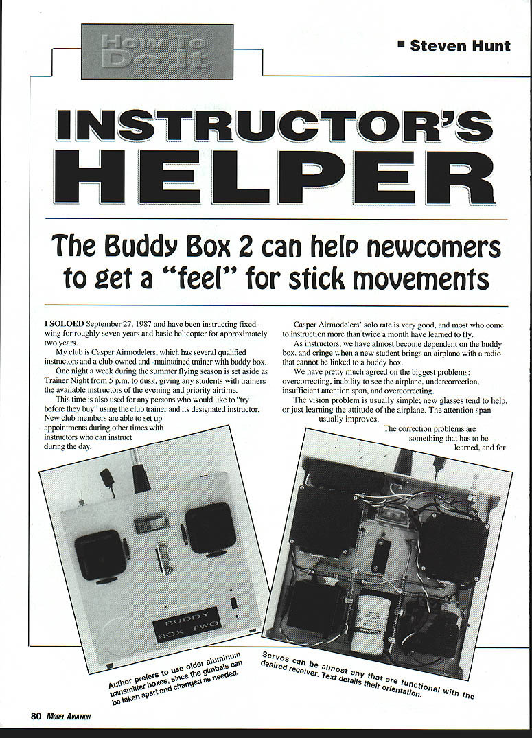
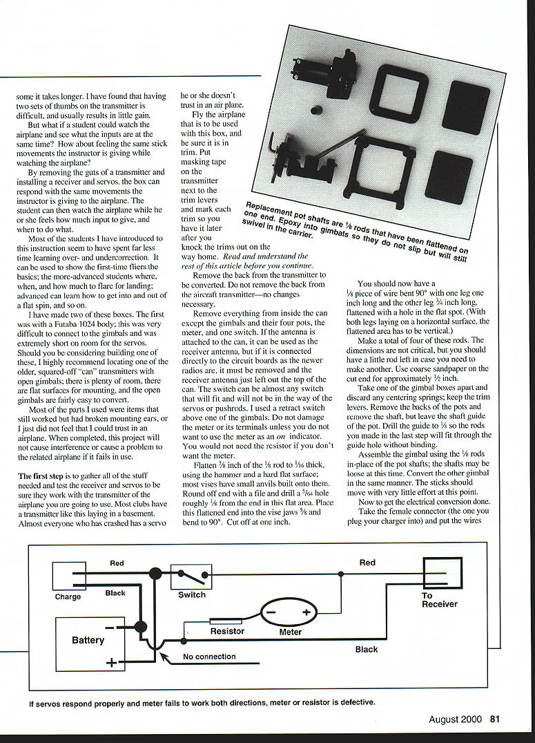
Take a quick look at the photo of the back of the buddy box. Observe that the servos are glued in with 5-minute epoxy (most have broken mounts, and I did not want to fill the space with mounting hardware). The servos are stacked and glued. If you really want to get creative, you could come up with some form of removable mount.
- Determine which is the throttle servo, and place it in the thumb-right quarter of the buddy box, facing the back of the box. The linkage for this will run top-to-bottom. Work the throttle control and determine whether the manufactured 90° arm needs to be up or down. Make the linkage to fit, using your favorite method of attachment, provided you have enough room. Do not skip the servo savers on any of the linkage rods.
- Determine which servo is for the elevator and place it in the lower left. The linkage for this one is also top-to-bottom. Figure the direction and amount of linkage as you did for the throttle. Be sure that both of these are correct in direction and amount of throw before continuing.
- Do not glue anything yet, and do not change any of the servo directions at the transmitter! If you are unable to get the direction right by changing linkage, there are reverse servos available. There are servo-reversing devices available, and the guy who owns the soldering iron and all that neat radio stuff could more-than-likely reverse the servo; there have been several articles on how to do this.
- Determine the aileron servo and place it on top of the throttle servo, lower right. This linkage runs left-and-right. Determine the up or down for the 90° piece and direction and amount of throw.
- The last servo must be the rudder, which needs to be placed on the elevator servo, lower left. This linkage also runs left-and-right and may require some creative bending. Minor adjustments can be made by moving the stops on the servo savers.
Check the trim adjustment you made with the trim springs on the transmitter trim settings. Check the throw and direction for each function and the center position of each servo.
Remove the back covers from the gimbal boxes. Use 5-minute epoxy to glue the four 90° pieces into the inside pieces of the gimbals, being careful not to get glue in the bearing surfaces. Keep the stick centered and the 90° pieces where they belong as the glue cures.
When this glue has cured, check it one more time for direction and throw.
Use 5-minute epoxy glue or silicone to glue the four servos in place, being careful not to get glue too close to the output shafts. Attach the receiver antenna to the old antenna connection; roll the extra out of the way and tape in place.
Place the receiver above the gimbal box. Velcro™ works well to hold the battery in place. Route all wires so as not to be pinched by the back cover or tangled in the moving parts. If there is no smoke, sparks, or rubbing parts during the final check (since we know everything is in the right direction), put on the covers and find a student.
Troubleshooting
- If servos respond properly and the meter fails to work both directions, the meter or resistor is defective.
- If servos do not respond, unplug everything immediately and recheck wiring and power.
- If the meter does not read but servos do, reverse the meter wiring (it is polarity sensitive).
Tools and stuff
- 30- to 45-watt soldering iron
- Solder
- Vise
- Hammer
- Needle-nose pliers
- Side cutters
- Screwdrivers (Phillips and blade)
- 5-minute epoxy
- Small tube of silicone sealer (optional) for sticking the servos
- Flat file
- 5/64" and 1/8" drill bits
- Drill
Parts List
- Airplane in flying condition, with legal radio system.
- Metal can open-gimbal transmitter; does not need to work.
- Receiver that will work with the airplane and transmitter. This receiver is not altered in any way, so a good 1991 receiver could be used and placed into an airplane later if desired.
- 4,700-ohm resistor, any wattage (yellow-violet-red)
- Female connector
- Male connector (connectors can be from a switch you no longer trust)
- 12 inches of 3/16" metal rod (not music wire); welding rod works well
- 4–8 volt receiver battery
- Four Servo Savers (Great Planes) part # GPMQ3890
- Four servo horns (must work with receiver, but can have a cracked case or broken mounts)
- Four #2 wire pushrods with favorite method of connection (clevises may be too long)
- Six inches of 3/16" heat-shrink (or a partial roll of electrical tape)
MA
Steve Hunt Box 1152 Evansville WY 82636 [email protected]
Transcribed from original scans by AI. Minor OCR errors may remain.

