
J2M Raiden
by John Glezellis
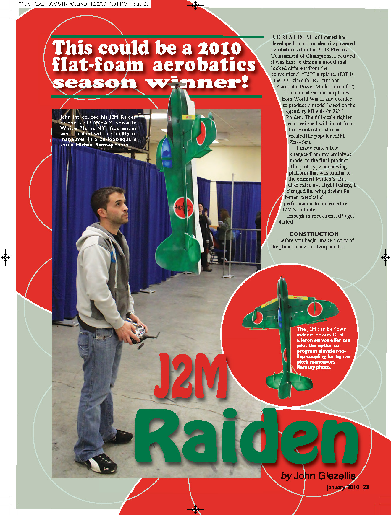
A great deal of interest has developed in indoor electric-powered aerobatics. After the 2008 Electric Tournament of Champions, I decided it was time to design a model that looked different from the conventional "F3P" airplane. (F3P is the FAI class for RC "Indoor Aerobatic Power Model Aircraft.") I looked at various airplanes from World War II and decided to produce a model based on the legendary Mitsubishi J2M Raiden. The full-scale fighter was designed with input from Jiro Horikoshi, who had created the popular A6M Zero-Sen.
I made quite a few changes from my prototype model to the final product. The prototype had a wing platform that was similar to the original Raiden's. But after extensive flight-testing, I changed the wing design for better aerobatic performance, to increase the J2M's roll rate.
Enough introduction; let's get started.
CONSTRUCTION
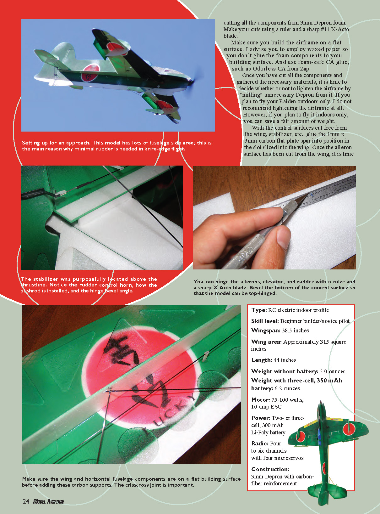
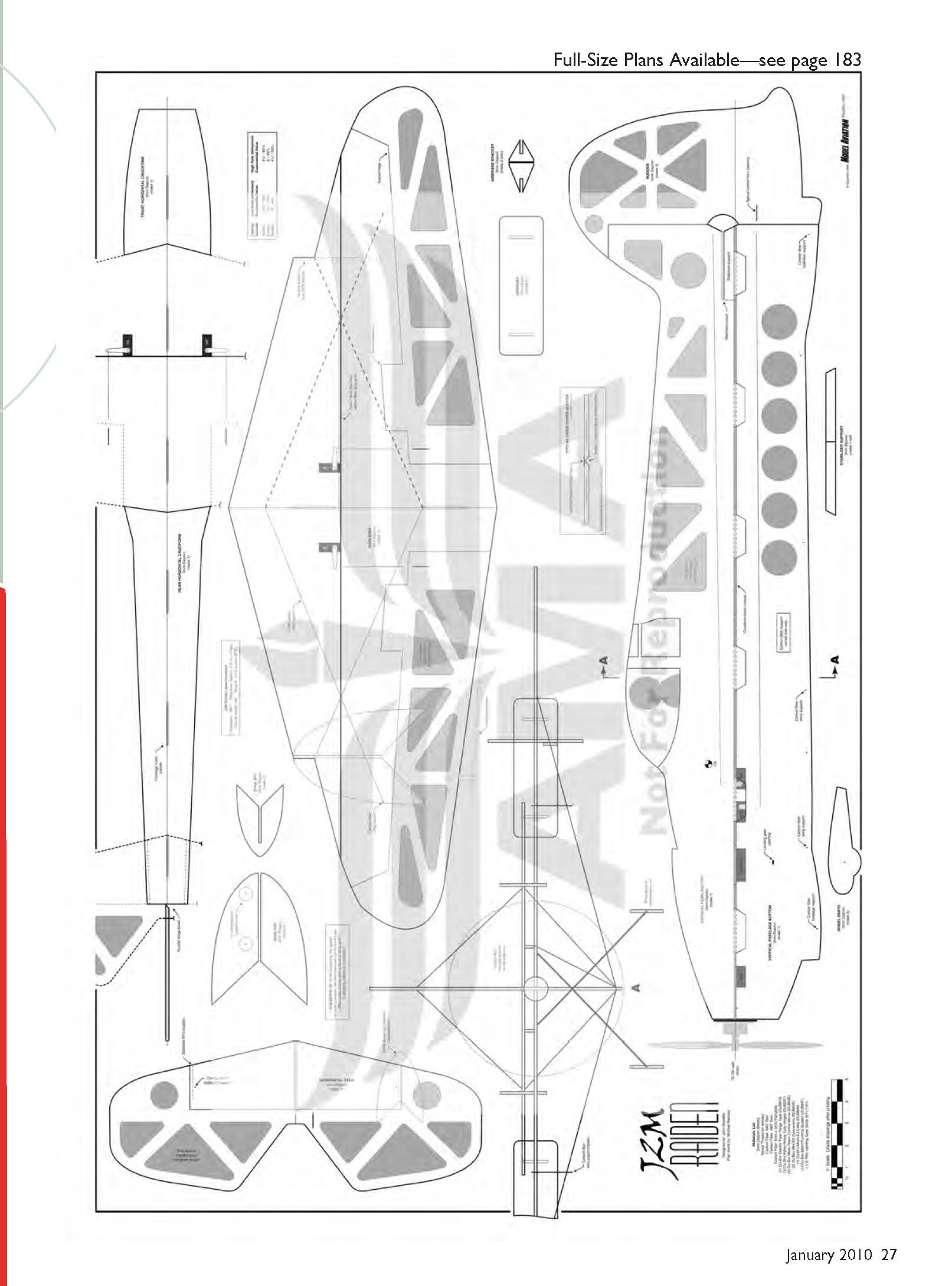
Before you begin, make a copy of the plans to use as a template for cutting all the components from 3mm Depron foam. Make your cuts using a ruler and a sharp #11 X-Acto blade.
Make sure you build the airframe on a flat surface. I advise you to employ waxed paper so you don't glue the foam components to your building surface. Use foam-safe CA glue, such as Odorless CA from Zap.
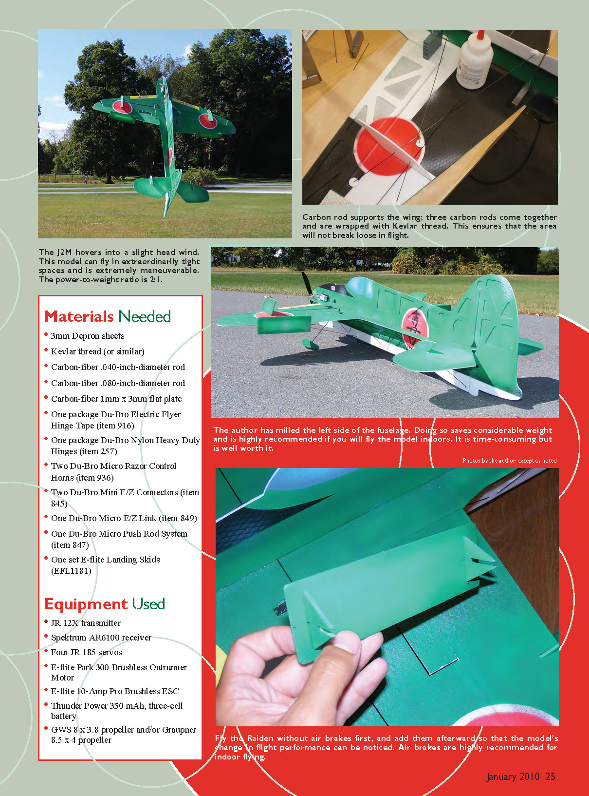
Once you have cut all the components and gathered the necessary materials, decide whether or not to lighten the airframe by "milling" unnecessary Depron from it. If you plan to fly your Raiden outdoors only, I do not recommend lightening the airframe. If you plan to fly it indoors only, you can save a fair amount of weight by removing excess foam.
With the control surfaces cut free from the wing, stabilizer, etc., glue the 1mm x 3mm carbon flat-plate spar into position in the slot sliced into the wing.
Hinging control surfaces
I top-hinge my aerobatic foam models that are built from 3mm Depron. To top-hinge:
- Bevel the bottom of the control surface (aileron, elevator, rudder) either by sanding the bottom of the leading edge of the surface or by using a ruler and a sharp #11 X-Acto blade.
- When satisfied with the bevel, place the control surface in position and apply hinge tape over the control surface.
- Follow the same steps for the elevator and rudder.
Make sure the wing and horizontal fuselage components are on a flat building surface before adding carbon supports. The crisscross joint is important.
Assembly steps
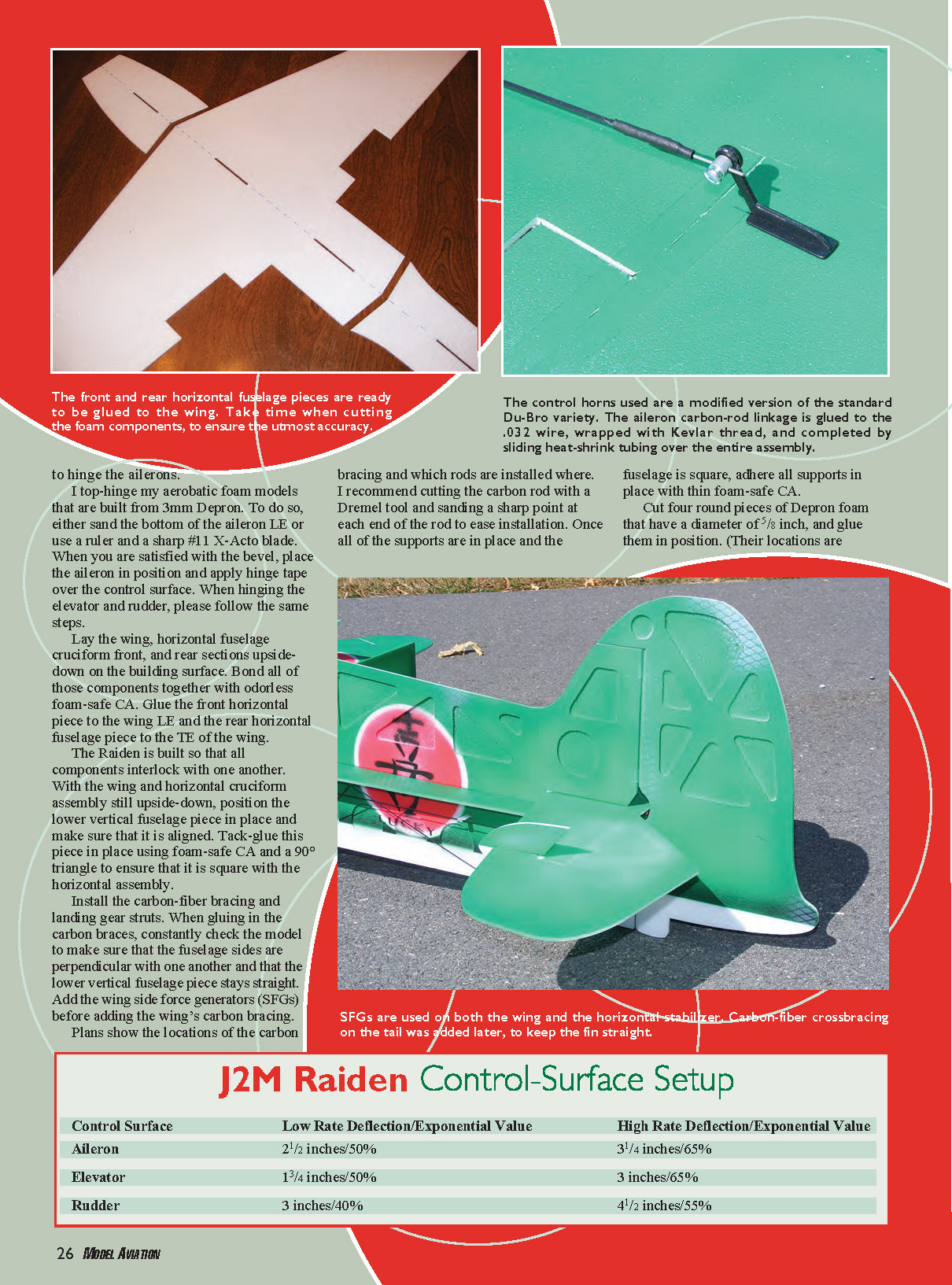
- Lay the wing, horizontal fuselage cruciform front, and rear sections upside-down on the building surface. Bond all of those components together with odorless foam-safe CA.
- Glue the front horizontal piece to the wing leading edge (LE) and the rear horizontal fuselage piece to the trailing edge (TE) of the wing.
- The Raiden is built so that all components interlock with one another. With the wing and horizontal cruciform assembly still upside-down, position the lower vertical fuselage piece in place and make sure that it is aligned. Tack-glue this piece in place using foam-safe CA and a 90° triangle to ensure that it is square with the horizontal assembly.
- Install the carbon-fiber bracing and landing gear struts. When gluing in the carbon braces, constantly check the model to make sure that the fuselage sides are perpendicular with one another and that the lower vertical fuselage piece stays straight.
- Add the wing side force generators (SFGs) before adding the wing’s carbon bracing. The plans show the locations of the carbon bracing and which rods are installed where.
- I recommend cutting the carbon rod with a Dremel tool and sanding a sharp point at each end of the rod to ease installation.
- Once all of the supports are in place and the fuselage is square, adhere all supports in place with thin foam-safe CA.
Cut four round pieces of Depron foam with a diameter of 5/8 inch, and glue them in position. Their locations are shown on the plans.
Tools and materials notes
- Use a ruler and a sharp #11 X-Acto blade for precise cutting and beveling.
- Use waxed paper on your building surface to prevent accidental gluing.
- Use foam-safe, odorless CA glue for bonding Depron foam and carbon components.
- Use a Dremel tool to cut carbon fiber rods and sand points on the ends for easier installation.
Specifications
- Type: RC electric indoor profile
- Skill level: Beginner builder / novice pilot
- Wingspan: 38.5 inches
- Wing area: Approximately 315 square inches
- Length: 44 inches
- Weight without battery: 5.0 ounces
- Weight with three-cell, 350 mAh battery: 6.2 ounces
- Motor: 75–100 watts, 10-amp ESC
- Power: Two- or three-cell, 300–350 mAh Li-Poly battery
- Radio: Four to six channels with four microservos
- Construction: 3mm Depron with carbon-fiber reinforcement
J2M Raiden Control-Surface Setup
Control Surface — Low Rate Deflection / Exponential Value — High Rate Deflection / Exponential Value
- Aileron: 2 1/2 inches / 50% — 3 1/4 inches / 65%
- Elevator: 1 3/4 inches / 50% — 3 inches / 65%
- Rudder: 3 inches / 40% — 4 1/2 inches / 55%
No primary article text appears on this scanned page — it contains only the full-size plans/diagram for the J2M Raiden.
Transcribed from original scans by AI. Minor OCR errors may remain.

